
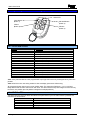
EN50131-1
Security Grade 2
Environmental Class 2
RINS915-2
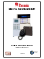
ICON & LCD User Manual
Software Version 5
Matrix 424/832/832+


Matrix User Guide
RINS915-2 Page i
CONTENTS
CHAPTER 1: INTRODUCTION............................................................................................... 1
CHAPTER 2: REPLACING THE BATTERIES........................................................................ 2
CHAPTER 3: DISPLAYS ........................................................................................................ 3
3.1 LAYOUT & KEY OPERATION ............................................................................................................3
3.2 ICON SYMBOL MEANINGS................................................................................................................4
3.3 LCD SYMBOL MEANINGS................................................................................................................5
3.4 PROXIMITY READER LED MEANINGS ...............................................................................................5
3.5 KEY FOB SYMBOLS AND MEANINGS (KF4DW).................................................................................6
3.5.1 The KF4DW Actions ...............................................................................................................6
3.5.2 STATUS LEDS .......................................................................................................................6
3.6 HIDDEN DISPLAY MODE ..................................................................................................................7
3.7 LATCHING ALARMS – DENMARK, NORWAY, FINLAND & SWEDEN ONLY ............................................7
3.8 ARM MODES – SINGLE PARTITION...................................................................................................8
3.9 PARTITION INDICATIONS..................................................................................................................9
3.9.1 LCD Keypad – Multiple Partitions ...........................................................................................9
3.9.2 Icon Keypad..........................................................................................................................10
3.10 DISPLAYING SYSTEM FAULTS......................................................................................................12
3.10.1 Icon Keypad........................................................................................................................12
3.10.2 LCD Keypad .......................................................................................................................12
3.11 DISPLAYING OPEN ZONES...........................................................................................................13
3.12 LATCHING SYSTEM FAULTS – NORWAY, DENMARK, FINLAND & SWEDEN .....................................13
3.13 LATCHING BATTERY FAULT.........................................................................................................13
3.14 ANTI-CODE / ENGINEER RESET....................................................................................................13
CHAPTER 4: ARMING / DISARMING THE SYSTEM .......................................................... 14
4.1 ICON KEYPAD ...............................................................................................................................14
4.1.1 Arming – Single Partition User..............................................................................................14
4.1.2 Displaying the Armed Status ................................................................................................14
4.1.3 Disarming the System – Single Partition User......................................................................14
4.1.4 Latched Alarm Condition – Denmark, Finland, Norway & Sweden Only ..............................15
4.1.5 Anti-Code Reset ...................................................................................................................15
4.1.6 Arming – Multiple Partition User ...........................................................................................16
4.1.7 Displaying the Armed Status – Multiple Partition User .........................................................16
4.1.8 Disarming the System – Multiple Partition User....................................................................16
4.1.9 Latched Alarm Condition – Denmark, Finland, Norway & Sweden Only – Multiple Partition17
4.1.10 Anti-Code Reset – Multiple Partition User ..........................................................................17
4.2 LCD KEYPAD ...............................................................................................................................18
4.2.1 Arming – Single Partition User..............................................................................................18
4.2.2 Displaying the Armed Status – Single Partition User............................................................18
4.2.3 Disarming – Single Partition User.........................................................................................18
4.2.4 Latched Alarm Indication – Denmark, Norway, Finland & Sweden only – Single Partition...19
4.2.5 Anti-Code Reset – Single Partition User...............................................................................19
4.2.6 Arming – Multiple Partition User ...........................................................................................19
4.2.7 Displaying the Armed Status – Multiple Partition User .........................................................20
4.2.8 Disarming – Multiple Partition User ......................................................................................20
4.2.9 Latched Alarm Indication – Denmark, Norway, Finland & Sweden only – Multiple Partition 21
4.2.10 Anti-Code Reset – Multiple Partition User ..........................................................................21
4.3 PARTITIONS ..................................................................................................................................22
4.3.1 Part Sets Explained ..............................................................................................................22
4.3.2 Partitions Explained ..............................................................................................................22
4.3.3 Partition Dependency ...........................................................................................................22
4.4 DURESS ARMING / DISARMING ......................................................................................................23
4.4.1 Entering a Duress Code .......................................................................................................23

Matrix User Guide
Page ii RINS915-2
4.5 FAULT TONES...............................................................................................................................23
4.6 EMERGENCY SERVICES.................................................................................................................23
4.6.1 Activating a Fire Alarm..........................................................................................................23
4.6.2 Activating a Personal Attack (P.A) Alarm .............................................................................23
4.6.3 Activating a Medical Alarm ...................................................................................................23
CHAPTER 5: USER FUNCTIONS........................................................................................ 24
5.1 AVAILABLE USER FUNCTIONS .......................................................................................................24
5.2 ENTERING USER MODE.................................................................................................................25
5.3 EXITING USER MODE ....................................................................................................................25
5.4 ARM WITH OMITS ..........................................................................................................................26
5.5 DISPLAY LOG ...............................................................................................................................27
5.6 SET VOLUME ................................................................................................................................28
5.7 SET BACKLIGHT ...........................................................................................................................29
5.8 VIEW TIME AND DATE ...................................................................................................................30
5.9 CHANGE TIME...............................................................................................................................31
5.10 CHANGE DATE............................................................................................................................32
5.11 CHANGING/DELETING USER CODES AND ATTRIBUTES – ICON KEYPAD ........................................33
5.11.1 Changing/Deleting a Code..................................................................................................33
5.11.2 Add/Delete/Change Users ..................................................................................................33
5.12 CHANGING USER CODES AND ATTRIBUTES – LCD KEYPAD.........................................................35
5.12.1 Changing a User Code .......................................................................................................35
5.12.2 Editing User Codes and Attributes......................................................................................36
5.13 EDITING USER NAME – LCD KEYPAD ONLY ................................................................................39
5.14 ADJUSTING THE PROXIMITY VOLUME...........................................................................................41
5.15 ADDING/REMOVING PROXIMITY CARDS & TAGS...........................................................................42
5.16 ADDING / REMOVING KEY FOBS...................................................................................................43
5.17 PERFORMING AN NVM RESET ON A KEYFOB................................................................................44
5.18 SYSTEM TEST .............................................................................................................................45
5.19 ACTIVATING PGM FROM THE KEYPAD .........................................................................................45
5.20 UPLOAD/DOWNLOAD 1 HOUR WINDOW .......................................................................................46
5.21 ZONE TYPE DESCRIPTIONS .........................................................................................................47
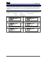
CHAPTER 6: ZONE & PARTITION INDICATION TABLE ................................................... 48
CHAPTER 7: PROXIMITY READER.................................................................................... 49
7.1 INTRODUCTION.........................................................................................................................49
7.2 SINGLE PARTITION OPERATION.....................................................................................................49
7.2.1 Arming the Panel ..................................................................................................................49
7.2.2 Disarming the Panel .............................................................................................................50
7.3 MULTI-PARTITION OPERATION ......................................................................................................50
7.3.1 Arming the Panel ..................................................................................................................50
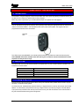
CHAPTER 8: THE KEYFOB................................................................................................. 51
8.1 INTRODUCTION .............................................................................................................................51
8.2 HOW TO USE THE KEYFOB .............................................................................................................51
8.3 STATUS LED ................................................................................................................................51
8.4 LOCKING A KEY FOB ....................................................................................................................51
CHAPTER 9: EVENT LOG TABLES.................................................................................... 52
9.1 ICON KEYPAD LOG TABLE ............................................................................................................52
9.2 LCD KEYPAD LOG TABLE.............................................................................................................54
9.3 VIEWING LOG AFTER A ZONE ALARM.............................................................................................56

Matrix User Guide
RINS915-2 Page 1
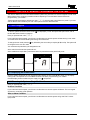
CHAPTER 1: INTRODUCTION
Thank you for buying the Matrix control panel, which uses the latest technology in design and manufacture. As
the end user of the Matrix security system, this manual has been written to help you use the many functions
available enabling you to get the best out of the Matrix alarm panel. Once you are familiar with the panel and its
functions, it is advisable to change the default Master User code.
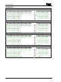
The system can be operated in the following modes from which different options are available to the end user:
Master and Limited User Functions
Master Limited User Function Description
9 9
Arm with Omits Allows zones to be omitted whilst arming the panel
9 9
Display Log Allows you to view the event log
9 9
Set Volume Allows you to alter the volume setting for your keypad
9 9
Set Backlight Allows you to set the backlight intensity
9 9
View Time & Date Allows you to view the panel’s time and date settings
9 8
Change Time
Allows you to change the alarm panel time
9 8
Change Date
Allows you to change the alarm panel date
9 8
Edit User
Allows you to edit user types/attributes
9 8
Change Codes
Allows you to change a users code only
9 8
Edit User Name
Allows you to edit user names
9 8
Proximity Volume
Allows you to change the volume of a proximity reader
9 8
Proximity Cards
Allows you to add/delete proximity cards
9 8
Add keyfob
Allows you to add/delete key fobs
9 8
Pulse PGM 1
Allows you to activate a PGM output
9 8
1 Hr Active
Allows you to open a 1hour up/download time window
9 8
System Test
Allows you to perform a minimal keypad/panel test
NOTE: There are no user serviceable parts inside.
Quick Start
To Arm / Disarm via ICON go to page 14
To Arm / Disarm via LCD go to page 18
To Arm / Disarm via Prox go to page 49
To Arm / Disarm via keyfob go to page 51

Matrix User Guide
Page 2 RINS915-2
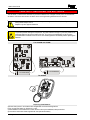
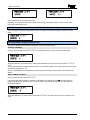
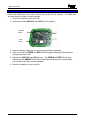
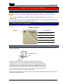
CHAPTER 2: REPLACING THE BATTERIES
The KX12DW, UT3DW and KF4DW will require there batteries to be changed at some point. As the batteries
are lithium ones extra care needs to be taken when removing/inserting batteries into the devices.
The batteries supplied have been chosen to provide long service life whilst, for safety reasons,
having limited output current.
Replace only with approved batteries.
To prevent possible damage to components, any static electrical charge on your body needs to be
eliminated before touching the inside of the unit. This can be accomplished by touching some
grounded/earthed metallic conductor such as a radiator/pipework immediately before replacing the
batteries.
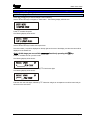
The KX12DW and UT3DW
3.6 AA LITHIUM BATTERY
8
A
l
a
r
m
9
+
-
9
8
3.6 AA LITHIUM BATTERY
+
-
The KF4DW
CAUTION
Disposing Used Batteries
a) Ensure that you act in accordance with all applicable environmental regulations.
b) Do not open the battery or dispose of in a fire.
c) Small batteries can be attractive to small children and may be swallowed; take precautions.
d) Consult the information sheet supplied with the replacement battery

Matrix User Guide
RINS915-2 Page: 3
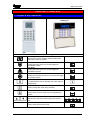
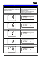
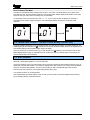
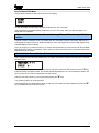
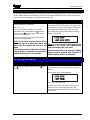
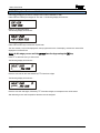
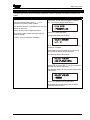
CHAPTER 3: DISPLAYS
3.1 Layout & Key Operation
Icon Keypad
LCD Keypad
Button Meanings
LL
Seven Segment Display
Shows zone numbers, partitions armed, system faults,
and event memory log number.
Personal Attack Alarm
Holding this button down for 2 seconds triggers an
immediate PA alarm.
Fire Alarm
Holding this button down for 2 seconds triggers an
immediate Fire alarm.
Medical button
Holding the medical button down for 2 seconds will trigger
an emergency alarm.
Numerical buttons
Functional buttons used for imputing user codes and user
programming.
Arm button
Used to change arm mode during exit delay
C
Function button
Used to enter / exit user mode and, save programming
options.
>@
Direction buttons
Direction keys are used to select options and view the
log.
Menu Button
Used to enter and exit menu mode.

Matrix User Guide
Page 4 RINS915-2
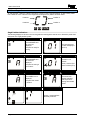
3.2 Icon Symbol Meanings
Disarmed Armed
Supply Personal Attack
Ready
Fire
Alarm Fault
Tamper
P1 P2
P3
P4
(( ))
Partitions
Rest of World Denmark, Norway, Finland & Sweden
Illuminated Correct AC & DC power sources AC power is OK
Blinking
DC source (battery) fault An AC fault
Extinguished
No AC power supplied to the panel No power to panel
Illuminated
OK to Arm, no open zones
Blinking
Select partitions to arm or disarm / Programming function is active
Extinguished
One or more open zones or all assigned partitions are already armed
Illuminated
Used in the Display Log function to qualify log information
Blinking
Active alarm in FTA mode. Digit display shows active zone
Extinguished
No alarm active
Illuminated
Indicates a tamper condition (used in log display)
Blinking
Indicates a tamper condition
Extinguished
No tamper alarm active
Illuminated
Indicates a PA alarm condition (used in log display)
Blinking
Indicates a PA alarm condition
Extinguished
No PA active
Illuminated
Indicates a Fire alarm condition (used in log display)
Blinking
Indicates a Fire alarm condition
Extinguished
No Fire alarm active
Illuminated
Indicates a system Fault
Blinking
Extinguished
No Fault active
Illuminated
The panel is armed
Blinking
The panel is arming with omitted zones
Extinguished
The panel is not armed
Illuminated
The panel is disarmed
Blinking
Extinguished
The panel is not disarmed
The P1, P2, P3 and P4 icons are used to show partition information as well as the partition segments.

Matrix User Guide
RINS915-2 Page: 5
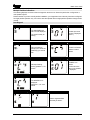
3.3 LCD Symbol Meanings
LCD KEYPAD
OK
REST OF THE WORLD DENMARK, NORWAY, FINLAND &
SWEDEN
Illuminated
CORRECT AC & DC POWER
SOURCES
AC
POWER IS OK
Blinking Indicates DC source (battery) fault Indicates an AC fault
Extinguished Indicates AC fault / no power to panel No power to the panel
Illuminated
Indicates a system Fault
Blinking Engineers mode active
Extinguished No Fault active
Illuminated
OK to Arm, no open zones
Blinking Select partitions to arm or disarm / Programming function is active
Extinguished One or more open zones or all assigned partitions are already armed
3.4 Proximity Reader LED meanings
PROXIMITY READER
STATUS LEDS
Supply
MULTIPARTITION SINGLE
PARTITION
PARTITION 4 ARM MODE D
PARTITION 3 ARM MODE C
PARTITION 2 ARM MODE B
Partition 1 Arm mode A
Illuminated
CORRECT AC & DC POWER SOURCES
Blinking Indicates DC source (battery) fault
Supply
Extinguished Indicates AC fault / no power to panel
Illuminated
PARTITION OR ARM MODE IS ARMED
Blinking Partition or Arm mode is in Alarm
Status
LEDs
Extinguished Partition or Arm mode is Disarmed

Matrix User Guide
Page 6 RINS915-2
3.5 Key fob Symbols and Meanings (KF4DW)
3.5.1 The KF4DW Actions
Action Description
Arm Mode A Arm the panel in Arm Mode A
Arm Mode B Arm the panel in Arm Mode B
Arm Mode C Arm the panel in Arm Mode C
Arm Mode D Arm the panel in Arm Mode D
Disarm Disarm the panel (if currently armed or in First to Alarm)
RKP Controlled Output RKP controlled output*
Keyfob Controlled Output Keyfob controlled output*
Fire Alarm Creates a Fire Alarm
Medical Alarm Creates a Medical Alarm
Personal Attack Creates a Personal Attack
Not Used No Action
Quick Arm Mode A Quick arm part set A**
Quick Arm Mode B Quick arm part set B**
Quick Arm Mode C Quick arm part set C**
Quick Arm Mode D Quick arm part set D**
*Note 1: Key fob Controlled is a new programmable output type that can be only be assigned to key fob button
presses.
*Note 2: Quick arm is a new arming method. It does not display open zones whilst arming.
All programmed button actions are on a per partition basis. This means that Partitions 1, 2, 3 & 4 can have
totally different sets of button actions from each other. This also means that key fobs assigned to users will only
be active in one partition (the first partition if assigned to multiple partitions).
3.5.2 STATUS LEDS
The status LED on the key fob shows the status of the panel when any arm or disarm button is pressed. The
indications are shown below:
Panel Status LED Indication
Disarmed
Green for 3 seconds
Arming
Toggles Green/Red in 3 second bursts until armed
Armed
Red for 3 seconds
In Alarm
Flashing Green for 3 seconds
In FTA (First To Alarm)
Flashing Green for 3 seconds
Status LED
LOCK Button
(Button 1)
I Button
(Button 3)
UNLOCK Button
(Button 2)
II Button
(Button 4)

Matrix User Guide
RINS915-2 Page: 7
3.6 Hidden Display Mode
The Matrix alarm panel incorporates a hidden display (confidential mode) feature that can be enabled / disabled
by your installation engineer.
This feature hides all of the panel information from the keypad display if the keypad has not been used for the
last 20 seconds. In hidden display only the supply icon will be shown on the Icon keypad, and only the time &
date and supply LED will be displayed on the LCD keypad.
The keypad will remain in hidden display mode until a valid user code has been entered on the keypad.
Depending in which state the alarm panel is currently in, the first valid user code entry whilst in hidden display
mode will have the following effects on the panel.
When Disarmed
If there are no system faults then the panel will come out of hidden display mode and automatically start the
arming process.
If there are any system faults pending then the keypad will drop out of hidden display mode and allow the
system fault to display. The panel will not start the arming process until you re-enter your user code again.
When Armed
The panel will leave hidden display mode and start the disarm process.
For single partition keypad / user combinations this will result in a full panel disarm.
When In Alarm
The panel leave hidden display mode and drop into First To Alarm (FTA) mode.
When In First To Alarm (FTA) mode
If the keypad is allowed to drop back into hidden display mode whilst in FTA mode, then simply enter your user
code again to re-display the FTA information.
NOTE: When in User Menu mode the keypad will drop out of the user menu and then into
hidden display mode if no keys are pressed for 20 seconds. As long as a key is pressed at
least once every 20 seconds then user mode will remain active. Care must be taken not to
keep pressing invalid keystrokes as this may cause the alarm panel to interpret this as a
key tamper attempt and force the panel into a tamper alarm.
3.7 Latching Alarms – Denmark, Norway, Finland & Sweden only
After each and every alarm event the panel will display a latched alarm indicator, until you reset the latched
alarm yourself, by either viewing the event log or by re-arming the panel.
Latched alarms are only displayed in day mode and are indicated by a fast flashing bell on the Icon keypad and
by the message VIEW THE LOG on the LCD keypad.
To clear the latched alarm indicator, you can either view the event log using the View Log user function, or
alternatively by fully re-arming the panel again.
If hidden display mode is enabled the keypad will not hide until the latched alarm is cleared.

Matrix User Guide
Page 8 RINS915-2
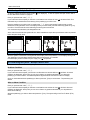
3.8 Arm Modes – Single Partition
Icon Keypad LCD Keypad
If a keypad is allocated to only one of the four
available partitions then the arm mode in which this
partition is armed will be displayed, assuming hidden
display mode is not active.
If a keypad is allocated to only one of the four
available partitions then the arm mode in which this
partition is armed will be displayed, assuming hidden
display mode is not active.
Alternatively, the arm mode message may be
displayed if enable by your Engineer.
Partition is armed in Mode A
TIME/DATE
ARM MODE A
Partition is armed in Mode B
TIME/DATE
ARM MODE B
Partition is armed in Mode C
TIME/DATE
ARM MODE C
Partition is armed in Mode D
TIME/DATE
ARM MODE D
Partition is arming with Omits
TIME/DATE
ARM MODE !A

Matrix User Guide
RINS915-2 Page: 9
3.9 Partition Indications
If your alarm panel has been configured at install time to have more than one partition, you may display single
or multiple partition information, depending on a variety of options programmed by your installer. If your keypad
has been configured for a single partition use only, then you will not display partition information, except in anti
code reset.
3.9.1 LCD Keypad – Multiple Partitions
The following status will be displayed for each partition of a common keypad, assuming hidden display mode is
not active:
I
Alarm
%
Arming ! Arming With Omits
&
Armed # Reset Required
All partitions are disarmed Partition 1 is arming or selected to be armed
Partition 1 is armed Partition 1 in alarm condition
Partition 1 Engineer / Anti-code reset required Partition 1 arming with omits

Matrix User Guide
Page 10 RINS915-2
3.9.2 Icon Keypad
As well as the P1 – P4 icons, partition information is shown on the 7-segment displays, as this is easily visible
from a distance. Each of the two corner segments are assigned to a partition as shown below.
Partition 1 Partition 2
Partition 3 Partition 4
P1 P2
P3
P4
Single Partition Indications
The following displays are shown on the Icon keypad when the keypad is used to arm or disarm the panel when
configured as a single-partition system.
Disarmed
In Alarm
The DISARMED and
OK icons are
displayed.
The panel is ready for
arming.
The last open zone
number is displayed.
(Zone 1)
Arming
First To Alarm (FTA)
The DISARMED and
OK icons are
displayed.
The panel is arming in
arm mode A
(( ))
The BELL icon
flashes.
Zone 1 was the First
zone To Alarm (FTA)
Armed
Arming with Omits
The ARMED icon is
displayed.
The panel has armed
in mode A
The armed icon
flashes indicating
that the panel is
arming with omitted
zones.
Anti-Code Reset / Engineer Reset
(( ))
P1
(( ))
Partition 1 segments flash
alternately as shown.

Matrix User Guide
RINS915-2 Page: 11
Multiple Partition Indications
The following displays are shown when the keypad is used to arm or disarm the panel when configured as a
multi-partition system.
Please note that if you have a multi-partition installation, your keypad and user code may have been configured
for single partition operation only. If this is the case then please refer to single partition operation throughout this
manual.
Icon Keypad
Disarmed
In Alarm
The DISARMED and
OK icons are displayed.
The panel is ready for
arming.
The last open zone
number is displayed.
(Zone 1)
Choose Partitions
Choose FTA
OK icon flashes to
prompt you to enter the
partition(s) you want to
arm.
The OK icon flashes.
Partition in alarm
flashes.
Arming
First To Alarm (FTA)
P1 P2
P3
OK stops flashing.
Arming partitions 1, 2 &
3 flash.
(( ))
The BELL icon
flashes.
The first zone into
alarm in the partition
is displayed
Armed
P1 P2
P3
The ARMED icon is
displayed.
Partitions 1, 2, & 3 are
armed.
Anti-Code Reset / Engineer Reset
(( ))
P1
(( ))
Partition segments flash
alternately as shown.

Matrix User Guide
Page 12 RINS915-2
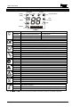
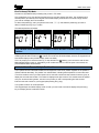
3.10 Displaying System Faults
3.10.1 Icon Keypad
When the Matrix detects a system fault, it displays the fault on the icon keypad (â). The fault takes the form of
a special symbol and a number. You can use this number to look up the actual fault by using the log table on
page 52. The system fault section of the log table has been repeated here for your convenience.
Example: System Fault 7
System Fault symbol
Fault number
Fault icon
When a system fault is displayed in day mode, the following table applies.
System Fault Description Icon
1 Bell fuse fail
â
2 Auxiliary fuse fail
â
3 Battery missing
â
4 Battery low voltage
â
5 Mains fail
â
6 Telephone line fail
â
7 Remote device has gone missing
â
8 Failed to report to central station
â
9 Battery fault on wireless expander
â
A Battery fault on keyfob(s)
â
B Jamming fault on wireless expander
â
C Detector signal low
â
D Detector signal has gone missing
â
While system faults are being displayed the keypad sounder periodically emits a low tone. This is to alert you to
the fault. Once you are aware of the fault you can silence the low tones by pressing the key once while the
fault is being displayed. If the fault is not cleared for a period of time then the sounder will re-start.
In hidden display mode the fault sounder cannot be silenced.
3.10.2 LCD Keypad
On an LCD keypad the system fault is automatically displayed on the display as shown below:
TIME/DATE
!BATTERY MISSING
While system faults are being displayed the keypad sounder periodically emits a low tone. This is to alert you to
the fault. Once you are aware of the fault you can silence the low tones by pressing the key once while the
fault is being displayed. If the fault is not cleared for a period of time then the sounder will re-start.
In hidden display mode the fault sounder cannot be silenced.
Note: If the keypad has entered hidden display mode, only the time and date will be
displayed.

Matrix User Guide
RINS915-2 Page: 13
3.11 Displaying Open Zones
While the panel is disarmed, any open zones will be displayed on the keypad (zone number on 7-segment
display on Icon keypad, zone name preceded by the ‘!’ symbol on LCD keypad), as long as this feature has
been enabled by your installer. Since the keypad can only display one open zone at a time, use the > and ?
keys to display other open zones.
3.12 Latching System Faults – Norway, Denmark, Finland &
Sweden
All system faults are latched. This means that once a system fault has been triggered, the display will continue
to display the fault even if the fault is eventually removed from the system. To clear the latched fault, first
remove the fault then view the event log.
Once you have entered and then left the View Log function, and if the system fault is no longer active, the
system fault message and the VIEW THE LOG indication will be removed from the display.
3.13 Latching Battery Fault
Battery faults may be latched if enabled by your installation engineer. This means that once a battery fault has
occurred, the display will continue to display the fault even if the cause of the fault has been removed from the
system.
In this case you will need to contact your installation engineer to clear the battery fault from the display.
If your installation engineer has allowed you to reset battery faults, then the Latching System Faults procedure
above will allow you to clear the fault as discussed.
3.14 Anti-code / Engineer Reset
If your installer has enabled anti-code or Engineer reset, after an alarm condition you will be unable to re-arm
the panel until a reset code has been entered.
Icon Keypad
(( ))
P1
(( ))
LCD Keypad
Single Partition Multiple Partitions
Press the C key to display the anti-code seed number. This should be passed on to your central monitoring
station, who will in turn provide you with a corresponding reset code.
Enter the code on your keypad.
The system will return to normal operation.

Matrix User Guide
Page 14 RINS915-2
CHAPTER 4: ARMING / DISARMING THE SYSTEM
This section details how to arm and disarm a Matrix system using both the Icon and LCD keypads. As with most
Matrix features there are always possible variations depending on how the Matrix features have been
programmed by your installer.
These instructions assume the default user code (TUV) is being used to arm/disarm the panel. If your user
code is different, then substitute your user code in place of the one described here.
4.1 Icon Keypad
4.1.1 Arming – Single Partition User
To arm the system all zones must be closed (y icon displayed). To arm the system with open zones, refer to
the Arm With Omits function on page 26.
Enter you personal user code TUV.
If your code has been accepted, you will hear a confirmation tone and the system will start arming in arm mode
A. The exit tones will sound indicating that arming has commenced.
To change the arm mode press the C key followed by the arm mode you require (A, B, C or D). The system will
re-configure for the new arm mode.
You must leave the premises by the designated route.
At the end of the exit timer the system will arm.
Some installations require that a push button switch be pressed before the panel finally arms.
Disarmed
Arming
Armed
4.1.2 Displaying the Armed Status
Once the system has armed, the Icon keypad will either display the arm mode (A, B, C or D), or it will display
nothing at all. This depends on how the Matrix features have been programmed by your installer.
If hidden display mode is enabled only the supply icon ({) will operate.
4.1.3 Disarming the System – Single Partition User
Enter you personal user code TUV.
No Alarm Condition
If your code has been accepted, you will hear a confirmation tone and the system will disarm. The Icon keypad
will revert to normal day mode operation.
After an Alarm Condition
If your code has been accepted, you will hear a confirmation tone and the system will go into First To Alarm
(FTA) mode.

Matrix User Guide
RINS915-2 Page: 15
First To Alarm (FTA) Mode
The bell icon (z) flashes slowly indicating that you are in FTA mode. This mode allows you to view the first
zone that went into, and thus caused, the alarm. If the keypad enters hidden display mode whilst in FTA mode,
simply re-enter your user code to re-display the FTA information.
To fully disarm, enter you personal user code TUV. If your code has been accepted, you will hear a
confirmation tone and the system will disarm. The ICON keypad display will revert to normal day mode
operation.
Alarm (Zone 1) FTA (Zone 1) Disarmed
(( ))
4.1.4 Latched Alarm Condition – Denmark, Finland, Norway & Sweden Only
A special indication will appear on the ICON display after any valid alarm has been successfully disarmed. The
ICON keypad will flash the bell icon (z) at twice the normal rate. Whilst this display is active, the keypad will not
enter hidden display mode (if hidden display mode is enabled).
This is to prompt you to check the event log. To stop the bell icon (z) flashing you must use the user function
View Log described on page 27. Alternatively, enter a valid user code to re-arm the panel. Once armed, the
previous latched alarm will be cleared.
4.1.5 Anti-Code Reset
If your system has anti code reset enabled, the top left partition segments will flash alternately. The P1 icon will
also flash, indicating that partition 1 is in anti-code reset.
You will be unable to re-arm your alarm panel until an anti-code number has been entered. Press the C key to
display the anti code seed number. The number is displayed one digit at a time. This number should be passed
onto your central monitoring station, who will in turn provide you with a corresponding anti code number.
Enter this anti code number on your keypad (after pressing the C key).
Your system will return to normal operation.
If the keypad drops into hidden display mode, re-enter your user code to unhide the display and press the C
key to re-display the anti-code seed number.

Matrix User Guide
Page 16 RINS915-2
4.1.6 Arming – Multiple Partition User
To arm the system all zones must be closed, (y icon displayed). To arm the system with open zones, refer to
the Arm With Omits function on page 26.
Enter you personal user code TUV.
If your code has been accepted you will hear a confirmation tone and the OK icon (y) will start to flash. This
indicates that you should enter the number(s) of the partition(s) you wish to arm.
Enter the partition(s) you wish to arm by pressing the - V keys on the keypad. Partitions that you have
selected for arming will flash on the icon display. When you have made your final selection(s) press the key
to confirm. The exit tones will sound indicating that arming has commenced.
You must leave the premises by the designated route.
At the end of the exit timer the system will arm. Some installations require that a push button switch be pressed
before the panel finally arms.
Disarmed Select Partitions Arming Armed
P1 P2
P3
P1 P2
P3
4.1.7 Displaying the Armed Status – Multiple Partition User
Once the system is armed the icon keypad will either display the armed partitions or it will display nothing at all.
This depends on how the Matrix features have been programmed by your installer.
If hidden display mode is enabled only the supply icon ({) will operate.
4.1.8 Disarming the System – Multiple Partition User
This section describes how to disarm your system under various panel states.
No Alarm Condition
Enter you personal user code TUV.
If your code has been accepted, you will hear a confirmation tone and the OK icon (y) will flash. All armed
partitions are displayed. At this point you can arm or disarm any partitions allocated to you. Select the
partition(s) you wish to disarm. The selected partition segments will be removed from the icon display.
Once you have selected all the partition(s) to disarm, press the key to confirm them. The partition(s) will
disarm.
After an Alarm Condition
Enter you personal user code TUV.
If your code has been accepted you will hear a confirmation tone and the OK icon (y) will flash. All armed
partitions are displayed. At this point you can arm or disarm any partitions allocated to you. All partitions in
alarm will be flashing.
Select the partition(s) you wish to disarm and press the key. The system will go into First To Alarm (FTA)
mode.
La pagina si sta caricando...
La pagina si sta caricando...
La pagina si sta caricando...
La pagina si sta caricando...
La pagina si sta caricando...
La pagina si sta caricando...
La pagina si sta caricando...
La pagina si sta caricando...
La pagina si sta caricando...
La pagina si sta caricando...
La pagina si sta caricando...
La pagina si sta caricando...
La pagina si sta caricando...
La pagina si sta caricando...
La pagina si sta caricando...
La pagina si sta caricando...
La pagina si sta caricando...
La pagina si sta caricando...
La pagina si sta caricando...
La pagina si sta caricando...
La pagina si sta caricando...
La pagina si sta caricando...
La pagina si sta caricando...
La pagina si sta caricando...
La pagina si sta caricando...
La pagina si sta caricando...
La pagina si sta caricando...
La pagina si sta caricando...
La pagina si sta caricando...
La pagina si sta caricando...
La pagina si sta caricando...
La pagina si sta caricando...
La pagina si sta caricando...
La pagina si sta caricando...
La pagina si sta caricando...
La pagina si sta caricando...
La pagina si sta caricando...
La pagina si sta caricando...
La pagina si sta caricando...
La pagina si sta caricando...
La pagina si sta caricando...
La pagina si sta caricando...
La pagina si sta caricando...
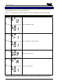
-
 1
1
-
 2
2
-
 3
3
-
 4
4
-
 5
5
-
 6
6
-
 7
7
-
 8
8
-
 9
9
-
 10
10
-
 11
11
-
 12
12
-
 13
13
-
 14
14
-
 15
15
-
 16
16
-
 17
17
-
 18
18
-
 19
19
-
 20
20
-
 21
21
-
 22
22
-
 23
23
-
 24
24
-
 25
25
-
 26
26
-
 27
27
-
 28
28
-
 29
29
-
 30
30
-
 31
31
-
 32
32
-
 33
33
-
 34
34
-
 35
35
-
 36
36
-
 37
37
-
 38
38
-
 39
39
-
 40
40
-
 41
41
-
 42
42
-
 43
43
-
 44
44
-
 45
45
-
 46
46
-
 47
47
-
 48
48
-
 49
49
-
 50
50
-
 51
51
-
 52
52
-
 53
53
-
 54
54
-
 55
55
-
 56
56
-
 57
57
-
 58
58
-
 59
59
-
 60
60
-
 61
61
-
 62
62
-
 63
63


Pyronix Matrix 832 Manuale utente
- Tipo
- Manuale utente
- Questo manuale è adatto anche per
in altre lingue
- English: Pyronix Matrix 832 User manual
Documenti correlati
Altri documenti
-
PARADOX Esprit+ 642 Installer's Manual
-
ADEMCO Vista-20PCN Manuale utente
-
Risco Agility Manuale utente
-
Aritech CS-175-275-575 Series Manuale utente
-
Bentel Security Absoluta Quick User Manual
-
Crow RUNNER 8/64 Guida d'installazione
-
Aritech CS350 Installation Instructions Manual
-
-
-
Honeywell EKZ008200B Manuale utente