
MT5600BA/BL Series
MT5600BA–V.92
MT5600BA–V.90
MT5600BL–V.90
Data/Fax Modem
User Guide

2
Multi-Tech Systems, Inc. MT5600BA/BL Series User Guide (S000276E)
MultiModemII User Guide
MT5600BA–V.92, MT5600BA–V.90, MT5600BL–V.90
P/N S000276E Revision E
©2002-2004 by Multi-Tech Systems, Inc.
All rights reserved. This publication may not be reproduced, in whole or in part, without prior expressed
written permission from Multi-Tech Systems, Inc.
Multi-Tech Systems, Inc. makes no representations or warranties with respect to the contents hereof and
specifically disclaims any implied warranties of merchantability or fitness for any particular purpose.
Furthermore, Multi-Tech Systems, Inc. reserves the right to revise this publication and to make changes
in the content hereof without obligation of Multi-Tech Systems, Inc. to notify any person or organization of
such revisions or changes.
Record of Revisions
Revision Date Description
A 10/03/02 Initial release of MT5600BA Global V.92. (Also replaces S0000129 Rev. C - the
MT5600BA/BL User Guide).
B 02/17/03 Changed cover. Changed text to indicate that the following
are
implemented:
V.25bis HDLC NRZ?
,
V.25bis HDLC NRZI?
,
and V.25bis BISYNC
C 07/31/03 Added setting the country code using the LCD panel. Add country codes list.
D 05/28/04 Change the word to
country
to
country or region
.
E 12/09/04 Add Web site location of the country/region code list.
Trademarks
MultiModemII, Multi-Tech, and the Multi-Tech logo are trademarks of Multi-Tech Systems, Inc.
Adobe and Acrobat are trademarks of Adobe Systems Incorporated. Microsoft, Windows, Windows 98/
Me/NT/2000/XP are either registered trademarks or trademarks of Microsoft Corporation in the United
States and/or other countries. All other brand and product names mentioned in this publication are
trademarks or registered trademarks of their respective companies.
Warranty
For Multi-Tech Warranty, see Multi-Tech Web site at http://www.multitech.com/COMPANY/Policies/warranty/
Patents
This device is covered by one or more of the following patents: 6,031,867; 6,012,113; 6,009,082;
5,905,794; 5,864,560; 5,815,567; 5,815,503; 5,812,534; 5,809,068; 5,790,532; 5,764,628; 5,764,627;
5,754,589; 5,724,356; 5,673,268; 5,673,257; 5,644,594; 5,628,030; 5,619,508; 5,617,423; 5,600,649;
5,592,586; 5,577,041; 5,574,725; 5,559,793; 5,546,448; 5,546,395; 5,535,204; 5,500,859; 5,471,470;
5,463,616; 5,453,986; 5,452,289; 5,450,425; D353,598; 5,355,365; 5,309,562; 5,301,274. Other patents
pending.
World Headquarters
Multi-Tech Systems, Inc.
2205 Woodale Drive
Mounds View, MN 55112 U.S.A
Technical Support
Country By Email By Phone
Europe, Middle East, Africa: [email protected] +(44) 118 959 7774
U.S., Canada, all others: [email protected] (800) 972-2439 or (763) 717-5863
Internet Address: http://www.multitech.com

3
MultiModemII User Guide Table of Contents
Multi-Tech Systems, Inc. MT5600BA/BL Series User Guide (S000276E)
Table of Contents
Chapter 1 - Description and Features ......................................................................... 5
Product Description .............................................................................................. 5
About AT Commands ........................................................................................... 5
Features ............................................................................................................... 5
Safety Warnings................................................................................................... 6
Chapter 2 - Installation ............................................................................................... 7
Step 1 - Connect the Modem to Your System ...................................................... 7
Step 2 - Install the Modem Driver ......................................................................... 9
Removing an Old Modem Driver .......................................................................... 9
Step 3 - Setting Your Country or Region Code ................................................... 10
Step 4 - Install PhoneTools ................................................................................ 11
Chapter 3 - Using the Front Panel ............................................................................ 12
Modem Configuration ......................................................................................... 12
LED Indicators ................................................................................................... 12
Liquid Crystal Display (LCD) .............................................................................. 13
Option Selection .......................................................................................... 13
Menu Structure ............................................................................................ 13
Menu Overview .................................................................................................. 14
Status Trunk ................................................................................................. 15
Basic Options Trunk ..................................................................................... 16
Advanced Options Trunk .............................................................................. 18
Remote Configuration Options Trunk ........................................................... 20
Diagnostic Options Trunk ............................................................................. 20
Phone Number Memory Options Trunk ........................................................ 21
Caller ID Options Trunk ................................................................................ 21
Menu Options .............................................................................................. 22
Status .......................................................................................................... 22
Basic Options .............................................................................................. 23
Advanced Options ....................................................................................... 25
Remote Configuration Options..................................................................... 27
Diagnostic Options ...................................................................................... 27
Phone Number Memory Options ................................................................. 27
Caller ID Options ......................................................................................... 28
Chapter 4 - Leased Line Operation .......................................................................... 29
Two-Wire Setup ................................................................................................. 29
Four-Wire Setup ................................................................................................. 30
Dial Backup and Leased-Line Restoral .............................................................. 31
Dial Backup and Leased Line Restoral Setup .................................................... 31
Chapter 5 - Remote Configuration ............................................................................ 33
Basic Procedure................................................................................................. 33
Setup ................................................................................................................. 33
Changing the Remote Configuration Password.................................................. 33
Changing the Remote Escape Character ........................................................... 34
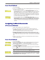
Chapter 6 - Callback Security ................................................................................... 35
Setup Procedures .............................................................................................. 35
Turning Callback Security On and Off ................................................................ 35
Assigning Callback Passwords .......................................................................... 36
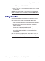
Calling Procedure .............................................................................................. 38
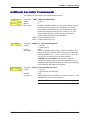
Callback Security Commands ............................................................................ 39
Callback Assignments Form .............................................................................. 40

4
MultiModemII User Guide Table of Contents
Multi-Tech Systems, Inc. MT5600BA/BL Series User Guide (S000276E)
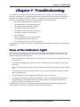
Chapter 7 - Troubleshooting ..................................................................................... 41
None of the Indicators Light ............................................................................... 41
The Modem Does Not Respond to Commands .................................................. 42
The Modem Cannot Connect When Dialing ....................................................... 43
The Modem Disconnects While Online .............................................................. 44
The Modem Cannot Connect When Answering ................................................. 45
File Transfer Is Slower Than It Should Be .......................................................... 45
Data Is Being Lost .............................................................................................. 45
There Are Garbage Characters on the Monitor .................................................. 46
The Modem Doesn’t Work with Caller ID ........................................................... 46
Fax and Data Software Can’t Run at the Same Time ......................................... 46
Appendix A - Regulatory Compliance ....................................................................... 47
FCC Part 68 Telecom ........................................................................................ 47
Fax Branding Statement .................................................................................... 48
Canadian Limitations Notice............................................................................... 48
EMC, Safety, and R&TTE Directive Compliance ................................................ 49
International Modem Restrictions ....................................................................... 49
New Zealand Telecom Warning Notice .............................................................. 49
South African Notice .......................................................................................... 50
Appendix B - Technical Specifications ...................................................................... 51
Appendix C - Upgrading the Firmware...................................................................... 53
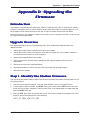
Introduction ........................................................................................................ 53
Upgrade Overview ............................................................................................. 57
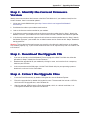
Step 1 - Identify the Modem Firmware ............................................................... 57
Step 2 - Identify the Current Firmware Version .................................................. 58
Step 3 - Download the Upgrade File .................................................................. 58
Step 4 - Extract the Upgrade Files ..................................................................... 58
Step 5 - Clear Your Stored Paramenters............................................................ 59
Step 6 - Upgrade the Modem’s Firmware........................................................... 59
Step 7 - Restore Your Parameters ..................................................................... 59
Appendix D - Installing a Modem Under Linux .......................................................... 60
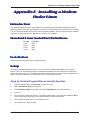
Introduction ........................................................................................................ 60
Standard Linux Serial Port Definitions ................................................................ 60
Installation .......................................................................................................... 60
Setup ................................................................................................................. 60
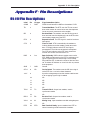
Appendix E - Pin Descriptions .................................................................................. 62
RS-232 Pin Descriptions .................................................................................... 62
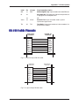
RS-232 Cable Pinouts........................................................................................ 63
Leased Line Pinouts........................................................................................... 64
Index ........................................................................................................................ 65

5
Chapter 1 - Description and Features
Multi-Tech Systems, Inc. MT5600BA/BL Series User Guide (S000276E)
CC
CC
C
hapterhapter
hapterhapter
hapter
1 - Descr 1 - Descr
1 - Descr 1 - Descr
1 - Descr
iptipt
iptipt
ipt
ii
ii
i
oo
oo
o
n andn and
n andn and
n and
FF
FF
F
ee
ee
e
aa
aa
a
tt
tt
t
urur
urur
ur
eses
eses
es
Congratulations on your purchase of the MultiModemII modem. You have acquired one of the finest
intelligent data/fax modems available today from one of the world’s oldest modem manufacturers: Multi-
Tech Systems, Inc. This user guide will help you install, configure, test and use your modem.
PP
PP
P
rr
rr
r
oductoduct
oductoduct
oduct
Descr Descr
Descr Descr
Descr
iptipt
iptipt
ipt
ii
ii
i
oo
oo
o
nn
nn
n
This modem supports two-wire and/or four-wire leased lines. The four-wire leased line includes the dial
backup and automatic leased line restoration features. Please note that, because leased-line operation
consists of two client modems connected to each other, the maximum leased line data rate is 33.6K bps.
The MT5600BA-V.92 modem supports both two-wire and four-wire leased lines.
The MT5600BA modem supports a two-wire leased line.
The MT5600BL modem supports a four-wire leased line.
The MultiModemII offers interactive automatic dialing. You can store four command lines or telephone
numbers of up to 30 characters each in the modem’s nonvolatile memory. The modem pulse- or tone-
dials, and recognizes dial tones and busy signals for reliable call-progress detection. It can also detect
AT&T calling card tones. It is FCC-registered for connection to telephone networks without notification to
the telephone company.
The MultiModemII front panel includes a liquid crystal display and four buttons, which together can be
used to either display the current connection status of the modem or to configure the modem. The
MultiModemII also can be configured through standard AT commands.
AA
AA
A
boutbout
boutbout
bout
AA
AA
A
TT
TT
T
C C
C C
C
oo
oo
o
mmmm
mmmm
mm
andsands
andsands
ands
AT Commands for this product are published in a separate document and included on the
MT5600BA/BL System CD that accompanies your modem.
FF
FF
F
ee
ee
e
aa
aa
a
tt
tt
t
urur
urur
ur
eses
eses
es
General
•
Complies with major international standards to ensure compatibility with other modems.
•
Uses DTMF and tone detection to distinguish data and fax calls when used with software that
supports these features.
•
Supports serial port speeds to 230.4K bps with compatible serial ports
•
Supports Caller ID (North American versions only).
•
Displays status and configuration information on a front panel LCD.
Data
•
Supports automatic fallback to slower speeds in noisy line conditions, and fall-forward to faster
speeds as conditions improve.
•
Supports both synchronous and asynchronous data transfer.
•
Support two-wire leased line operation. Also supports four-wire leased line operation with dial
backup and leased line restoration.
•
Supports callback security and remote configuration.
•
Supports AS400 applications.
•
Automatically disables compression when transferring already-compressed files.
•
Can autodial, redial, pulse (rotary) and touch-tone dial.
•
Detects dial tones and busy signals for reliable call-progress detection.
•
Compatible with the standard AT command set used by most communication programs.
•
Supports Plug and Play (PnP).
•
Can be flash upgraded.
Fax
•
Supports V.17, Class 1, and Group 3 fax standards, (V.92 support Class 2 also) allowing it to
communicate with other fax modems as well as with fax machines.

6
Chapter 1 - Description and Features
Multi-Tech Systems, Inc. MT5600BA/BL Series User Guide (S000276E)
SS
SS
S
afaf
afaf
af
etet
etet
et
yy
yy
y
WW
WW
W
arar
arar
ar
ningning
ningning
ning
ss
ss
s
• Use this product only with UL- and CUL-listed computers.
• To reduce the risk of fire, use only 26 AWG or larger telephone wiring.
• Never install telephone wiring during a lightning storm.
• Never install a telephone jack in a wet location unless the jack is specifically designed for wet
locations.
• Never touch uninsulated telephone wires or terminals unless the telephone line has been
disconnected at the network interface.
• Use caution when installing or modifying telephone lines.
• Avoid using a telephone during an electrical storm; there is a risk of electrical shock from
lightning.
• Do not use a telephone in the vicinity of a gas leak.

7
Chapter 2 - Installation
Multi-Tech Systems, Inc. MT5600BA/BL Series User Guide (S000276E)
CC
CC
C
hapterhapter
hapterhapter
hapter
2 - Inst 2 - Inst
2 - Inst 2 - Inst
2 - Inst
alal
alal
al
lala
lala
la
tt
tt
t
ii
ii
i
oo
oo
o
nn
nn
n
Step 1 - CStep 1 - C
Step 1 - CStep 1 - C
Step 1 - C
oo
oo
o
nnenne
nnenne
nne
ctct
ctct
ct
t t
t t
t
he Modhe Mod
he Modhe Mod
he Mod
em to em to
em to em to
em to
YY
YY
Y
ourour
ourour
our
Sy Sy
Sy Sy
Sy
stemstem
stemstem
stem
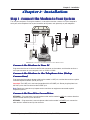
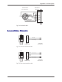
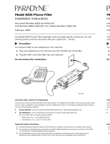
Turn off your computer. Placing the modem in a convenient location, connect it to your computer’s
serial port, to the telephone line, to your leased line, to AC power, and, optionally, to your telephone.
VOLUME
EIA RS232C
LEASEDLINE
POWER
PHONE
or
MultiModemII connections with V.92 transformer and V.90 transformer.
CC
CC
C
oo
oo
o
nnenne
nnenne
nne
ctct
ctct
ct
t t
t t
t
he Modhe Mod
he Modhe Mod
he Mod
em to em to
em to em to
em to
YY
YY
Y
ourour
ourour
our
PC PC
PC PC
PC
Plug one end of the serial cable into the RS-232 connector on the modem, and the other end into a
serial port connector on your computer, such as COM1 or COM2.
CC
CC
C
oo
oo
o
nnenne
nnenne
nne
ctct
ctct
ct
t t
t t
t
he Modhe Mod
he Modhe Mod
he Mod
em to tem to t
em to tem to t
em to t
he he
he he
he
TT
TT
T
elephoelepho
elephoelepho
elepho
ne Line (ne Line (
ne Line (ne Line (
ne Line (
DialupDialup
DialupDialup
Dialup
CC
CC
C
oo
oo
o
nnenne
nnenne
nne
ctct
ctct
ct
ii
ii
i
oo
oo
o
n)n)
n)n)
n)
Plug one end of the modular phone cable into the modem’s LINE jack, and the other end into a public
switched telephone network (PSTN) wall jack.
Important: The LINE jack is not interchangeable with the PHONE jack. Do not plug the phone into
the LINE jack or the line cable into the PHONE jack.
Note: Regulatory agencies may impose certain restrictions on equipment connected to public
telephone systems.
CC
CC
C
oo
oo
o
nnenne
nnenne
nne
ctct
ctct
ct
t t
t t
t
heTheT
heTheT
heT
ww
ww
w
o-o-
o-o-
o-
WW
WW
W
irir
irir
ir
e Le L
e Le L
e L
ee
ee
e
ased Lineased Line
ased Lineased Line
ased Line
MT5600BA – Plug one end of a two-wire phone cable into the modem’s LINE jack; connect the other
end to a leased line wall jack or terminals.
MT5600BL – Plug one end of a two-wire phone cable into the modem’s LEASED jack; connect the
other end to a leased line wall jack or terminals.

8
Chapter 2 - Installation
Multi-Tech Systems, Inc. MT5600BA/BL Series User Guide (S000276E)
CC
CC
C
oo
oo
o
nnenne
nnenne
nne
ctct
ctct
ct
t t
t t
t
he Fhe F
he Fhe F
he F
our-our-
our-our-
our-
WW
WW
W
irir
irir
ir
e Le L
e Le L
e L
ee
ee
e
ased Lineased Line
ased Lineased Line
ased Line
MT5600BL Only – Plug one end of a four-wire phone cable into the modem's LEASED jack; connect
the other end to a four-wire leased line wall jack or terminals.
Modems with a leased-line jack support the dial backup feature. For dial backup operation, plug one
end of your dialup modular phone cable into the modem’s
LINE jack and the other end into a PSTN
wall jack.Plug one end of a two-wire or four-wire phone cable into the modem’s LEASED jack, and
connect the other end to a leased-line wall jack or terminals.
Modems with a leased-line jack support the dial backup feature. For dial backup operation, plug one
end of your dialup modular phone cable into the modem’s LINE jack and the other end into a PSTN
wall jack.
CC
CC
C
oo
oo
o
nnenne
nnenne
nne
ctct
ctct
ct
t t
t t
t
he Phohe Pho
he Phohe Pho
he Pho
ne to tne to t
ne to tne to t
ne to t
he Modhe Mod
he Modhe Mod
he Mod
em (Optem (Opt
em (Optem (Opt
em (Opt
ii
ii
i
oo
oo
o
nal)nal)
nal)nal)
nal)
For voice-only calls, plug a telephone into the modem’s PHONE jack.
CC
CC
C
oo
oo
o
nnenne
nnenne
nne
ctct
ctct
ct
t t
t t
t
he Modhe Mod
he Modhe Mod
he Mod
em to tem to t
em to tem to t
em to t
he he
he he
he
AA
AA
A
C PC P
C PC P
C P
oo
oo
o
ww
ww
w
erer
erer
er
O O
O O
O
utut
utut
ut
letlet
letlet
let
Plug the power transformer into an AC power outlet or power strip. Plug the power transformer’s
cable into the POWER jack on the modem.
Note: Use only the power transformer supplied with the modem. Use of any other transformer voids
the warranty and can damage the modem.
PP
PP
P
oo
oo
o
ww
ww
w
er-er-
er-er-
er-
On On
On On
On
TT
TT
T
estest
estest
est
Test the modem by turning it on (a power switch is located on the front panel). When you apply
power, the modem performs a diagnostic self-test, indicated by the TM indicator lighting for a few
seconds, after which the LCD should light. If this does not happen, check that the power switch is
on, the power transformer is solidly connected, and the AC outlet is live. If these measures do not
work, see the “Troubleshooting” chapter.

9
Chapter 2 - Installation
Multi-Tech Systems, Inc. MT5600BA/BL Series User Guide (S000276E)
Step 2 - InstStep 2 - Inst
Step 2 - InstStep 2 - Inst
Step 2 - Inst
alal
alal
al
l tl t
l tl t
l t
he Modhe Mod
he Modhe Mod
he Mod
em Drem Dr
em Drem Dr
em Dr
iviv
iviv
iv
erer
erer
er
If you use Windows 98/Me/NT 4.0/2000/XP; you must install the modem driver. The drivers are installed
easily since Windows supports Plug-and-Play.
InstInst
InstInst
Inst
alal
alal
al
ling tling t
ling tling t
ling t
he Modhe Mod
he Modhe Mod
he Mod
em Drem Dr
em Drem Dr
em Dr
iviv
iviv
iv
erer
erer
er
f f
f f
f
oo
oo
o
rr
rr
r
WW
WW
W
indind
indind
ind
oo
oo
o
ww
ww
w
s 98/Me/2000/s 98/Me/2000/
s 98/Me/2000/s 98/Me/2000/
s 98/Me/2000/
XX
XX
X
PP
PP
P
1. Make sure your modem is connected properly, and then turn on your computer. Windows should
detect your new modem and open the Install New Modem wizard.
Note: If Windows cannot find a modem, your modem may be turned off, it may be plugged into
the wrong connector on your computer, or the serial cable may be faulty. See “None of the LEDs
Light When the Modem Is Turned On” and “The Modem Does Not Respond to Commands” in the
“Troubleshooting” chapter.
2. Insert the MultiModemII system CD into your CD-ROM drive, and then click OK.
3. Windows installs and configures the modem.
4. Click Finish to exit.
InstInst
InstInst
Inst
alal
alal
al
ling tling t
ling tling t
ling t
he Modhe Mod
he Modhe Mod
he Mod
em Drem Dr
em Drem Dr
em Dr
iviv
iviv
iv
erer
erer
er
f f
f f
f
oo
oo
o
rr
rr
r
WW
WW
W
indind
indind
ind
oo
oo
o
ww
ww
w
s Ns N
s Ns N
s N
TT
TT
T
1. Make sure your modem is connected properly, and then turn on your computer. Windows should
detect your new modem and open the Install New Modem wizard.
Note: If Windows cannot find a modem, your modem may be turned off, it may be plugged into
the wrong connector on your computer, or the serial cable may be faulty. See “None of the LEDs
Light When the Modem Is Turned On” and “The Modem Does Not Respond to Commands” in the
Troubleshooting chapter of the User Guide.
2. In the Install New Modem wizard, select Don’t detect my modem; I will select it from a list,
and then click Next. A dialog box with a list of manufacturers and a list of modem models
appears.
3. Insert the MultiModemII system CD into your CD-ROM drive, and then click Have Disk.
4. In the Install from Disk dialog box, select the drive that the CD is in, and then click OK.
5. A list of modems appears. Select your modem and click Next.
6. Select the port that the modem is connected to, and then click Next.
7. Windows installs and configures the modem.
8. Click Finish to exit.
RR
RR
R
emoemo
emoemo
emo
vv
vv
v
ing an Old Moding an Old Mod
ing an Old Moding an Old Mod
ing an Old Mod
em Drem Dr
em Drem Dr
em Dr
iviv
iviv
iv
erer
erer
er
When your new modem replaces another modem, the old modem driver remains in Windows, and the
old modem driver is still selected in HyperTerminal and other Windows applications. Though you can
change the application connection descriptions one at a time, it is easier to force Windows applications to
use the new modem by removing the old modem driver from Windows.
1. Click the Start button, point to Settings, and click Control Panel.
2. Double-click the Modems icon to open the Modems Properties dialog box.
3. In the list box, select the old modem.
4. Click Remove, and then click Close.
5. The next time you dial a HyperTerminal connection, it will select your new modem and ask you to
confirm the selection.

10
Chapter 2 - Installation
Multi-Tech Systems, Inc. MT5600BA/BL Series User Guide (S000276E)
Step 3 - SetStep 3 - Set
Step 3 - SetStep 3 - Set
Step 3 - Set
tt
tt
t
ing ing
ing ing
ing
YY
YY
Y
ourour
ourour
our
C C
C C
C
ountount
ountount
ount
rr
rr
r
yy
yy
y
o o
o o
o
rr
rr
r
R R
R R
R
egeg
egeg
eg
ii
ii
i
oo
oo
o
n Cn C
n Cn C
n C
odod
odod
od
ee
ee
e
(MT5600B(MT5600B
(MT5600B(MT5600B
(MT5600B
AA
AA
A
––
––
–
VV
VV
V
..
..
.
99
99
9
2 Only)2 Only)
2 Only)2 Only)
2 Only)
The MT5600BA-V.92 modem is a global modem - it can be used all over the world.
However, countries or regions vary in their requirements for how a modem functions. Therefore, you
must configure yours to match the defaults of the country or region in which you are using it. Choose
from any of the three methods:
• Using the LCD Panel to Set Your Country or Region Code
• Using the Global Wizard to Set Your Country or Region Code
• Using AT Commands to Set Your Country or Region Code
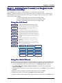
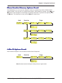
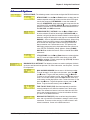
Using tUsing t
Using tUsing t
Using t
he Lhe L
he Lhe L
he L
CD PCD P
CD PCD P
CD P
anel anel
anel anel
anel
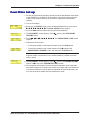
Region Profile
Region Profile
question mark represents the question Is this the region
not the one you want, arrow across until you see the code
Region Profile
Region Profile
Status
Basic Options
Advanced
Options
Remote Config
Diagnostics
Phone Number
Memory
Region Select
Caller ID
Region Setting
Options B5?
Region Profile
99?
Region Profile
01? 02?
Region Profile
03?
Region Profile
04?
1. Start at the Status LCD and use the down arrow to
move down the menu tree to the Region Select LCD.
4.When you reach the region code you want, press
Enter. After pressing Enter, you will see the message
Option Set
.
2. Use the right arrow to move from the Region Select
LCD, across the Region Setting Options LCD, to the
Current Setting LCD.
3. If the current setting shown is not the one for your
region, arrow across to the Region Profile LCD. The
you want? If B5 is the one you want, press Enter; if it s
you desire. See the list of Region Codes on the back of
this card.
Current Setting
5. After setting the region profile, you can re-power the
modem or use the arrows to move back and up the menu
tree to return to the Status LCD.
00?
Region Profile
09?
Region Profile
6C? 9F?
Using tUsing t
Using tUsing t
Using t
he Glohe Glo
he Glohe Glo
he Glo
bal bal
bal bal
bal
WW
WW
W
iziz
iziz
iz
arar
arar
ar
dd
dd
d
The Global Wizard configuration utility is recommended for computers running in Windows. The
Wizard can configure your modem for a specific country or region with just a few mouse clicks.
1. Insert the MultiModemII CD into the CD-ROM drive. The Autorun dialog box appears.
2. Click Initial Setup and Country or Region Selection. The Global Wizard dialog box
appears. Click Next.
3. The Global Wizard searches for your modem and identifies it. Click Next after your modem is
identified.
4. Select the country or region in which the modem will be used. Click Next.
5. Review your choice. If it is correct, click Next to configure the modem.
6. When the Global Wizard announces that the parameters have been set, click Finish to exit.

11
Chapter 2 - Installation
Multi-Tech Systems, Inc. MT5600BA/BL Series User Guide (S000276E)
Using Using
Using Using
Using
AA
AA
A
TT
TT
T
C C
C C
C
oo
oo
o
mmmm
mmmm
mm
andsands
andsands
ands
If you are comfortable using AT commands, you can use them to configure your modem. You
must enter these commands in your communication program's terminal window. You can use a
communication program such as PhoneTools. See Step 4 below.
How to Change the Country/Region Code
1. View the list of available country/region codes to find your country/region code by
executing the command AT +GCI? <CR>
Note: A list of country/region codes is also available on the Multi-Tech Web site at:
http://www.multitech.com/PRODUCTS/Categories/Modems/global/
configuration.asp#chart
2. Set and save the code by executing the following command:
AT+GCI=
nn
<CR> (where
nn
is the country/region code).
3. OK displays.
4. The code then displays.
How to Verify the Code
1. Type AT+GCI?<CR>
or you can use this command:
ATI5<CR>
Example
1. Type AT+GCI=B5<CR> to set B5 as your country/region code.
2. Type AT+GCI?<CR> or ATI5<CR> to verify that B5 was set.
B5 indicates the configuration is set for any B5 country such as Canada and the United
States.
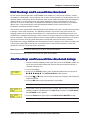
Step 4 - InstStep 4 - Inst
Step 4 - InstStep 4 - Inst
Step 4 - Inst
alal
alal
al
l Phol Pho
l Phol Pho
l Pho
neTneT
neTneT
neT
oooo
oooo
oo
ll
ll
l
ss
ss
s
Note: PhoneTools may or may not be included on the MultiModemII CD according to your company's
preference.
Data communications software gives you access to commands that govern how the modem operates;
that is, how the modem handles incoming and outgoing data streams, etc.
MultiTech includes a data communications software package (PhoneTools) on the product CD shipped
with your modem. In general, the modem will work with most data communications software packages.
1. Insert the MultiModemII CD into your CD-ROM drive. Allow Autorun to bring up the introductory
screen.
2. Click on the PhoneTools icon and choose the appropriate language.
3. Follow the PhoneTools installation wizard. No input is needed. You may choose to view the
“Readme” file and whether or not to run PhoneTools immediately.
Windows NT/2000/XP Note: During installation, an advisory screen may appear saying “FAX
capture driver installation” - this may cause a delay in the installation. This is normal. The
installation process has not failed or stalled. Simply wait a few moments until this screen
disappears.
4. After installation, you can launch PhoneTools either from a desktop icon or from the Start |
Programs menu. Typically, it’s not necessary to reboot before using PhoneTools.

Chapter 3 - Using the Front Panel
12
Multi-Tech Systems, Inc. MT5600BA/BL Series User Guide (S000276E)
CC
CC
C
hapterhapter
hapterhapter
hapter
3 - Using t 3 - Using t
3 - Using t 3 - Using t
3 - Using t
he Frhe Fr
he Frhe Fr
he Fr
oo
oo
o
ntnt
ntnt
nt
P P
P P
P
anelanel
anelanel
anel
Like any modem, your Multi-Tech modem operates only under the control of a communication
program, such as the PhoneTools program included with the modem. It also operates under other
general-purpose data communication programs, such as Windows Terminal and HyperTerminal. For
information on how to use the modem with the communication program of your choice, please refer to the
program’s documentation.
ModMod
ModMod
Mod
em Cem C
em Cem C
em C
oo
oo
o
nfnf
nfnf
nf
igig
igig
ig
urur
urur
ur
aa
aa
a
tt
tt
t
ii
ii
i
oo
oo
o
nn
nn
n
Your modem normally is configured through Windows or through the communication program you are
using. The default settings work best for most purposes. See “Step 4: Install PhoneTools” in Chapter 2 for
help in setting up your communication program.
You also can configure your modem either through the front panel or by sending AT commands to the
modem. The AT commands can be found in the AT Reference Guide on the CD shipped with this
modem.
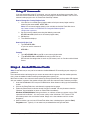
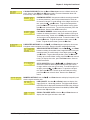
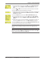
Figure 3-1. Front panel
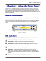
LED IndicatorsLED Indicators
LED IndicatorsLED Indicators
LED Indicators
The MT5600BA-V.92 has six LED indicators on the front panel that indicate status and activity:
Receive Data. The RD indicator flashes when the modem is receiving data.
Transmit Data. The TD indicator flashes when the modem is transmitting data.
Carrier Detect. The CD indicator lights when the modem detects a valid carrier signal from
another modem. It is on when the modem is communicating with the other modem, and off when
the link is broken.
Off-Hook. The OH indicator lights when the modem is off-hook, which occurs when the
modem is dialing, online, or answering a call. The LED flashes when the modem pulse-dials.
Terminal Ready. The TR indicator lights when a communication program is using the
modem. It means the modem is ready for an outgoing or incoming call. It goes off when the
communication program disconnects the serial port. When it goes off, a connected modem will
disconnect.
Test Mode. The TM indicator lights when the modem is in test mode.

Chapter 3 - Using the Front Panel
13
Multi-Tech Systems, Inc. MT5600BA/BL Series User Guide (S000276E)
Liquid CrLiquid Cr
Liquid CrLiquid Cr
Liquid Cr
yy
yy
y
stst
stst
st
al Dispal Disp
al Dispal Disp
al Disp
lala
lala
la
yy
yy
y
(L (L
(L (L
(L
CD)CD)
CD)CD)
CD)
The MultiModemII’s backlit liquid crystal display (LCD) has two functions: to display the current status of
the modem and to display configuration menus, which are selected using the four pushbuttons on the
front panel.
OptOpt
OptOpt
Opt
ii
ii
i
oo
oo
o
n Selen Sele
n Selen Sele
n Sele
ctct
ctct
ct
ii
ii
i
oo
oo
o
nn
nn
n
To select most configuration options, simply display the option in the LCD, and then press the Enter
button to select it. An OPTION SET message appears to confirm the selection. To exit the OPTION SET
message, press any button.
Some options, such as password options and phone number options, require you to enter a character
string. To select a character, press the
ÇÇ
ÇÇ
Ç
ÅÅ
ÅÅ
Å
and
ÈÈ
ÈÈ
È buttons. To go to the next character position, press
the
ÆÆ
ÆÆ
Æ button. To backspace, press the
ÆÆ
ÆÆ
Æ button before selecting a character. To exit without saving,
press the
ÆÆ
ÆÆ
Æ button several times. To save a character string, press the Enter button.
Menu StMenu St
Menu StMenu St
Menu St
rr
rr
r
uctuct
uctuct
uct
urur
urur
ur
ee
ee
e
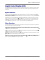
The LCD menus have a tree structure with multiple trunks, limbs, branches, and twigs. For a schematic
view, refer to the menu map on the next page.
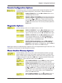
Trunks are the major divisions of the menu tree. There are seven trunks: Status, Basic Options, Ad-
vanced Options, Remote Configuration, Diagnostics, Phone Number Memory, and Caller ID. Use the
ÇÇ
ÇÇ
Ç
ÅÅ
ÅÅ
Å
and
ÈÈ
ÈÈ
È buttons to move between trunks.
Limbs are subdivisions of trunks. Use the
ÆÆ
ÆÆ
Æ button to move from a trunk onto its first limb, and the
ÇÇ
ÇÇ
Ç
ÅÅ
ÅÅ
Å
and
ÈÈ
ÈÈ
È buttons to move between limbs on the trunk.
Branches are subdivisions of limbs. Use the
ÆÆ
ÆÆ
Æ button to move from a limb onto its first branch, and the
ÇÇ
ÇÇ
Ç
ÅÅ
ÅÅ
Å
and
ÈÈ
ÈÈ
È buttons to move between branches on the limb.
Twigs are status screens and options that are accessible only from branches. Use the
ÆÆ
ÆÆ
Æ button to move
from a branch to its first status screen or option; then press the
ÇÇ
ÇÇ
Ç
ÅÅ
ÅÅ
Å
and
ÈÈ
ÈÈ
È buttons to move between
options, and press the Enter button to select an option.

Chapter 3 - Using the Front Panel
14
Multi-Tech Systems, Inc. MT5600BA/BL Series User Guide (S000276E)
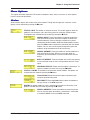
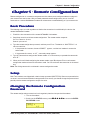
Menu OMenu O
Menu OMenu O
Menu O
vv
vv
v
erer
erer
er
vv
vv
v
ii
ii
i
ee
ee
e
ww
ww
w
Trunks Limbs Branches Twigs
Status =
, ,
,
,
,
Ent
,
,
Ent
,
,
Ent
,
,
Ent
,
,
Ent
,
,
Ent
,
,
Ent
,
,
Ent
,
,
Ent
,
,
Ent
,
,
Ent
,
,
Ent
,
,
,
,
,
, ,
,
,
, ,
,
,
,
,
,
,
,
,
,
,
,
,
,
,
,
,
,
,
,
,
,
,
,
,
,
,
,
,
,
,
,
,
,
Ent
,
Ent
,
,
Ent
,
,
,
,
,
Status =
Idle
Status =
Online
Basic Options
Manual Orig.?
Manual Answer?
Disconnect?49333,Async,Lapm
PSTN?
EC on? (&E2)
DTR normal?
(&D2)
CD forced on?
(&C0)
Enable RC?
Current Settings=
PSTN
Current Settings=
&E1
Current Settings=
&D2
Current Settings=
&C1 &C4
Current Settings=
Enabled
Line Type
Options
Error Correction
Options
DTR Options
Carrier Detect
Options
Enable / Disable
R,C,
Remote Config.
Password
Enter Password
A
Analog Loopback
Initiate AL?
Test in Progress
Initiate DL?
List Phone
Numbers
Enter Phone
Numbers
Enter Phone #0?
Enter Phone #1?
Phone #0?
Phone #1?
Terminate RDL?
Enable FCID?
(#CID1)
Region Setting
#CID0
Region Profile
B5
Region Profile
XX?
Current Setting =
02
Online Options
Dialing Options
Advanced Options
Remote
Config.
Caller I.D. Caller I.D.
Options
Phone Number
Mem. Ops.
Diagnostic
Options
Remote Config.
Password
Diagnostics
Diagnostic
Options
Phone Number
Memory
Phone Number
Mem. Ops.
Region Setting
Options
Region Select
,
( automatic selection )

Chapter 3 - Using the Front Panel
15
Multi-Tech Systems, Inc. MT5600BA/BL Series User Guide (S000276E)
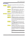
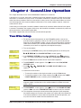
StSt
StSt
St
aa
aa
a
tt
tt
t
us us
us us
us
TrTr
TrTr
Tr
unkunk
unkunk
unk
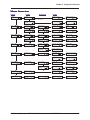
The Status Trunk shows the current operating status of the modem. Limb changes are automatic, but
certain options can be accessed by pressing the
ÆÆ
ÆÆ
Æ button. Note that when the modem is online, pressing
the
ÆÆ
ÆÆ
Æ button shows the connect status, including the data speed, connection type, and compression
type.
Limbs Twigs
If Idle
If
Online

Chapter 3 - Using the Front Panel
16
Multi-Tech Systems, Inc. MT5600BA/BL Series User Guide (S000276E)
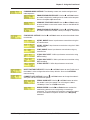
BB
BB
B
asiasi
asiasi
asi
c Optc Opt
c Optc Opt
c Opt
ii
ii
i
oo
oo
o
ns ns
ns ns
ns
TrTr
TrTr
Tr
unkunk
unkunk
unk
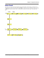
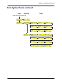
Use the Basic Options Trunk to configure the modem’s basic operating conditions. When entering a
number, use the
ÇÇ
ÇÇ
Ç
ÅÅ
ÅÅ
Å
and
ÈÈ
ÈÈ
È buttons to scroll through a list of digits and characters. To go to the next
position, press the
ÆÆ
ÆÆ
Æ button. To back up or to exit without dialing, press the
ÆÆ
ÆÆ
Æ button several times.
Limbs Branches Twigs
Continued on next page
Current Setting
Async AT
Async, SLAV?
Async, XCLK?

Chapter 3 - Using the Front Panel
17
Multi-Tech Systems, Inc. MT5600BA/BL Series User Guide (S000276E)
BB
BB
B
asiasi
asiasi
asi
c Optc Opt
c Optc Opt
c Opt
ii
ii
i
oo
oo
o
ns ns
ns ns
ns
TrTr
TrTr
Tr
unkunk
unkunk
unk
,,
,,
,
c c
c c
c
oo
oo
o
ntnt
ntnt
nt
inuedinued
inuedinued
inued
Continued from previous page
Limbs Branches Twigs

Chapter 3 - Using the Front Panel
18
Multi-Tech Systems, Inc. MT5600BA/BL Series User Guide (S000276E)
AA
AA
A
dvdv
dvdv
dv
ancanc
ancanc
anc
ed Opted Opt
ed Opted Opt
ed Opt
ii
ii
i
oo
oo
o
ns ns
ns ns
ns
TrTr
TrTr
Tr
unkunk
unkunk
unk
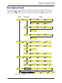
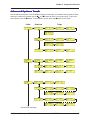
Use the Advanced Options Trunk to configure RS-232, dial backup, and callback security options. When
entering a number or password, use the
ÇÇ
ÇÇ
Ç
ÅÅ
ÅÅ
Å
and
ÈÈ
ÈÈ
È buttons to select a character or digit. To go to the
next position, press the
ÆÆ
ÆÆ
Æ button. To backspace or to exit, press the
ÆÆ
ÆÆ
Æ button several times.
Limbs Branches Twigs
Continued on next page

Chapter 3 - Using the Front Panel
19
Multi-Tech Systems, Inc. MT5600BA/BL Series User Guide (S000276E)
AA
AA
A
dvdv
dvdv
dv
ancanc
ancanc
anc
ed Opted Opt
ed Opted Opt
ed Opt
ii
ii
i
oo
oo
o
ns ns
ns ns
ns
TrTr
TrTr
Tr
unkunk
unkunk
unk
,,
,,
,
c c
c c
c
oo
oo
o
ntnt
ntnt
nt
inuedinued
inuedinued
inued
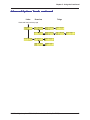
Continued from previous page
Limbs Branches Twigs

Chapter 3 - Using the Front Panel
20
Multi-Tech Systems, Inc. MT5600BA/BL Series User Guide (S000276E)
RR
RR
R
emote Cemote C
emote Cemote C
emote C
oo
oo
o
nfnf
nfnf
nf
igig
igig
ig
urur
urur
ur
aa
aa
a
tt
tt
t
ii
ii
i
oo
oo
o
n Optn Opt
n Optn Opt
n Opt
ii
ii
i
oo
oo
o
ns ns
ns ns
ns
TrTr
TrTr
Tr
unkunk
unkunk
unk
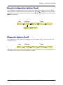
Use the Remote Configuration Options Trunk to enable or disable remote configuration on the modem,
and to change the password. When entering the password, use the
ÇÇ
ÇÇ
Ç
ÅÅ
ÅÅ
Å
and
ÈÈ
ÈÈ
È buttons to scroll through
the alphabet. To go to the next character position, press the
ÆÆ
ÆÆ
Æ button. To backspace or to exit, press the
ÆÆ
ÆÆ
Æ button several times.
Limb Branches Twigs
DiagDiag
DiagDiag
Diag
nono
nono
no
stst
stst
st
ii
ii
i
c Optc Opt
c Optc Opt
c Opt
ii
ii
i
oo
oo
o
ns ns
ns ns
ns
TrTr
TrTr
Tr
unkunk
unkunk
unk
Use the Diagnostic Options Trunk to run loopback tests on the modem. When a test is in progress, the
TM indicator lights.
Limb Branches Twigs
Note: Digital Loopback and Remote Digital Loopback tests must be performed using AT Commands. The
LCD option to run these tests has been temporarily removed.
La pagina si sta caricando...
La pagina si sta caricando...
La pagina si sta caricando...
La pagina si sta caricando...
La pagina si sta caricando...
La pagina si sta caricando...
La pagina si sta caricando...
La pagina si sta caricando...
La pagina si sta caricando...
La pagina si sta caricando...
La pagina si sta caricando...
La pagina si sta caricando...
La pagina si sta caricando...
La pagina si sta caricando...
La pagina si sta caricando...
La pagina si sta caricando...
La pagina si sta caricando...
La pagina si sta caricando...
La pagina si sta caricando...
La pagina si sta caricando...
La pagina si sta caricando...
La pagina si sta caricando...
La pagina si sta caricando...
La pagina si sta caricando...
La pagina si sta caricando...
La pagina si sta caricando...
La pagina si sta caricando...
La pagina si sta caricando...
La pagina si sta caricando...
La pagina si sta caricando...
La pagina si sta caricando...
La pagina si sta caricando...
La pagina si sta caricando...
La pagina si sta caricando...
La pagina si sta caricando...
La pagina si sta caricando...
La pagina si sta caricando...
La pagina si sta caricando...
La pagina si sta caricando...
La pagina si sta caricando...
La pagina si sta caricando...
La pagina si sta caricando...
-
 1
1
-
 2
2
-
 3
3
-
 4
4
-
 5
5
-
 6
6
-
 7
7
-
 8
8
-
 9
9
-
 10
10
-
 11
11
-
 12
12
-
 13
13
-
 14
14
-
 15
15
-
 16
16
-
 17
17
-
 18
18
-
 19
19
-
 20
20
-
 21
21
-
 22
22
-
 23
23
-
 24
24
-
 25
25
-
 26
26
-
 27
27
-
 28
28
-
 29
29
-
 30
30
-
 31
31
-
 32
32
-
 33
33
-
 34
34
-
 35
35
-
 36
36
-
 37
37
-
 38
38
-
 39
39
-
 40
40
-
 41
41
-
 42
42
-
 43
43
-
 44
44
-
 45
45
-
 46
46
-
 47
47
-
 48
48
-
 49
49
-
 50
50
-
 51
51
-
 52
52
-
 53
53
-
 54
54
-
 55
55
-
 56
56
-
 57
57
-
 58
58
-
 59
59
-
 60
60
-
 61
61
-
 62
62


in altre lingue
- English: Multi-Tech MT5600BA–V.92 User manual
Altri documenti
-
 Paradyne 6035 Guida d'installazione
-
3com 56K INTERNAL VOICE FAXMODEM - QUICK FOR WINDOWS REV 1.2 Manuale utente
-
Promise Technology NS4300N Manuale utente
-
US Robotics USR205630D Manuale del proprietario
-
Conceptronic C56U Manuale utente
-
Compaq Presario 2500 - Notebook PC Manuale utente
-
-
ZyXEL WAH3004 Manuale utente
-
-
