SOUNDIGITAL 600.4 EVO5 Manuale del proprietario
- Categoria
- Attrezzatura musicale
- Tipo
- Manuale del proprietario

OWNER´S MANUAL
600.4

3
3
4
5
6
7
8
8
9
10
10
11
12
13
Code document review: 1000750321-001/AUG2022
Introdução..............................................................................................................................
Conteúdo da embalagem............................................................................................
Instruções de segurança..............................................................................................
Montagem e desmontagem da capa plástica.................................................
Descrição dos painéis
Entradas de áudio e controles........................................................
Alimentação e saídas de áudio........................................................
Dimensionamento elétrico...........................................................................................
Entradas de áudio.............................................................................................................
Sequência de instalação...............................................................................................
Diagrama de conexões
Configuração em quatro canais..................................................
Configuração em três canais........................................................
Configuração em dois canais.......................................................
Procedimento para regulagem do ganho........................................................
..........................................................................................Regulagem do Crossover
Especificações Técnicas
Parâmetros............................................................................................
Dados Dimensionais........................................................................
11
13
Introduction........................................................................................................................... 3
Package contents ............................................................................................................ 3
Safety instructions ............................................................................................................ 4
Assembling and Disassembling the plastic cover........................................ 5
Panels description
Audio inputs and controls .................................................................. 6
Power inputs and audio outputs..................................................... 7
Electrical Dimensioning................................................................................................. 8
Audio inputs ......................................................................................................................... 8
Installation sequence...................................................................................................... 9
Wiring diagram
Four channels wiring diagram......................................................... 10
Three channels wiring diagram ...................................................... 10
Two channels wiring diagram .......................................................... 11
Gain adjustment procedure........................................................................................ 11
Crossovers set up............................................................................................................ 12
Technical specifications
Parameters ................................................................................................. 13
Dimensional data..................................................................................... 13
TABLE OF CONTENTS

INTRODUÇÃOINTRODUÇÃO
Prezado Consumidor,
Parabéns por ter adquirido um produto da mais alta qualidade e tecnologia!
Os produtos da SounDigital são desenvolvidos para garantir a máxima eficiência e
confiabilidade em seu sistema de áudio.
Amplificadores Classe D:
Os amplificadores Classe D têm como principais características a qualidade de
áudio, eficiência, versatilidade de aplicação e design compacto. Seguem as
vantagens dessas características:
Qualidade de Áudio – No passado, os produtos Classe D tinham resposta
limitada e para frequências mais altas, os produtos Classe AB tinham melhor
desempenho, porém a eficiência destes eram muito baixas. As novas tecnologias
introduzidas pela SounDigital resultaram em um amplificador Classe D com alta
eficiência e desempenho superior ao Classe AB.
Eficiência – Os amplificadores SounDigital Classe D tem eficiência total (Saída +
Fonte) superior a 70% o que garante um menor consumo de bateria e menor
aquecimento.
Versatilidade de Aplicação – A resposta plana em todas as frequências dos
amplificadores SounDigital permite que estes sejam utilizados em todos os
sistemas de som automotivo. Atendendo as exigências com extrema qualidade.
Design Compacto – A alta eficiência e alta tecnologia aplicada, permite que os
amplificadores SounDigital sejam muito compactos, facilitando a instalação em
veículos onde o espaço é limitado.
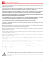
INFORMAÇÕES IMPORTANTES
Leia atentamente este manual e siga de forma precisa todas as informações
aqui contidas, estas são muito importantes e permitem que seu amplificador funcione
de forma ideal. Caso julgue necessário, não hesite em contatar nosso suporte técnico
pelo e-mail sac@soundigital.com ou pelo SAC (51) 3042-9001.
CONTEÚDO DA EMBALAGEM
▪ 01 Amplificador 600.4 EVO5
▪ 01 Guia rápido de instalação com certificado de garantia
▪ 01 Adesivo promocional
3
INTRODUCTION
3
DEAR CUSTOMER,
CONGRATULATIONS ON ACQUIRING A PRODUCT WITH THE HIGHEST
QUALITY AND TECHNOLOGY!
You have just purchased a SounDigital product of the highest technology and
quality, so we thank you for your confidence.
Class D Amplifiers:
Class D amplifiers have as main characteristics the audio quality, efficiency,
application versatility and compact design. Following are the advantages of these
features:
Audio Quality – In the past, Class D products had limited response and for higher
frequencies, Class AB products performed better, but their efficiency was very low.
The new technologies introduced by SounDigital resulted in a Class D amplifier
with high efficiency and superior Class AB performance.
Efficiency – SounDigital Class D amplifiers have total efficiency (output + power
source) greater than 70%, which guarantees lower battery consumption and less
heating.
Application Versatility – The flat full-frequency response of SounDigital
amplifiers allows them to be used in all car sound systems. Meeting the demands
with extreme quality.
Compact Design – The high efficiency and high technology applied, allows
SounDigital amplifiers to be very compact, facilitating installation in vehicles where
space is limited.
IMPORTANT INFORMATIONS
On this manual you will learn about the product, its features and characteristics, in
order to obtain the best result and to be able to enjoy your music with SounDigital
quality and power.
To better understand and take advantage of all the functions of the product and use
it safely, read this manual carefully and if you have any questions, consult our
support by email [email protected].
PACKAGE CONTENTS
▪ 01 600.4 EVO5 Amplifier
▪ 01 Installation quick guide with warranty card
▪ 01 Promotional sticker

INSTRUÇÕES DE SEGURANÇA
Para prevenir ferimentos ao usuário ou danos ao amplificador, leia todas as
instruções de segurança contidas neste manual;
Caso sinta-se inseguro para fazer a instalação do equipamento, procure o suporte
técnico SounDigital ou um profissional qualificado em instalação de som
automotivo;
Antes de proceder com a instalação de qualquer equipamento elétrico no veículo,
desligue o terminal negativo (-) da bateria para evitar princípios de incêndio,
ferimentos ou danos ao amplificador;
Utilize seu sistema de som com segurança, a exposição contínua a pressões
sonoras acima de 85 decibéis pode causar danos auditivos irreversíveis;
Este equipamento é para uso em baterias automotivas de tensão DC entre 12,6 e
14,4 volts. Antes de instalar o equipamento, verifique a tensão das baterias;
Não instale o amplificador no compartimento do motor ou em locais expostos a
água, umidade, pó ou sujeira;
Instale o amplificador em um local arejado e evite que as janelas laterais de
ventilação sejam obstruídas;
Fixe o amplificador de maneira apropriada e firme. Evite a fixação em partes
metálicas, pois este procedimento pode causar "Looping" de terra (ruídos);
Utilize O-rings de borracha ao passar os fios em paredes metálicas a fim de evitar " "
que os mesmos sejam cortados e provoquem curto-circuito;
Certifique-se de que o local escolhido para instalação do amplificador não
prejudique o funcionamento do veículo;
Durante a utilização deste produto, a carcaça/dissipador em alumínio pode
alcançar temperaturas superiores a 60°C. Antes de tocar no amplificador, tenha
certeza que este está frio;
Para manter a dissipação térmica eficiente, limpe periodicamente o dissipador,
retirando pó e impurezas, com a ajuda de um pincel e/ou pano seco;
Muito cuidado ao fazer furos no veículo, certifique-se de não furar o tanque de
combustível, linhas de freio, cabos elétricos, etc;
Certifique-se que todos os cabos estão corretamente fixados ao longo de toda a
instalação;
Utilize luvas, óculos de proteção e todos os equipamentos de segurança
necessários durante a instalação dos amplificadores SounDigital.
Este símbolo alerta o usuário sobre a presença de instruções importantes.
Deixar de cumprir estas instruções pode vir a causar dano ao amplificador
ou ao usuário.
Cuidado!
#
SAFETY INSTRUCTIONS
THIS "WARNING" SIGN ALERTS THE USER OF IMPORTANT INFO. NOT FOLLOWING
THIS INSTRUCTIONS MAY CAUSE INJURIES TO THE USER OR DAMAGE TO THE
EQUIPMENT.
Warning!
To prevent injuries to the user or damage to the amplifier, read all safety instructions
written on this manual;
If you are insecure about the installation of this equipment, get in touch with our
tech support or with a professional specialized in car audio installation;
Before proceeding with the installation of any electric equipment on your vehicle,
unplug the negative (-) terminal of the battery to avoid fires, injuries or damages;
Use your sound system safely. The continuous exposure to sound pressures over
85dB may cause irreversible hearing damage;
This equipment is for use in automotive DC voltage batteries between 12.6 and
14.4 volts. Before installing the equipment, check voltage of the batteries;
Do not install the amplifier in places exposed to water, dirt or humidity;
Choose a ventilated place to install the amplifier and avoid blocking the side
ventilation windows;
Mount the amplifier in a secure way. Avoid mounting it on metallic parts of the
vehicle, because it may cause ground looping (noise);
Make sure that the location chosen for the amplifier installation does not effect the
operation of the vehicle;
When passing cables through metallic walls, use rubber O-rings to avoid cable
cutting and short-circuits;
Clean the amplifier periodically with brush or dry cloth to assure the thermal
efficiency of the heatsink;
This product may reach temperatures over 60°C/140°F. Make sure it is cold before
touching it;
Be careful when making holes in the vehicle. Make sure you are not making holes
in the fuel tank, brake lines or electrical cables of the vehicle;
Make sure the cables are properly secured throughout the installation;
Wear gloves, safety glasses and and all necessary PPE during the installation of
SounDigital amplifiers.
4

1 2
21
A
B
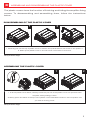
DISASSEMBLING OF THE PLASTIC COVER
ASSEMBLING THE PLASTIC COVER
The plastic covers have the function of finishing and hiding the amplifier fixing
screws. To disassembling and assembling them, follow the instructions
below.
1. Carefully pull out the top of plastic cover to release the upside latches, as shown in the picture 1.
2. Slide up the plastic cover in a continuous movement to remove it.
1. To fit the plastic cover back, carefully insert the point A of the plastic cover into point B of the
amplifier, slowly sliding it down.
2. Gently press the sides of the top of the plastic cover towards the bottom of the amplifier until
you hear a clicking noise.
EN
ASSEMBLING AND DISASSEMBLING THE PLASTIC COVER
5
*Merely illustrative images.
*Merely illustrative images.

1
5 8
6 7 2
4
3
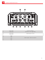
Variable Gain Control
Audio inputs - RCA connectors
CH1/CH2
CH3/CH4
CH1/CH2
CH3/CH4
6
8
5
7
4
3
2
1
CH1
CH4
CH2
CH3
6
PANELS DESCRIPTION
Crossover Switch
Low Pass - Full - High Pass

"Power ON" LED indicator (Blue)
Negative speaker connector (-)
Positive speaker connector (+)
Negative power supply connector (GND)
Remote power supply connector (REM)
Positive power supply connector (+12VDC)
910 11 12 13 14 15 16 17 18 19 20
14
13
12
11
10
9
15
16
17
18
19
20
CH4
-
-
-
-
CH4
CH3
CH3
CH2
CH2
CH1
CH1
7
Positive speaker connector (+)
Negative speaker connector (-)
Positive speaker connector (+)
Positive speaker connector (+)
Negative speaker connector (-)
Negative speaker connector (-)
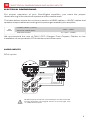
PANELS DESCRIPTION

AUDIO INPUTS
RCA inputs
POWER CABLE (+12VDC)
GROUND CABLE (GND)
SPEAKER CABLE
600
WRMS
10mm² - 7 AWG
8
2 x 1.5mm² - 15 AWG
All RCA Inputs must be connected for the all channels
to work properly. If the signal source is mono type, use
"Y" cable at the input.
For proper operation of your SounDigital amplifier, you need the proper
dimensioning of the electrical system and the cables used.
The table below shows the minimum section of GND cables, +12VDC cables and
speaker output cables according to the power generated by the amplifier.
ELECTRICAL DIMENSIONING AND AUDIO INPUTS
ELECTRICAL DIMENSIONING
We recommend the use of ONLY OFC (Oxygen Free Copper) Cables on the
installation of our products. CCA cables must not be used.

ØMount the amplifier in such a way you have access to the connectors;
ØInstall the power cables in the vehicle properly, starting from the battery to the fuse
holder or circuit breaker, use the cable with the appropriate size. Make all
connections, install fuse holders or circuit breakers, but without placing the fuses
or with the circuit breakers in the "OFF" position;
ØConnect the power cables in to the amplifier, observing the polarity. Connect all the
positive cables from the fuse holder or circuit breaker to the positive conector of
the amplifier and all the negative power cables from the batteries to the negative
connector of the amplifier;
ØThe ground cable must be as short as possible and must be connected to the
vehicle chassis and the battery negative;
ØInstall the signal input cables in a proper way, distant from the power cables;
ØConnect the RCA or the high level signal input cables to the head unit and
amplifiers;
ØInstall the audio output cables with the appropriate section, distant from the power
and audio input cables;
ØConnect the audio output cables to the amplifier and speakers respecting the
positive (+) and negative (-) polarities;
ØInstall the remote cable with the power cables, using 1.5mm² (15 AWG) cable or
thicker;
ØConnect the remote power cable to the amplifier's "REM" terminal at the main unit's
remote power output (when not using the high level signal inputs);
ØBefore powering the system, verify all the connections and make sure there are no
mistakes or short-circuits on the power and ground cables;
Ø;Reconnect the ground of the batteries
ØCheck if the head unit is turned off and then place the fuses in the fuse holders or
switch the circuit breakers on;
ØTurn on the main unit and the amplifier will turn on the "ON" LED indicating that it is
in operation.
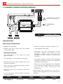
INSTALLATION SEQUENCE
Warning!
Warning!
Remove the paint between
the terminal and chassis
9
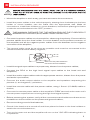
THE MAXIMUM DISTANCE FOR THE INSTALLATION OF THE FUSE/CIRCUIT
BREAKER IS 12 INCHES (30cm) AWAY FROM THE BATTERY.

FUSE
FUSE
REMOTE
FUSE
FUSE
REMOTE
10
È
See "AUDIO INPUTS”
on page 8
All RCA Inputs must be connected for
the all channels to work properly.
WIRING DIAGRAM
4 CHANNELS WIRING DIAGRAM
È
See "AUDIO INPUTS”
on page 8
All RCA Inputs must be connected for
the all channels to work properly.
3 CHANNELS WIRING DIAGRAM
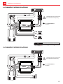
Model
Minimum impedance of use according to the model
4Ω
Bridge
2Ω
Per channel
600.4 4Ω
(PER CHANNEL)
(PER CHANNEL)
(PER CHANNEL)
(BRIDGE)

GAIN SETTING
Necessary equipament:
ØDigital AC voltmeter;
ØMedia with sine wave test tone 60Hz
recorded at 0db;
ØSet up procedure
This procedure is the same for both
Ø
gain controls;
ØTurn the gain control all the way down;
ØDisconnect the output cables from the
amplifier outputs;
ØTurn off all processing (bass, treble,
loudness, EQ, etc.);
ØSet the source unit volume to 3/4 of full
volume;
ØOn the CD player, set the fader control to
center position;
ØSet the crossover selector switch in "F";
Ø Use a 60Hz sine wave;
ØConnect the AC voltmeter to the
speaker output connectors of the
amplifier. Make sure you test the
voltage at the correct connectors
(+ and –);
ØIncrease the gain control until the target
voltage is observed with the voltmeter
(see the chart below);
ØOnce you have adjusted the amplifier
to its correct voltage output, turn off the
s o u r c e u n i t a n d r e c o n n e c t t h e
speaker(s).
Download the tracks for set up in
https://soundigitalusa.com/tracks-for-
set-up/
Model
Minimum impedance of use according to the model
4Ω
Bridge
2Ω
Per channel
600.4 4Ω
FUSE
FUSE
REMOTE
MODEL BRIDGE /
POWER
STEREO /
POWER
STEREO OUTPUT
VOLTAGE
BRIDGE OUTPUT
VOLTAGE
4Ω/ 2x300W2 / 4x150WΩ17,32V 34,64V
600.4 4Ω
WIRING DIAGRAM / GAIN SETTING
2 CHANNELS WIRING DIAGRAM (BRIDGE)
È
See "AUDIO INPUTS”
on page 8
All RCA Inputs must be connected for
the all channels to work properly.
11
(BRIDGE)

ØSelecione a chave na posição "F" - u Todas as freq ências serão reproduzidas
conforme a "Figura 1";
ØSelecione a chave na posição "HP" - Todas as frequências acima de 80Hz serão
reproduzidas como na "Figura 2";
ØSelecione a chave na posição "LP" - Todas as frequências abaixo de 80Hz serão
reproduzidas como na "Figura 3";
"F" Todas as freqüências serão reproduzidas;
"LP " Frequências abaixo de 80Hz serão reproduzidas
"HP " Frequências acima de 80Hz serão reproduzidas
12
-3dB
c/2
ƒ
High
Pass
c
ƒ
High
Pass
A
0dB
-12dB
dB
Hz
-3dB
0dB
-12dB
Low
Pass
B
c
ƒc*2
ƒ
Low
Pass
dB
Hz
0dB
-3dB
5Hz 22kHz
dB
Hz
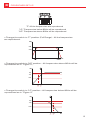
CROSSOVER SET UP
Ø Change the switch to "F" position (Full Range): All the frequencies
are reproduced.
Ø Change the switch to "HP" position - All frequencies above 80Hz will be
reproduced as in "Figure 2";
"F" All the frequencies are reproduced
"LP " Frequencies below 80Hz will be reproduced
"HP " Frequencies above 80Hz will be reproduced
0dB
-3dB
5Hz 22kHz
dB
Hz
-3dB
c/2
ƒ
High
Pass
c
ƒ
High
Pass
A
0dB
-12dB
dB
Hz
Ø Change the switch to "LP" position - All frequencies below 80Hz will be
reproduced as in "Figure 3".
-3dB
0dB
-12dB
Low
Pass
B
c
ƒc*2
ƒ
Low
Pass
dB
Hz

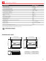
Operating Voltage
SNR
Input Sensitivity (RCA)
Current Draw (music)
Current Draw (max.)
Total Efficiency
Damping Factor (@100Hz nominal impedance)
Power Cable
Fuse* (music)
Recommended battery (minimum)
Low Pass filter (12dB/oct)
2 x 1.5 mm² (15 AWG)
Power RMS (Bridge) @ 8Ω** 2 x 198W
Power RMS (Bridge) @ 4Ω** 2 x 300W
Power RMS @ 4Ω** 4 x 100W
Frequency Response (-3dB) 10Hz ~ 20kHz
8V ~ 16V
88dB
0.2V ~ 2V
27A
54A
88%
200
10mm² (7 AWG)
35A
35Ah
80Hz
Speaker Cable
50,9mm (2.0")
4Ω
600.4
Power RMS @ 2Ω** 4 x 150W
High Pass filter (12dB/oct) 80Hz
101,0mm (4.0")
121,3mm (4.8")
113,0mm (4.4")
135,4mm (5.3")
13
TECHNICAL SPECS
PARAMETERS
DIMENSIONAL DATA
0,66 kg (1.46 lb)
0,73 kg (1.65 lb)
Net Weight
Gross Weight
**Power at 12.6V @ 60Hz with a maximum THD of 1%.
*It is mandatory to install the fuse at a maximum distance of 12 inches from the battery.
**POWER RATING ACCORDING TO
CTA-2006 INDUSTRY STANDARDS

CODE.: 1000750321-001/AUG2022
-
 1
1
-
 2
2
-
 3
3
-
 4
4
-
 5
5
-
 6
6
-
 7
7
-
 8
8
-
 9
9
-
 10
10
-
 11
11
-
 12
12
-
 13
13
-
 14
14


SOUNDIGITAL 600.4 EVO5 Manuale del proprietario
- Categoria
- Attrezzatura musicale
- Tipo
- Manuale del proprietario
in altre lingue
Documenti correlati
Altri documenti
-
 Rockford Fosgate Prime R600-5 Guida utente
-
Audio Design LA-4100 Manuale del proprietario
-
Audio Design GTi4100 Manuale utente
-
 Lightning Audio LA-8004 Manuale utente
-
Yamaha S12 Manuale del proprietario
-
Carvin Audio LT5204 Manuale utente
-
StetSom BRAVO HQ800.4 Manuale del proprietario
-
Hifonics NXI4404 Manuale utente
-
HELVIA ZEUS X Series Manuale utente

