Carvin Audio LT5204 Manuale utente
- Categoria
- Set di altoparlanti
- Tipo
- Manuale utente

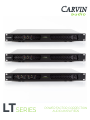
LT SERIES
POER FACTOR CORRECTION
AUDIO AMPLIFIERS

CARVIN ENGINEERING DATA CARVIN ENGINEERING DATALT Amplier Series
PG 2
WARRANTY
This CARVIN product is guaranteed to be free from electrical and mechanical defects for a period of one year from date
of purchase. Retain proof of purchase. This warranty is in lieu of any and all other guarantees or warranties expressed or
implied. There shall be no recovery for any consequential or incidental damages.
INTRODUCTION
Carvin introduces three lightweight power amp models
which provide pure amplification of the original source to
extreme levels, covering all frequencies without added
ohms capable, and include PFC Power Factor Correction,
which is internationally recognized as the foremost
self-regulating power supply for high-end amplifiers.
Each power amp model has exceptional headroom with
lower power requirements than amps with a traditional
power supply.
LT MODELS
»
»
RMS
»
PFC POWER FACTOR CORRECTION
Our experience results in advanced features like soft
starting PFC Power Factor Correction, which corrects the
incoming AC by synchronizing the AC voltage to the line
current to reduce energy consumption and heat while
producing substantially more power from the same AC
input. Crystal clear transparency is provided by CLASS
D output stages featuring linear circuits with a near
theoretical zero distortion level. Fast slew rate 50V/µS
circuits produce power at extreme levels delivering audio
in its purest state with no added color.
ENGINEERING EXCELLENCE
doubling rack amp capacities. Large output FETs deliver
are easily facilitated. Fail-safe features include variable speed
cooling that draws cold air from the front while venting to
the rear. All power ratings are for ambient temperatures up
accommodated including unregulated generators. Custom
LT SERIES FEATURES
»Active PFC Power Factor Correction
»
»
»Natural, pure-state amplification
»
»
»
»
»
»Front to rear cooling system
»
»
»
ohms
»
ohms
exceptional headroom for distortion-free performances.
»
professional amplifiers offer technological advancements
beyond the common power amp, providing the purest
audio at the highest levels.

CARVIN ENGINEERING DATALT Amplier Series
PG 3
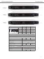
LT Amplier Series
Model
Ω/Stereo
Ω/Stereo
Ω/Stereo
Ω/Bridge
Ω/Bridge
Vrms Bridge Mode
V/µS
Ω .97vrms(+2dBu) 1.2vrms(+4dBu) 1.95vrms(+8dBu) 3vrms(+12dBu)
...
Ω).
Input Impedance Ω Balanced, 10kΩ Unbalanced
Damping Factor ≥
Signal to Noise Ratio ≥ ≥ ≥
AC Input
Ambient Temperature Range FF
Dimensions ..
Net Weight
LT2000
LT5800
LT5204
CH4
CH4
CH3
CH3
CH1
CH1
CH2
CH2
CH3
+
-
2-
1-
2+
1+
CH3
+
-
CH4
+
-
2-
1-
2+
1+
CH4
+
-
CH1
+
-
2-
1-
2+
1+
CH1
+
-
CH2
+
-
2-
1-
2+
1+
CH2
+
-
PFC Professional Series
BRIDGE CH + = POS = NEG
BRIDGE CH + = POS = NEG
0dB
-3dB
-6dB
-10dB
INPUT SENSITIVITY
MONO/BRDG
LIMITER OFF
CH4/HF
CH4/HF
CH3/ LF
CH3 CH1
CH3/LF
CH2/HF
CH1/LF
CH1/LF
CH2/HF
CH1/LFCH2/HF
+
-
CH4
2-
1-
2+
1+
+
-CH3
+
-
CH3 CH1
+
-
CH2
2-
1-
2+
1+
+
-CH1
+
-
PFC Professional Series
OHM W/CH - 153W x CH BRIDGE
4 OHM 78W/CH - 2575W x CH BRIDGE
2 OHM 1290W/CH
BRIDGE CH + = POS = NEG
BRIDGE CH + = POS = NEG
0dB
-3dB
-6dB
-10dB
INPUT SENSITIVITY
MONO/BRDG
LIMITER OFF
CH2/HF
CH1/ LF
CH1
CH2
CH2
CH1
CH1
CH2
+
-
2-
1-
2+
1+
CH2
+
-
CH1
+
-
2-
1-
2+
1+
CH1
+
-
CH1
+
-
CH2
2-
1-
2+
1+
+
-CH1
+
-
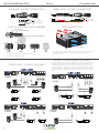
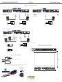
4-CONDUCTOR BI-AMP MODESTEREO MODE
ASSEMBLED IN PRC
- VAC -Hz
ASSEMBLED IN PRC
- VAC -Hz
OHM 4W/CH - W x CH BRIDGE
OHM W/CH - W x CH BRIDGE
OHM W/CH
PFC Professional Series
BRIDGE CH + = POS = NEG
0dB
-3dB
-6dB
-10dB
INPUT SENSITIVITY
MONO/BRDG
LIMITER OFF
ASSEMBLED IN PRC
- VAC -Hz
OHM W/CH - W x CH BRIDGE
4 OHM W/CH - W x CH BRIDGE
2 OHM W/CH
PFC Professional Series
BRIDGE CH + = POS = NEG
0dB
-3dB
-6dB
-10dB
INPUT SENSITIVITY
MONO/BRDG
LIMITER OFF
ASSEMBLED IN PRC
- VAC -Hz
OHM W/CH - W x CH BRIDGE
4 OHM W/CH - W x CH BRIDGE
2 OHM W/CH

CARVIN ENGINEERING DATA CARVIN ENGINEERING DATALT Amplier Series
PG 4
Set Up
carvinaudio.com
BALANCED
PIN 1 GND
PIN 3 - SIGNAL (BAL)
PIN 2 + SIGNAL (BAL)
UNBALANCED
PIN 1 GND
PIN 3 - SIGNAL (BAL)
PIN 2 + SIGNAL (BAL)
TIP
TIP
SLEEVE
SLEEVE
AIR FLOW DIRECTION
AQ2450
PFC Professional Series
PFC Professional Series
PFC Professional Series
PFC Professional Series
»For proper cooling make sure front panel has access to cool air and the
wall or obstruction.
Twist-Lok
Housing
Contact
Insert
Cable
Clamp
Securing
Hub
• Connection Configuration:
(1+) / positive (CH1 +)
(1-) / negative (CH1 -)
(2+) / positive (CH2 +)
(2-) / negative (CH2 -)
• Do not tin or solder wires.
• Slip "Securing Hub" then "Cable Clamp" over cable before attaching wires.
1+
1-
2+
2-
Solder tinned wires 1/4"
Strip cable insulation back 3/4"
»Actual color of individual wire conductors may vary
depending on cable manufacturer.
CH4
CH4
CH3
CH3
CH1
CH1
CH2
CH2
CH3
+
-
2-
1-
2+
1+
CH3
+
-
CH4
+
-
2-
1-
2+
1+
CH4
+
-
CH1
+
-
2-
1-
2+
1+
CH1
+
-
CH2
+
-
2-
1-
2+
1+
CH2
+
-
PFC Professional Series
BRIDGE CH + = POS = NEG
BRIDGE CH + = POS = NEG
0dB
-3dB
-6dB
-10dB
INPUT SENSITIVITY
MONO/BRDG
LIMITER OFF
CH4/HF
CH4/HF
CH3/ LF
CH3 CH1
CH3/LF
CH2/HF
CH1/LF
CH1/LF
CH2/HF
CH1/LFCH2/HF
+
-
CH4
2-
1-
2+
1+
+
-CH3
+
-
CH3 CH1
+
-
CH2
2-
1-
2+
1+
+
-CH1
+
-
PFC Professional Series
OHM W/CH - 153W x CH BRIDGE
4 OHM 78W/CH - 2575W x CH BRIDGE
2 OHM 1290W/CH
BRIDGE CH + = POS = NEG
BRIDGE CH + = POS = NEG
0dB
-3dB
-6dB
-10dB
INPUT SENSITIVITY
MONO/BRDG
LIMITER OFF
CH2/HF
CH1/ LF
CH1
CH2
CH2
CH1
CH1
CH2
+
-
2-
1-
2+
1+
CH2
+
-
CH1
+
-
2-
1-
2+
1+
CH1
+
-
CH1
+
-
CH2
2-
1-
2+
1+
+
-CH1
+
-
4-CONDUCTOR BI-AMP MODESTEREO MODE
ASSEMBLED IN PRC
- VAC -Hz
ASSEMBLED IN PRC
- VAC -Hz
OHM 4W/CH - W x CH BRIDGE
OHM W/CH - W x CH BRIDGE
OHM W/CH
PFC Professional Series
BRIDGE CH + = POS = NEG
0dB
-3dB
-6dB
-10dB
INPUT SENSITIVITY
MONO/BRDG
LIMITER OFF
ASSEMBLED IN PRC
- VAC -Hz
OHM W/CH - W x CH BRIDGE
4 OHM W/CH - W x CH BRIDGE
2 OHM W/CH
PFC Professional Series
BRIDGE CH + = POS = NEG
0dB
-3dB
-6dB
-10dB
INPUT SENSITIVITY
MONO/BRDG
LIMITER OFF
ASSEMBLED IN PRC
- VAC -Hz
OHM W/CH - W x CH BRIDGE
4 OHM W/CH - W x CH BRIDGE
2 OHM W/CH
»
cable. An electronic crossover must be connected between the mixer and
that can then be connected to the correct channel inputs on the power
amp.
LT2000LT2000 LT5800LT5800
LT5204
LT5204
FRONT

CARVIN ENGINEERING DATALT Amplier Series
PG 5
LT Amplier SeriesSet Up
carvinaudio.com
CH3
CH3 CH1
CH3
CH1
CH1
CH3
4 OHM
MIN
2-
1-
2+
1+
+
-
CH3
CH1
4 OHM
MIN
2-
1-
2+
1+
+
-
CH1
PFC Professional Series
BRIDGE CH + = POS = NEG
BRIDGE CH + = POS = NEG
0dB
-3dB
-6dB
-10dB
INPUT SENSITIVITY
MONO/BRDG
LIMITER OFF
CH 3 & 4CH 1 & 2
MONO BRIDGE MODE
MONO BRIDGE MODE
PFC Professional Series
OHM W/CH - W x CH BRIDGE
4 OHM W/CH - W x CH BRIDGE
2 OHM W/CH
BRIDGE CH + = POS = NEG
0dB
-3dB
-6dB
-10dB
INPUT SENSITIVITY
MONO/BRDG
LIMITER OFF
CH1
CH1
CH1
CH1
4 OHM
MIN
2-
1-
2+
1+
+
-
CH1
CH1
CH3
CH1
CH1
CH1
4 OHM
MIN
2-
1-
2+
1+
+
-
CH1
PFC Professional Series
BRIDGE CH + = POS = NEG
BRIDGE CH + = POS = NEG
0dB
-3dB
-6dB
-10dB
INPUT SENSITIVITY
MONO/BRDG
LIMITER OFF
CH 3 & 4CH 1 & 2
CH4
CH3
CH3
2-
1-
2+
1+
CH3
+
-
CH4
2-
1-
2+
1+
CH4
+
-
CH4
3 CHANNEL
MONO BRIDGE
SUBWOOFER
STEREO/2WAY
ASSEMBLED IN PRC
- VAC -Hz
ASSEMBLED IN PRC
- VAC -Hz
ASSEMBLED IN PRC
- VAC -Hz
OHM 4W/CH - W x CH BRIDGE
OHM W/CH - W x CH BRIDGE
OHM W/CH
OHM 4W/CH - W x CH BRIDGE
OHM W/CH - W x CH BRIDGE
OHM W/CH
LT2000
LT5800LT5204
LT5204
PFC Professional Series
PROTECT POWER
TEMP
CLIP
SIG
CLIP
SIG
CHANNEL CHANNEL 2
PROTECT
BRIDGE
ON
OFF
PFC Professional Series
OHM 101W/CH - 3380W x 1CH BRIDGE
4 OHM 1690W/CH - 5760W x 1CH BRIDGE
2 OHM 2880W/CH
BRIDGE CH + = POS = NEG
0dB
-3dB
-6dB
-10dB
INPUT SENSITIVITY
MONO/BRDG
LIMITER OFF
14.56 “
370mm
19.00 “
483mm
1.73 “
44mm
ASSEMBLED IN PRC
100-240VAC 50-60Hz
AMPLIFIER DIMENSIONS
O P E R A T I N G & A S S E M B LY I N S T R UCTI ON
®
p o w e r CO N Lo ck i n g 3 p o l e P o w e r Co n n e ct o r
R
Page 1BDA 452
A. OPERATING INSTRUCTION
IMPORTANT SAFETY INSTRUCTION:
The powerCON system is certified as connector without breaking capacity according IEC 61984 / VDE 0627.
In this standard the term connector (without breaking capacity) refers to components which in normal use are not to
be engaged or disengaged when under load or live.
Connector Combination & Keyways:
W ith the two non-inter changeable types of connectors (A type and B type) it is impossible to pr oduce a short cir cuit.
Mating connectors (combination) ar .
LIECHTENSTEIN
LIECHTENSTEIN
A t ype ( color c oding b lue)
POW ER I N
B t ype ( color c oding g ray )
POW ER O UT
B. ASSEMBLY INSTRUCTION
Place the bushing (1) and the chuck (2) over
the cable.
White chuck (a): 6.0 - 11.0 mm [0.236 - 0.433”]
Black chuck (b): 9.5 - 15.0 mm [0.374 - 0.59”]
VDE: 9.5 - 14.0 mm [0.374 - 0.551”]
Prepare the cable as shown.
Cable O.D.: 6.0 - 15.0 mm [0.236 - 0.59”]
2
Wire size: 2.5 mm (AWG 14)
Insert the wire into the terminals and fasten
the clamping device with a POZIDRIV® #1,
max. Torque 0.5 Nm (0.37 lb-ft).
B
A
B
[0.32"]
8 mm
[0.787”]
20 mm
[0.9”]
PE 23 mm
NA C 3M PA -1
NA C 3FCA
NA C 3M PB -1
NA C 3FCB
C
max. Torque
NL
C
or
1.
2.
b
a
A
.37lb-ft
WIRING
O P E R A T I N G & A S S E M B LY I N S T R UC T I O N
®
p o w e r C O N Lo ck i n g 3 p o l e Po w e r Co n n e ct o r
R
Page 1BDA 452
A. OPERATING INSTRUCTION
IMPORTANT SAFETY INSTRUCTION:
The powerCON system is certified as connector without breaking capacity according IEC 61984 / VDE 0627.
In this standard the term connector (without breaking capacity) refers to components which in normal use are not to
be engaged or disengaged when under load or live.
Connector Combination & Keyways:
W ith the two non-inter changeable types of connectors (A type and B type) it is impossible to pr oduce a short cir cuit.
Mating connectors (combination) ar .
LIECHTENSTEIN
LIECHTENSTEIN
A t ype ( color c oding b lue)
POW ER I N
B t ype ( color c oding g ray )
POW ER O UT
B. ASSEMBLY INSTRUCTION
Place the bushing (1) and the chuck (2) over
the cable.
White chuck (a): 6.0 - 11.0 mm [0.236 - 0.433”]
Black chuck (b): 9.5 - 15.0 mm [0.374 - 0.59”]
VDE: 9.5 - 14.0 mm [0.374 - 0.551”]
Prepare the cable as shown.
Cable O.D.: 6.0 - 15.0 mm [0.236 - 0.59”]
2
Wire size: 2.5 mm (AWG 14)
Insert the wire into the terminals and fasten
the clamping device with a POZIDRIV® #1,
max. Torque 0.5 Nm (0.37 lb-ft).
B
A
B
[0.32"]
8 mm
[0.787”]
20 mm
[0.9”]
PE 23 mm
NA C 3M PA -1
NA C 3FCA
NA C 3M PB -1
NA C 3FCB
C
max. Torque NL
C
or
1.
2.
b
a
A
.37lb-ft
O P E R A T I N G & A S S E M B LY I N S T R UC T I O N
®
p o w e r C O N Lo ck i n g 3 p o l e Po w e r Co n n e ct o r
R
Page 1BDA 452
A. OPERATING INSTRUCTION
IMPORTANT SAFETY INSTRUCTION:
The powerCON system is certified as connector without breaking capacity according IEC 61984 / VDE 0627.
In this standard the term connector (without breaking capacity) refers to components which in normal use are not to
be engaged or disengaged when under load or live.
Connector Combination & Keyways:
W ith the two non-inter changeable types of connectors (A type and B type) it is impossible to pr oduce a short cir cuit.
Mating connectors (combination) ar .
LIECHTENSTEIN
LIECHTENSTEIN
A t ype ( color c oding b lue)
POW ER I N
B t ype ( color c oding g ray )
POW ER O UT
B. ASSEMBLY INSTRUCTION
Place the bushing (1) and the chuck (2) over
the cable.
White chuck (a): 6.0 - 11.0 mm [0.236 - 0.433”]
Black chuck (b): 9.5 - 15.0 mm [0.374 - 0.59”]
VDE: 9.5 - 14.0 mm [0.374 - 0.551”]
Prepare the cable as shown.
Cable O.D.: 6.0 - 15.0 mm [0.236 - 0.59”]
2
Wire size: 2.5 mm (AWG 14)
Insert the wire into the terminals and fasten
the clamping device with a POZIDRIV® #1,
max. Torque 0.5 Nm (0.37 lb-ft).
B
A
B
[0.32"]
8 mm
[0.787”]
20 mm
[0.9”]
PE 23 mm
NA C 3M PA -1
NA C 3FCA
NA C 3M PB -1
NA C 3FCB
C
max. Torque N
L
C
or
1.
2.
b
a
A
.37lb-ft
»Prepare the cable as shown.
»Insert the wire into the terminal and fasten the clamping device
with a Phillips screwdriver. Do not tin or solder wires.

CARVIN ENGINEERING DATA CARVIN ENGINEERING DATALT Amplier Series
PG 6
Set Up
LT Amplifier Series 2022-8-22
carvinaudio.com
PFC Professional Series
PROTECT POWER
TEMP
CLIP
SIG
CLIP
SIG
CHANNEL CHANNEL 2
PROTECT
BRIDGE
ON
OFF
PFC Professional Series
OHM 101W/CH - 3380W x 1CH BRIDGE
4 OHM 1690W/CH - 5760W x 1CH BRIDGE
2 OHM 2880W/CH
BRIDGE CH + = POS = NEG
0dB
-3dB
-6dB
-10dB
INPUT SENSITIVITY
MONO/BRDG
LIMITER OFF
14.56 “
370mm
19.00 “
483mm
1.73 “
44mm
ASSEMBLED IN PRC
100-240VAC 50-60Hz
PFC Professional Series
PROTECT POWER
TEMP
CLIP
SIG
CLIP
SIG
CHANNEL CHANNEL 2
PROTECT
BRIDGE
ON
OFF
PFC Professional Series
BRIDGE CH + = POS = NEG
BRIDGE CH + = POS = NEG
PFC Professional Series
TEMP
CLIP
SIG
CLIP
SIG
CHANNEL 3CHANNEL 4
PROTECT PROTECTPROTECT POWER
TEMP
CLIP
SIG
CLIP
SIG
CHANNEL CHANNEL 2
PROTECT
BRIDGE BRIDGE
PFC Professional Series
OHM 34W/CH - 1180W x 1CH BRIDGE
4 OHM 580W/CH - 2010W x 1CH BRIDGE
2 OHM 1010W/CH
BRIDGE CH + = POS ; = NEG
PFC Professional Series
PROTECT POWER
TEMP
CLIP
SIG
CLIP
SIG
CHANNEL CHANNEL 2
PROTECT
BRIDGE
ON
OFF
ON
OFF
+2dBu
+4dBu
+8dBu
+12dBu
INPUT SENSITIVITY
MONO/BRDG
LIMITER OFF
PFC Professional Series
BRIDGE CH + = POS = NEG
100-240VAC 50-60Hz
100-240VAC 50-60Hz
100-240VAC 50-60Hz
+2dBu
+4dBu
+8dBu
+12dBu
INPUT SENSITIVITY
MONO/BRDG
LIMITER OFF
+2dBu
+4dBu
+8dBu
+12dBu
INPUT SENSITIVITY
MONO/BRDG
LIMITER OFF
+2dBu
+4dBu
+8dBu
+12dBu
INPUT SENSITIVITY
MONO/BRDG
LIMITER OFF
OHM W/CH - W x CH BRIDGE
4 OHM W/CH - W x CH BRIDGE
2 OHM W/C H
OHM W/CH - W x CH BRIDGE
OHM W/CH - W x CH BRIDGE
OHM W/C H
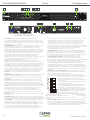
6 7 85432 9
1411 1210
1
1513
LT SERIES OPERATION
»1. MOUNTING
are normally used to secure the amp to the front and rear of the gear rack. All
»2. BRIDGE MODE
can be run with both channel pairs in bridge mode giving you two high
of channels in bridge mode and the other pair of channels in stereo, giving
speaker connectors may be used at the same time when in bridge mode! Use
»3. TEMP
operating temperature exceeds the safe operating limit of the amplifier and
the temperature protection is activated. When activated, the power output of
the amplifier is reduced, allowing the internal amplifier temperature to return
to the safe operating range while still producing audio. The TEMP LED
air is restricted,
hot air to escape, or
»4. POWER
powered up.
»5. CHANNEL LEVEL CONTROL
reducing the headroom of the signal source, the level controls should be
turned full on.
»6. PROTECT
draws excessive current or a direct short is detected caused by a shorted
speaker cable or speaker system. Reset this condition by turning the amp off
for two seconds and then on again. Check for shorted cables and that the
»7. CLIP
its maximum clean output. Occasional flashing caused by low frequency
peaks are normal and will not harm speakers capable of handling
damage to the amp.
»8. SIGNAL
the channel.
»9. POWER ON/OFF
making sure the rear plug is fully inserted before engaging the power switch.
»10. AC POWER
use outside of North American will need to replace the EDISON plug with the
back the latch on top of the connector with your thumb and twist the
the amp will require service. Each amp will require a dedicated
circuit breaker for the amp to achieve its full output
»11. SPEAKER OUTPUT
applications. Secure the Twist-Lock cable connection by turning to the
right to the lock position. Twist-Lock outputs are compatible with standard
70V DISTRIBUTION SYSTEM
be connected to an amplifier, divide the output wattage of the amplifier by
the average wattage of all the speakers as one number. Another advantage
of a distribution system is the reduction of the wire size to drive a number of
speakers.
12. SENSITIVITY / AMPLIFIER MODES
input signal is required to achieve full power output from the amplifier. The
becomes. To change the sensitivity, move the dip
on the diagram.
limiter automatically reduces the signal to prevent
hard clipping, which helps protects the drivers. It is
recommended to keep the limiter ON. To turn the limiter
13. COOLING FANS
are designed to draw cold air from the
front panel and exhaust the heat from the rear panel. Maintain a minimum
powered applications. Inadequate ventilation will activate the
thermal protection prematurely. The front cooling vents are not to be
restricted.
»14 & 15 CHANNEL INPUTS
PFC Professional Series
PROTECT POWER
TEMP
CLIP
SIG
CLIP
SIG
CHANNEL CHANNEL 2
PROTECT
BRIDGE
ON
OFF
PFC Professional Series
BRIDGE CH + = POS = NEG
BRIDGE CH + = POS = NEG
PFC Professional Series
TEMP
CLIP
SIG
CLIP
SIG
CHANNEL 3CHANNEL 4
PROTECT PROTECTPROTECT POWER
TEMP
CLIP
SIG
CLIP
SIG
CHANNEL CHANNEL 2
PROTECT
BRIDGE BRIDGE
PFC Professional Series
OHM 34W/CH - 1180W x 1CH BRIDGE
4 OHM 580W/CH - 2010W x 1CH BRIDGE
2 OHM 1010W/CH
BRIDGE CH + = POS ; = NEG
PFC Professional Series
PROTECT POWER
TEMP
CLIP
SIG
CLIP
SIG
CHANNEL CHANNEL 2
PROTECT
BRIDGE
ON
OFF
ON
OFF
+2dBu
+4dBu
+8dBu
+12dBu
INPUT SENSITIVITY
MONO/BRDG
LIMITER OFF
PFC Professional Series
BRIDGE CH + = POS = NEG
100-240VAC 50-60Hz
100-240VAC 50-60Hz
100-240VAC 50-60Hz
+2dBu
+4dBu
+8dBu
+12dBu
INPUT SENSITIVITY
MONO/BRDG
LIMITER OFF
+2dBu
+4dBu
+8dBu
+12dBu
INPUT SENSITIVITY
MONO/BRDG
LIMITER OFF
+2dBu
+4dBu
+8dBu
+12dBu
INPUT SENSITIVITY
MONO/BRDG
LIMITER OFF
OHM W/CH - W x CH BRIDGE
4 OHM W/CH - W x CH BRIDGE
2 OHM W/CH
OHM W/CH - W x CH BRIDGE
OHM W/CH - W x CH BRIDGE
OHM W/CH
PFC Professional Series
PROTECT POWER
TEMP
CLIP
SIG
CLIP
SIG
CHANNEL CHANNEL 2
PROTECT
BRIDGE
ON
OFF
PFC Professional Series
BRIDGE CH + = POS = NEG
BRIDGE CH + = POS = NEG
PFC Professional Series
TEMP
CLIP
SIG
CLIP
SIG
CHANNEL 3CHANNEL 4
PROTECT PROTECTPROTECT POWER
TEMP
CLIP
SIG
CLIP
SIG
CHANNEL CHANNEL 2
PROTECT
BRIDGE BRIDGE
PFC Professional Series
OHM 34W/CH - 1180W x 1CH BRIDGE
4 OHM 580W/CH - 2010W x 1CH BRIDGE
2 OHM 1010W/CH
BRIDGE CH + = POS ; = NEG
PFC Professional Series
PROTECT POWER
TEMP
CLIP
SIG
CLIP
SIG
CHANNEL CHANNEL 2
PROTECT
BRIDGE
ON
OFF
ON
OFF
+2dBu
+4dBu
+8dBu
+12dBu
INPUT SENSITIVITY
MONO/BRDG
LIMITER OFF
PFC Professional Series
BRIDGE CH + = POS = NEG
100-240VAC 50-60Hz
100-240VAC 50-60Hz
100-240VAC 50-60Hz
+2dBu
+4dBu
+8dBu
+12dBu
INPUT SENSITIVITY
MONO/BRDG
LIMITER OFF
+2dBu
+4dBu
+8dBu
+12dBu
INPUT SENSITIVITY
MONO/BRDG
LIMITER OFF
+2dBu
+4dBu
+8dBu
+12dBu
INPUT SENSITIVITY
MONO/BRDG
LIMITER OFF
OHM W/CH - W x CH BRIDGE
4 OHM W/CH - W x CH BRIDGE
2 OHM W/CH
OHM W/CH - W x CH BRIDGE
OHM W/CH - W x CH BRIDGE
OHM W/CH
AQ2450
PFC Professional Series
PFC Professional Series
PFC Professional Series
PFC Professional Series
AQ2450
PFC Professional Series
PFC Professional Series
PFC Professional Series
PFC Professional Series
-
 1
1
-
 2
2
-
 3
3
-
 4
4
-
 5
5
-
 6
6


Carvin Audio LT5204 Manuale utente
- Categoria
- Set di altoparlanti
- Tipo
- Manuale utente
in altre lingue
- English: Carvin Audio LT5204 User manual
Altri documenti
-
SOUNDIGITAL 600.4 EVO5 Manuale del proprietario
-
HELVIA ZEUS X Series Manuale utente
-
dBTechnologies A4TI Manuale utente
-
LD Systems IPA 412 T Manuale del proprietario
-
Audio Design GTi4100 Manuale utente
-
Blaupunkt VR 6000 Manuale del proprietario
-
A.E.B. HPA 1400 Manuale utente
-
MarkBass Bass Multiamp Scheda dati
-
-