
P-2014
1x4 CAT5 Audio Distribution Module
8
4
A
T
Aud
o D
istri
but o
odu
e
1 C
5
i i
n
M
l
u
(Req
ired)
P
wer
o
(
ptional)
O
tat s
S
u
ystemS
y
em
S st
I pu
n
t
Lo al
c
Input
o
Z ne 1
on 2
Z
e
on 3
Z e
on 4Z e
xp
si
E an
on
u p
O t ut
Local
P
o t
ri ri y
gn
Si al
L
R
E t
mi
ters
R
O
P
C A N N
E L
H
TM
I S
I N
V
O
C A N N
E L
H
I S
I N
V
O
TM
IR
x
T
M
E S
I
C
H
A
N
N L
V
I
O
N
P
1Mod
e
l -2
0
4

C
i d
1 4
A
T5
Aud
io D
istr
bution M
o ule
(R
u
eq
ired)
e
Pow
r
(O tional
p
)
S
tu
ta s
Sy tem
s
Sy m
ste
p
In ut
L
o
c la
t
In
p
u
Zone 1
o
Z ne 2
on 3
Z e
o
Z ne 4
p
n i
n
Ex a s o
Outp
t
u
Local
rio iP
r ty
Si
agn
l
L
R
Emitte
rs
RP
O
N
N
C H
A E L
TM
V
O
NI
S I
N
N
C H
A E L
V
O
NI
S I
TM
IR
x
TM
H
N
N E
L
S
I N
C A V I
O
o 4
M d
e
l P-
20
1
2
3
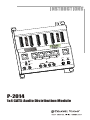
The P-2014 functions as the heart of you're CAT5 audio system. It is a
1x4 distribution module that delivers audio signals and power to 4
keypads (model A0125). 4 IR emitter outputs on the P-2014 allow IR
signals detected by the A0125 to control source devices such as CD
players and AM/FM tuners. The A0125 acts as the volume control for the
A0240 40Watt in-room amplifier.
4 Global IR emitters will flash when any
keypad in the system detects an IR signal.
Power supply connection (included).
Optional Status power connection (for future use).
Expansion connectors are used to hook up additional units for more
CAT5 audio outputs.
Connection LEDs light when the A0125 keypad is attached. Only 4
keypads (1 per zone) can be powered at a time. If both RJ-45 and
110 connectors are used, the RJ-45 will have priority.
System Input from model A0301, A0313, or expansion output.
Local Input
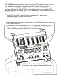
Required components
Optional components
!
Both RJ-45 and 110 punch down connectors for easy setup
!
Integrated single source audio input
!
4 common IR emitter outputs
A0125 ... 1 per listening zone. Acts as volume control for the
A0240 and relays IR information. Mount the keypad in single
gang low-voltage ring or J-box (if required by code).
Compatible with Decorator style wall plates. Blue LEDs show
volume level. Keypad completely mutes when bottom LED is
off.
A0302 ... 1 per every A0125. Transfers line-level audio into the
A0240 and takes speaker-level audio from the A0240 and
connects it to the speakers.
IR-3002 & IR-3001 ... Single and dual head IR flashers. Use
one head per source to control from the remote room.
A0505 ... Remote control. Compatible with: A0125, P-2044,
P-6014, A4603, and many other Channel Vision products.
A0301 ... Universal input module. Can be used to provide
local source input in any room and/or act as the main system
input feeding into the hub. The A0301 is a great way to enable
simple connection of local sources into the zone - TV’s, MP3
players, computer sources, etc.
A0313 ... Wall Docking Station for . Can be used inject
the iPod as a local source input in any room and/or act as the
main system input feeding into the hub. The A0313 can
extract audio from and will
charge* the iPod when not in use.
®
iPod
any iPod with a dock connector
Line level inputsLine level inputs
IR emittersIR emitters
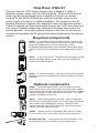
How Does it Work?
Channel Vision’s CAT5 Audio System uses Category 5 cable to
distribute power, audio, and IR control signals. Power and line-level
audio signals are delivered to the keypads which act as volume
controls for the A0240 40Watt per channel amplifier which in turn
power a pair of in-wall or in-ceiling speakers. The keypads have IR
sensors that detect signals from standard hand held remote controls.
These IR signals are then transmitted through the CAT5 wire back to a
hub or input module where they activate IR emitters that control the
source devices. IR emitters attach directly to the front of the source
devices and recreate the IR signals that were produced by the remote
control.
A0240 ... 2-channel Amplifier. 1 per every A0125. Provides 40
Watts per channel of amplification to drive in-wall or in-ceiling
speakers.
Source
CH AN NEL VIS IO N
Pwr
CH ANN EL V ISI ON
S
O
U
R
C
E
ZONE
POWER
MUTE
4
3
2
1
CAMERA
CATV
MOD
VOL
1
2
3
4
MODEL
A0505
POWER
Amp-Link
Channel Vision
R
L/S
Line Out

4
C
d
o
i tri u
on
Mod
l
1
A
T5
Au
i D s
b ti
u e
(Re
ui d
q
re )
P
we
o r
(O a
ption
l)
Status
Sy
m
ste
Sy
tems
I pu
n t
L
o
c l
a
Inp
t
u
o
Z ne 1
one 2
Z
o
Z
ne 3
on
4Z e
Expansion
Outpu
t
o
a
L c l
Priorit
y
Signal
L
R
rsEmitte
P
RO
H
N
N E L
C A
TM
V
I O
N
S I
H
N
N E L
C A
V
I O
N
S I
TM
IR
x
TM
H
N
N E
L
S
I N
C A V I
O
o 4
M d
e
l P-
20
1
2
3
The P-2014 functions as the heart of you're CAT5 audio system. It is a
1x4 distribution module that delivers audio signals and power to 4
keypads (model A0125). 4 IR emitter outputs on the P-2014 allow IR
signals detected by the A0125 to control source devices such as CD
players and AM/FM tuners. The A0125 acts as the volume control for the
A0240 40Watt in-room amplifier.
4 Global IR emitters will flash when any
keypad in the system detects an IR signal.
Power supply connection (included).
Optional Status power connection (for future use).
Expansion connectors are used to hook up additional units for more
CAT5 audio outputs.
Connection LEDs light when the A0125 keypad is attached. Only 4
keypads (1 per zone) can be powered at a time. If both RJ-45 and
110 connectors are used, the RJ-45 will have priority.
System Input from model A0301, A0313, or expansion output.
Local Input
Required components
Optional components
!
Both RJ-45 and 110 punch down connectors for easy setup
!
Integrated single source audio input
!
4 common IR emitter outputs
A0125 ... 1 per listening zone. Acts as volume control for the
A0240 and relays IR information. Mount the keypad in single
gang low-voltage ring or J-box (if required by code).
Compatible with Decorator style wall plates. Blue LEDs show
volume level. Keypad completely mutes when bottom LED is
off.
A0302 ... 1 per every A0125. Transfers line-level audio into the
A0240 and takes speaker-level audio from the A0240 and
connects it to the speakers.
IR-3002 & IR-3001 ... Single and dual head IR flashers. Use
one head per source to control from the remote room.
A0505 ... Remote control. Compatible with: A0125, P-2044,
P-6014, A4603, and many other Channel Vision products.
A0301 ... Universal input module. Can be used to provide
local source input in any room and/or act as the main system
input feeding into the hub. The A0301 is a great way to enable
simple connection of local sources into the zone - TV’s, MP3
players, computer sources, etc.
A0313 ... Wall Docking Station for . Can be used inject
the iPod as a local source input in any room and/or act as the
main system input feeding into the hub. The A0313 can
extract audio from and will
charge* the iPod when not in use.
®
iPod
any iPod with a dock connector
Line level inputsLine level inputs
IR emittersIR emitters
How Does it Work?
Channel Vision’s CAT5 Audio System uses Category 5 cable to
distribute power, audio, and IR control signals. Power and line-level
audio signals are delivered to the keypads which act as volume
controls for the A0240 40Watt per channel amplifier which in turn
power a pair of in-wall or in-ceiling speakers. The keypads have IR
sensors that detect signals from standard hand held remote controls.
These IR signals are then transmitted through the CAT5 wire back to a
hub or input module where they activate IR emitters that control the
source devices. IR emitters attach directly to the front of the source
devices and recreate the IR signals that were produced by the remote
control.
A0240 ... 2-channel Amplifier. 1 per every A0125. Provides 40
Watts per channel of amplification to drive in-wall or in-ceiling
speakers.
Source
CH AN NEL VIS IO N
Pwr
CH ANN EL V ISI ON
S
O
U
R
C
E
ZONE
POWER
MUTE
4
3
2
1
CAMERA
CATV
MOD
VOL
1
2
3
4
MODEL
A0505
POWER
Amp-Link
Channel Vision
R
L/S
Line Out

Amp-Link
Channel Vision
R
L/S
Line Out
Amp-Link
Channel Vision
R
L/S
Line Out
Amp-Link
Channel Vision
R
L/S
Line Out
Amp-Link
Channel Vision
R
L/S
Line Out
Amp-Link
Channel Vision
R
L/S
Line Out
1 4
CA
T5 Audi
Di
ib Modul
o
str
ution
e
(Required
)
Power
(Optional
)
S
a st tu
m
Syste
y m
S
ste
u
Inp
t
o
lL
ca
In
pu
t
Zone 1
Zone 2
Zone 3
Zone 4
Expan
io
s
n
Output
Local
Priority
Sig aln
L
R
Emitt rs
e
P
R
O
H
N E
C A
N
L
M
T
I O NV
I
S
H
N E
C A
N
L
I O NV
I
S
M
T
IR
x
M
T
CH AN NEL
V
IS IO
N
e 4M
od
l
P
-
2
01
SUB L/R
R+
L+L-R-R+
R- L-
L+
JP1
JP2
JP3
GND
TB1
24V
PWR
GND
SW2
L/R
IN
SPKRS
IN
1 4
CAT5 Audi
Di
ib on Modul
o
str
uti
e
d
(Require
)
Power
(Optional)
Sta us
t
y m
S
ste
y m
S
ste
pu
In
t
o
lL
ca
I
p
t
n
u
Zone 1
Zone 2
Zone 3
Z
e
on
4
Expansion
O
p
ut
ut
L
l
oca
Pr r
io
ity
Sig aln
L
R
Emitt rs
e
PR
O
H
N E
C A
N
L
M
T
V
S
I O N
I
H
N E
C A
N
L
V
S
I O N
I
M
T
IR
x
TM
C
HA
NE L
I S NN
V
IO
M
d
e
-
2
014
o l
P
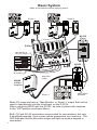
A0240
40Watt
Amplifier
P-2014
A0125
(Rear)
A0302
(Rear)
Tape Monitor or
Room 2 output
(Optional)
IR emitters
Amp-Link
Cable
Sat radio
DVD player
CD player
Receiver
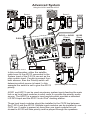
A0301 and A0313 can be used as primary system inputs feeding the main
hub or as local input modules in each room to override the primary audio
source. The A0301 is a generic input module which provides a standard
®
L/R RCA input and the A0313 is an iPod docking station.
These local input modules should be installed in the CAT5 line between
the P-2014 and the A0125. Multiple input modules can be installed in one
CAT5 run. If audio is present at more than one input module the unit
closest to A0125 will take priority and be played through the speakers.
In this configuration, either the satellite
radio tuner or the A0313 connected to the
System Input of the P-2014 can act as the
main system input. If audio is present from
both sources, then the Priority switch will
determine which source is heard. In this
example the switch is set to give the A0313
priority.
Most A/V receivers have a ‘Tape Monitor’ or ‘Room 2’ output that can be
used to feed directly into the local input on the P-2014.
When using the A0302 with the A0125, be sure to place both switches
in the “L/R” position as shown above.
Both 110 and RJ-45 connectors are provided for convenience, but only
4 amplified keypads (1 per zone) can be powered at any one time. The
LED indicator next to the active output will light up when a keypad is
connected
Basic System Advanced System
5
4
Make all connections before applying power.
Using the A0301 and the A0313
Source
CHANNEL V ISION
Pwr
Source
CHANNEL V IS ION
Pwr
Source
CHANNEL V IS ION
Pwr
Source
CHANNEL V ISION
Pwr
Room 1
Room 1 Room 3
A0313A0301
Room 3
Room 4
Note switch
positions
P-2014
A0313 or A0301
(Rear)
A0125
(Rear)
A0302
OUT
U
T
O
IN
I
N
Line level inputs
IR emitters
A0313
Secondary audio source
Primary audio source
(See Basic System for details)
Sat radio

Amp-Link
Channel Vision
R
L/S
Line Out
Amp-Link
Channel Vision
R
L/S
Line Out
Amp-Link
Channel Vision
R
L/S
Line Out
Amp-Link
Channel Vision
R
L/S
Line Out
Amp-Link
Channel Vision
R
L/S
Line Out
1 4 CAT5 Audio
Distribution
Module
r d
(Requi
e
)
r
Powe
O io
( pt nal)
Status
y m
S
ste
ys m
S
te
npuI
t
o
al
L
c
I
p
t
n
u
Z
e
on
1
Z
e
on
2
Zone 3
Z
ne
4o
p
n
io
Ex a
s n
O
tpu
ut
L
c
l
o
a
Pr
or ty
i
i
Sig
al
n
L
R
E t
mit ers
R
P
O
C
H N
N E
A L
TM
V
I
S I O N
C
H N
N E
A L
V
I
S I O N
TM
IR
x
T
M
CH A
NN EL
VI SIO
N
e
M
od
l
P
-
2
014
SUB L/R
R+
L+L-R-R+
R- L-
L+
JP1
JP2
JP3
GND
TB1
24V
PWR
GND
SW2
L/R
IN
SPKRS
IN
b
l
1
4 CA
T5 Audio
Distri ution
Modu e
R
ir
d
(
equ e )
P
r
owe
(O tio
p nal)
Status
ys m
S
te
ys
em
S
t
Input
Lo
alc
Inp
t
u
Z
e 1on
Z
e
on
2
Z
e
on
3
Z ne 4o
E p
n io
x a
s n
O
tpu
ut
L c
l
o
a
Prior
ty
i
S
l
igna
L
R
E tt rmi e s
R
P
O
H
E
C A
N
N
L
M
T
V I
S
I O
N
H
E
C A
N
N
L
V I
S
I O
N
M
T
IR
x
M
T
C
HA
NE L
IS NN V
IO
M
d
e -2
014
o l
P
A0240
40Watt
Amplifier
P-2014
A0125
(Rear)
A0302
(Rear)
Tape Monitor or
Room 2 output
(Optional)
IR emitters
Amp-Link
Cable
Sat radio
DVD player
CD player
Receiver
A0301 and A0313 can be used as primary system inputs feeding the main
hub or as local input modules in each room to override the primary audio
source. The A0301 is a generic input module which provides a standard
®
L/R RCA input and the A0313 is an iPod docking station.
These local input modules should be installed in the CAT5 line between
the P-2014 and the A0125. Multiple input modules can be installed in one
CAT5 run. If audio is present at more than one input module the unit
closest to A0125 will take priority and be played through the speakers.
In this configuration, either the satellite
radio tuner or the A0313 connected to the
System Input of the P-2014 can act as the
main system input. If audio is present from
both sources, then the Priority switch will
determine which source is heard. In this
example the switch is set to give the A0313
priority.
Most A/V receivers have a ‘Tape Monitor’ or ‘Room 2’ output that can be
used to feed directly into the local input on the P-2014.
When using the A0302 with the A0125, be sure to place both switches
in the “L/R” position as shown above.
Both 110 and RJ-45 connectors are provided for convenience, but only
4 amplified keypads (1 per zone) can be powered at any one time. The
LED indicator next to the active output will light up when a keypad is
connected
Basic System Advanced System
5
4
Make all connections before applying power.
Using the A0301 and the A0313
Source
CHANNEL V ISION
Pwr
Source
CHANNEL V IS ION
Pwr
Source
CHANNEL V IS ION
Pwr
Source
CHANNEL V ISION
Pwr
Room 1
Room 1 Room 3
A0313A0301
Room 3
Room 4
Note switch
positions
P-2014
A0313 or A0301
(Rear)
A0125
(Rear)
A0302
OUT
OU
T
IN
I
N
Line level inputs
IR emitters
A0313
Secondary audio source
Primary audio source
(See Basic System for details)
Sat radio

1 4 A
5
udio D
is ribution Modu
le
C
T A
t
R
( equired)
er
Pow
(O
tional
p
)
a
St tus
yst m
S e
System
nput
I
ca
l
Lo
Inp
ut
1
Zone
Zone 2
Zone 3
Zone 4
xpansionE
Output
Local
Priority
Signal
L
R
Emit
ers
t
PR
O
C H
N
N E
A
L
TM
I
S O
V
I N
C H
N
N E
A
L
I
S O
V
I N
TM
IR
x
M
T
A
S
ON
H
NN
EL
V
C I
I
Mo el
P
d
-
20
14
1
4 CA
5
udio Distribution Mo
dule
T
A
R red(
equi )
owerP
t
(O ional)
p
a
St
tus
yst mS
e
System
Input
calLo
I
p
n ut
1Zone
Zone 2
Zone 3
Zone 4
xpansion
E
Output
Local
t
Priori
y
Signal
L
R
Emitters
PR
O
C
H
A N N E
L
TM
OV I S I
N
C
H
A N N E
L
OV I S I
N
TM
IR
x
M
T
C
HA N
L
IS IO
N
NE
V
M
od
e
l
P-2
01
4
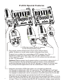
P-2014 Special Features
The priority switch determines which input will be heard
(either System or Local) when audio is sensed from both.
Expand your system by connecting a CAT5 jumper from the
expansion output to of the first P-2014 to the System input
of the second P-2014. Use either the RJ-45 connectors (as shown)
or the 110 connector.
Optional Status power input senses when a connector is plug into it.
This connection has the potential to disrupt some of the automatic
switching features built into the A0125 keypad. It exists for future uses
only and potential applications will be described in future manuals.
Keypad connection LEDs light when an a keypad is attached.
If a keypad is attached to the 110 connector, the LED below it will light.
If a keypad is attached to the RJ-45 connector, the LED below it will light.
If a keypad is attached to both connectors, the LED below the RJ-45 will
light and only the keypad connected to the RJ-45 will be active.
A maximum of 4 keypads (1 per zone) can be powered from each P-2014.
Note: the LED below the RJ-45 glows dimly even when the 110 connector
is used. This is to indicate that the RJ-45 connection always takes priority.
LEDs light when audio is sensed
on the corresponding input.
6
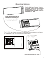
The P-1300 from Channel Vision’s
Pro-series product line is the perfect
home for the P-2014. The P-1300
is a hinged plate designed to fit into
a standard 19” rack.
The P-1300 hinges open to
maintain a clean look and
provide easy access for
servicing equipment.
The P-2014 can also be mounted in a standard structured wiring enclosure
or screwed to a wall or flat surface as shown below.
Cut or remove the
nylon snap pin.
Install screws in empty holes.
Mounting Options
7
1 4 CAT5 Audio Distribution Module
Required
Power
(Optional)
Status
System
System
Input
Local
Input
Zone 1 Zone 2 Zone 3 Zone 4
Expansion
Output
Local
Priority Signal
L R
Emitters
PRO
CH AN NEL
TM
VI SI ON
CH AN NEL
VI SI ON
TM
IR
x
R qu red
e i
Power
(Opt n
io
al)
t u
S at s
Sy tem
s
l
Loca
Inp
ut
ocal
L
ior
y
Pr
it
g
Si nal
L
R
tt
r
Emi e s
P
R
O
C
HA NNE
L
TM
VI
SI ON
C
HA NNE
L
VI
SI ON
TM
1 4 CA
T5
istribution M dule
D o
IR
x
+
4 DC
2
V
P
w ro e
+ 2
D1
V C
S at s
t
u
t
Sys em
c
Lo
al
Inp
ut
oca
L
l
Pr
or
ti
i y
gn
l
Si a
L
R
s
Emitter
ROP
C HA NN
E
L
TM
V
IS
IO
N
C HA NN
E
L
V
IS
IO
N
TM
1 AT5 A di
trib
M
du
4
C
u
o Dis
ution
o le
IR
x
-
M
T
C A
N
NEL
S
O
N
H
V
I
I
o
d l -2
1
M e
P 0 4
TM
CHA
N
NEL V
ISI
O
N
-
2
4M
o
d
e
l
P 01
)
(Op
tion
al
TM
CHA NNE L VI SIO N
Model P-2014

4
i
i
n M le
1
CAT5 Audio D
stribut
o
odu
(Required)
Power
O
t
o l
(
p
i
na
)
a us
St t
System
tSys em
Input
L
ca
l
o
I pu
n
t
Zone 1
Zone 2
3
Zone
Zone 4
Expansion
u
O tput
Lo
al
c
rior
tP i
y
Signal
L
R
r
Emitte
s
PRO
C H
N
N
E L
A
TM
V
I
S O
I N
C H
N
N
E L
A
V
I
S O
I N
TM
RI
x
M
T
S
ONH
A
NN E
L
V
C I
I
Mo e P
d
l
-
20
14
1 4 is i
n M
dule
CA
T5 Audio
D tribut o o
(Required)
Power
O t onal
( p i
)
ta usS
t
System
stSy
em
Input
L cal
o
I
pu
n t
Zone 1
Zone 2
3Zone
4
Zone
o
Expansi n
ut
O
put
Local
riorit
P
y
Signal
L
R
r
Emitte s
P
RO
C
H NN EA L
TM
I S
O
V I
N
C
H NN EA L
I S
O
V I
N
TM
R
I
x
M
T
C
HA L
IS
IO
N
N
NE
V
M
od
e
l
P-2
01
4
P-2014 Special Features
The priority switch determines which input will be heard
(either System or Local) when audio is sensed from both.
Expand your system by connecting a CAT5 jumper from the
expansion output to of the first P-2014 to the System input
of the second P-2014. Use either the RJ-45 connectors (as shown)
or the 110 connector.
Optional Status power input senses when a connector is plug into it.
This connection has the potential to disrupt some of the automatic
switching features built into the A0125 keypad. It exists for future uses
only and potential applications will be described in future manuals.
Keypad connection LEDs light when an a keypad is attached.
If a keypad is attached to the 110 connector, the LED below it will light.
If a keypad is attached to the RJ-45 connector, the LED below it will light.
If a keypad is attached to both connectors, the LED below the RJ-45 will
light and only the keypad connected to the RJ-45 will be active.
A maximum of 4 keypads (1 per zone) can be powered from each P-2014.
Note: the LED below the RJ-45 glows dimly even when the 110 connector
is used. This is to indicate that the RJ-45 connection always takes priority.
LEDs light when audio is sensed
on the corresponding input.
6
The P-1300 from Channel Vision’s
Pro-series product line is the perfect
home for the P-2014. The P-1300
is a hinged plate designed to fit into
a standard 19” rack.
The P-1300 hinges open to
maintain a clean look and
provide easy access for
servicing equipment.
The P-2014 can also be mounted in a standard structured wiring enclosure
or screwed to a wall or flat surface as shown below.
Cut or remove the
nylon snap pin.
Install screws in empty holes.
Mounting Options
7
1 4 CAT5 Audio Distribution Module
Required
Power
(Optional)
Status
System
System
Input
Local
Input
Zone 1 Zone 2 Zone 3 Zone 4
Expansion
Output
Local
Priority Signal
L R
Emitters
PRO
CH AN NEL
TM
VI SI ON
CH AN NEL
VI SI ON
TM
IR
x
R
qu
red
e i
Power
(Opt n l
io
a
)
t u
S at s
y e
S st
m
l
Loca
Inp
ut
c
l
Lo
a
r
Prio
ity
Signal
L
R
tters
Emi
P
R
O
H N
C
A
NE L
TM
VI
SI ON
H N
C
A
NE L
VI
SI ON
TM
1
CA
T5
i i
i dul 4
D str but
on Mo e
IR
x
+24
DC
V
P
w ro e
+ 2
D1
V C
S atus
t
Syst m
e
Loc l
a
In
up
t
o
L
cal
oPri
rity
g
Si nal
L
R
e s
Emitt
r
P
RO
C A
N
L
H N
E
TM
V
IS
IO
N
C A
N
L
H N
E
V
IS
IO
N
TM
1 AT5 Audi
D strib
on Modu e4
C
o
i
uti l
IR
x
-
M
T
C
A
N
NEL
S
O
N
H
V
I
I
o
d l -2
1
M e
P 0 4
TM
CHA
N
NEL V
IS
I
O
N
-
2
4
M
o
d
e
l
P 01
(
pt
o l)
O
i
na
TM
CHA NNE L VI SIO N
Model P-2014

CHANNEL VISION
Limited Warranty
Channel Vision Technology will repair or replace any defect in material or
workmanship which occurs during normal use of this product with new or
rebuilt parts, free of charge in the USA, for two years from the date of
original purchase. This is a no hassle warranty with no mail in warranty
card needed. This warranty does not cover damages in shipment, failures
caused by other products not supplied by Channel Vision Technology, or
failures due to accident, misuse, abuse, or alteration of the equipment. This
warranty is extended only to the original purchaser, and a purchase receipt,
invoice, or other proof of original purchase date will be required before
warranty repairs are provided.
Mail in service can be obtained during the warranty period by calling (800)
840-0288 toll free. A Return Authorization number must be obtained in
advance and can be marked on the outside of the shipping carton.
This warranty gives you specific legal rights and you may have other rights
(which vary from state to state). If a problem with this product develops
during or after the warranty period, please contact Channel Vision
Technology, your dealer or any factory-authorized service center.
500-207 rev A
Specifications: (typical)
Power Supply: 18VDC, 1.0Amp
Audio Input Max Level: 5 Vp-p
IR Frequency range supported: 30 kHz - 56 kHz
Dimensions: 6"W x 6.5"H x 1.25"D
Specifications subject to change without notice.
-
 1
1
-
 2
2
-
 3
3
-
 4
4
-
 5
5
-
 6
6
-
 7
7
-
 8
8


