
A0301
Universal Input Module
For CAT5 Audio Systems
8
Line level inputs
IR emitters

2
3
OR
A0125
Volume Control Keypad:
Speakers:
In-ceiling, In-wall and free-standing 8 ohm speakers are acceptable.
Features:
!
!
Senses audio to automatically override the main audio source
!
Provides 2 IR emitter outputs
!
Uses CAT5 cabling
Compatible with Channel Vision’s CAT5 Audio Systems
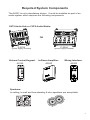
The A0301 is not a standalone device. It must be installed as part of an
audio system which requires the following components:
Required System Components
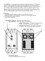
The A0301 is a universal input module for Channel Vision’s CAT5 A
Systems that can accept audio from any standard L/R line-level audio
source. The attractive decorator style faceplate allows the unit to blend in
with modern light switches and outlets. It can be used to provide local
source input in any room and/or as the main system input device. The
A0301 is a great way to enable simple connection of local sources such
as TV’s, MP3 players, and computer sources into the zone.
udio
CAT5 Audio Hub or CAT5 Audio Matrix:
P-2014
(power supply included)
P-2044
(power supply included)
A0240 A0302
In-Room Amplifier: Wiring Interface:
Source
CHA NN EL V IS IO N
Pwr
1 4 CAT5
Audio Distribution Module
(Required)
Power
(Optional)
Status
System
System
Input
Local
Input
Zone 1
Zone 2
Zone 3
Zone 4
Expansion
Output
Local
Priority
Signal
L
R
Emitters
PRO
CH AN N
EL
TM
V
IS
I
ON
IR
x
TM
C
H
AN
NEL
VI
S
I
ON
Model P-2014
Amp-Link
Channel Vision
R
L/S
Line Out
PRO
CH AN NEL
TM
VI SI ON
Active
Active
Active
Active
Link
In
Link
Out
Zone 1
Zone 2
Zone 3
Zone 4
Source 1 Source 2
Source 3
Source 4
Common IR
Source 4 IR
Source 3 IR
Source 2 IRSource 1 IR
IR Data
Power
TM
CH
AN
NEL V ISI ON
Model P-2044
Line level inputs
IR emitters
OUT
OUT
IN
IN
L/R Audio Inputs...
Connect standard audio sources
IR Emitter Outputs... Connect IR emitters here
Input Connectors... 110 and RJ-45 inputs for
CAT5 - use one or the other (not both)
Output Connectors... 110 and RJ-45 inputs
for CAT5 - use one or the other (not both)
LED Indicator... Flashes when IR is present

2
3
OR
A0125
Volume Control Keypad:
Speakers:
In-ceiling, In-wall and free-standing 8 ohm speakers are acceptable.
Features:
!
!
Senses audio to automatically override the main audio source
!
Provides 2 IR emitter outputs
!
Uses CAT5 cabling
Compatible with Channel Vision’s CAT5 Audio Systems
The A0301 is not a standalone device. It must be installed as part of an
audio system which requires the following components:
Required System Components
The A0301 is a universal input module for Channel Vision’s CAT5 A
Systems that can accept audio from any standard L/R line-level audio
source. The attractive decorator style faceplate allows the unit to blend in
with modern light switches and outlets. It can be used to provide local
source input in any room and/or as the main system input device. The
A0301 is a great way to enable simple connection of local sources such
as TV’s, MP3 players, and computer sources into the zone.
udio
CAT5 Audio Hub or CAT5 Audio Matrix:
P-2014
(power supply included)
P-2044
(power supply included)
A0240 A0302
In-Room Amplifier: Wiring Interface:
Source
CHA NN EL V IS IO N
Pwr
1 4 CAT5
Audio Distribution Module
(Required)
Power
(Optional)
Status
System
System
Input
Local
Input
Zone 1
Zone 2
Zone 3
Zone 4
Expansion
Output
Local
Priority
Signal
L
R
Emitters
PRO
CH AN N
EL
TM
V
I
S
I
ON
IR
x
TM
CH
AN
NEL
VI
SIO N
Model P-2014
Amp-Link
Channel Vision
R
L/S
Line Out
PRO
CH AN NEL
TM
VI SI ON
Active
Active
Active
Active
Link
In
Link
Out
Zone 1
Zone 2
Zone 3
Zone 4
Source 1 Source 2
Source 3
Source 4
Common IR
Source 4 IR
Source 3 IR
Source 2 IRSource 1 IR
IR Data
Power
TM
CH
AN
NEL V ISI ON
Model P-2044
Line level inputs
IR emitters
OUT
OUT
IN
IN
L/R Audio Inputs...
Connect standard audio sources
IR Emitter Outputs... Connect IR emitters here
Input Connectors... 110 and RJ-45 inputs for
CAT5 - use one or the other (not both)
Output Connectors... 110 and RJ-45 inputs
for CAT5 - use one or the other (not both)
LED Indicator... Flashes when IR is present

1 4 CA
T5
Audio Distribution Module
(Required)
Power
(Optional)
Status
System
System
Input
Local
Input
Zone 1
Zone 2
Zone 3
Zone 4
Expansion
Output
Local
Priority
Signal
L
R
Emitters
PRO
C
HA N N
EL
TM
V
I
S
IO
N
IR
x
TM
CH AN N
E
L
V
I
S
IO
N
Model P-2014
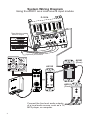
System Wiring Diagram
Using the A0301 as a local source input module
4
5
A0125
P-2014
A0301
(Rear)
A0301
(Front)
Connect the line level audio outputs
of a local audio source, such as a TV,
MP3 player, or computer.
OUT
OUT
IN
IN
Tape Monitor or
Room 2 output
(Optional) IR emitters
Sat radio
DVD player
CD player
Receiver
5
Amp-Link
Channel Vision
R
L/S
Line Out
Amp-Link
Channel Vision
R
L/S
Line Out
Amp-Link
Channel Vision
R
L/S
Line Out
Amp-Link
Channel Vision
R
L/S
Line Out
1 4 CAT5 Audio Distribution Module
(Required)
Power
(Optional)
Status
System
System
Input
Local
Input
Zone 1
Zone 2
Zone 3
Zone 4
Expansion
Output
Local
Priority
Signal
L
R
Emitters
PRO
CH
AN
NE L
T
M
VI SIO
N
IR
x
TM
C
H
AN N
E
L VI S
I
O
N
Model P-2014
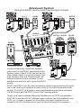
A0301 and A0313 can be used as primary system inputs feeding the main
hub or as local input modules in each room to override the primary audio
source. The A0301 is a generic input module which provides a standard
®
L/R RCA input and the A0313 is an iPod docking station.
These local input modules should be installed in the CAT5 line between
the P-2014 and the A0125. Multiple input modules can be installed in one
CAT5 run. If audio is present at more than one input module the unit
closest to A0125 will take priority and be played through the speakers.
In this configuration, either the satellite
radio tuner or the A0301 connected to the
System Input of the P-2014 can act as the
main system input. If audio is present from
both sources, then the Priority switch will
determine which source is heard. In this
example the switch is set to give the A0301
priority.
Advanced System
Using the A0301 as the main source input module
Source
CH AN NEL V ISI ON
Pwr
Source
CH AN NEL V ISI ON
Pwr
Room 1 Room 3
A0313A0301
P-2014
A0313 or A0301
(Rear)
A0125
(Rear)
A0302
OUT
OUT
IN
IN
A0301
Secondary audio source
Primary audio source
(See A0125 manual for connection details)
Sat radio
Source
CH A N N EL V I S I ON
Pwr
Line level inputs
IR emitters
Line level inputs
IR emitters
Line level inputs
IR emitters
CD Player

1 4 CA
T5
Audio Distribution Module
(Required)
Power
(Optional)
Status
System
System
Input
Local
Input
Zone 1
Zone 2
Zone 3
Zone 4
Expansion
Output
Local
Priority
Signal
L
R
Emitters
PRO
C
HA N N
EL
TM
V
I
S
IO
N
IR
x
TM
CH AN N
E
L V
I
S
I
ON
Model P-2014
System Wiring Diagram
Using the A0301 as a local source input module
4
5
A0125
P-2014
A0301
(Rear)
A0301
(Front)
Connect the line level audio outputs
of a local audio source, such as a TV,
MP3 player, or computer.
OUT
OUT
IN
IN
Tape Monitor or
Room 2 output
(Optional) IR emitters
Sat radio
DVD player
CD player
Receiver
5
Amp-Link
Channel Vision
R
L/S
Line Out
Amp-Link
Channel Vision
R
L/S
Line Out
Amp-Link
Channel Vision
R
L/S
Line Out
Amp-Link
Channel Vision
R
L/S
Line Out
1 4 CAT5 Audio Distribution Module
(Required)
Power
(Optional)
Status
System
System
Input
Local
Input
Zone 1
Zone 2
Zone 3
Zone 4
Expansion
Output
Local
Priority
Signal
L
R
Emitters
PRO
CH
AN
N
EL
T
M
VI S
I
O
N
IR
x
TM
C
H
AN N
E
L VI S
I
O
N
Model P-2014
A0301 and A0313 can be used as primary system inputs feeding the main
hub or as local input modules in each room to override the primary audio
source. The A0301 is a generic input module which provides a standard
®
L/R RCA input and the A0313 is an iPod docking station.
These local input modules should be installed in the CAT5 line between
the P-2014 and the A0125. Multiple input modules can be installed in one
CAT5 run. If audio is present at more than one input module the unit
closest to A0125 will take priority and be played through the speakers.
In this configuration, either the satellite
radio tuner or the A0301 connected to the
System Input of the P-2014 can act as the
main system input. If audio is present from
both sources, then the Priority switch will
determine which source is heard. In this
example the switch is set to give the A0301
priority.
Advanced System
Using the A0301 as the main source input module
Source
CH AN NEL V ISI ON
Pwr
Source
CH AN NEL V ISI ON
Pwr
Room 1 Room 3
A0313A0301
P-2014
A0313 or A0301
(Rear)
A0125
(Rear)
A0302
OUT
OUT
IN
IN
A0301
Secondary audio source
Primary audio source
(See A0125 manual for connection details)
Sat radio
Source
CH A N N EL V I S I ON
Pwr
Line level inputs
IR emitters
Line level inputs
IR emitters
Line level inputs
IR emitters
CD Player

1 4 CAT5 Audio Distribution Module
(Required)
Power
(Optional)
Status
System
System
Input
Local
Input
Zone 1
Zone 2
Zone 3
Zone 4
Expansion
Output
Local
Priority
Signal
L
R
Emitters
PRO
CH
A
N
NE
L
T
M
VI SIO
N
IR
x
TM
C
H
AN N
EL V IS
I
ON
Model P-2014
6
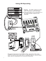
Using IR Repeating
Line level inputs
IR emitters
Sat radio
Inputs ... IR-3002 emitters placed
over IR receiver on all sources.
Connect audio L/R on the A0301 to
the tape monitor output of the
receiver.
IR signals detected by the A0125 will be repeated at the local
A0301 as well as the main A0301, making it easy to control either
main source components or local source devices.
DVD player
CD player
Receiver
Amp-Link
Channel Vision
R
L/S
Line Out
Source
CH A N N E L V I SI O N
Pwr
Line level inputs
IR emitters
1
2
3
4
5
6
7
8
9
0
Power
Local audio source
Sat radio
Local
A0301
Main
A0301
7
Apple and iPod is are trademarks of Apple, Inc., registered in the U.S.
and other countries.
iBus is a registered trademark of Channel Vision Technology.
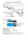
Specifications: (typical @25º C)
Operating Voltage : 18VDC
Cable requirements: CAT5 or better
Operating Temperature: -10ºC to +50ºC
Specifications subject to change without notice.
Stripping and Connecting CAT5 Wire
Blade
CAT5
1. Place the CAT5 between the blade and the first notch of the J-110 tool.
CAT5 cable should be stripped with a proper stripping tool, such as Channel
Vision’s J-110 tool.
Slight
pressure
Rotate
1 turn only
2. Rotate the tool only once. Multiple
turns could damage the inner wires.
3. Inspect the inner wires for damage.
If any wires are cut start over at step 1.
Check for damage
Green/White - Left channel ground
Green - Left channel
Orange/White - Right channel ground
Blue - Signal
Blue/White - Status
Orange - Right channel
Brown/White - Ground
Brown - 24vDC
TIA-568A RJ-45 Modular Plug
Side view:
Top view:

1 4 CAT5 Audio Distribution Module
(Required)
Power
(Optional)
Status
System
System
Input
Local
Input
Zone 1
Zone 2
Zone 3
Zone 4
Expansion
Output
Local
Priority
Signal
L
R
Emitters
PRO
CH
A
NN E
L
T
M
VI SIO
N
IR
x
TM
CH
AN N
EL V
I
S
IO N
Model P-2014
6
Using IR Repeating
Line level inputs
IR emitters
Sat radio
Inputs ... IR-3002 emitters placed
over IR receiver on all sources.
Connect audio L/R on the A0301 to
the tape monitor output of the
receiver.
IR signals detected by the A0125 will be repeated at the local
A0301 as well as the main A0301, making it easy to control either
main source components or local source devices.
DVD player
CD player
Receiver
Amp-Link
Channel Vision
R
L/S
Line Out
Source
CH A N N E L V I SI O N
Pwr
Line level inputs
IR emitters
1
2
3
4
5
6
7
8
9
0
Power
Local audio source
Sat radio
Local
A0301
Main
A0301
7
Apple and iPod is are trademarks of Apple, Inc., registered in the U.S.
and other countries.
iBus is a registered trademark of Channel Vision Technology.
Specifications: (typical @25º C)
Operating Voltage : 18VDC
Cable requirements: CAT5 or better
Operating Temperature: -10ºC to +50ºC
Specifications subject to change without notice.
Stripping and Connecting CAT5 Wire
Blade
CAT5
1. Place the CAT5 between the blade and the first notch of the J-110 tool.
CAT5 cable should be stripped with a proper stripping tool, such as Channel
Vision’s J-110 tool.
Slight
pressure
Rotate
1 turn only
2. Rotate the tool only once. Multiple
turns could damage the inner wires.
3. Inspect the inner wires for damage.
If any wires are cut start over at step 1.
Check for damage
Green/White - Left channel ground
Green - Left channel
Orange/White - Right channel ground
Blue - Signal
Blue/White - Status
Orange - Right channel
Brown/White - Ground
Brown - 24vDC
TIA-568A RJ-45 Modular Plug
Side view:
Top view:

500-209 revA
www.chann e l v i s i o n . c o m
234 Fischer Avenue, Costa Mesa, California 92626 USA
(714)424-6500 (800)840-0288 (714)424-6510 fax
email: [email protected]
Channel Vision Technology will repair or replace any defect in
material or workmanship which occurs during normal use of this
product with new or rebuilt parts, free of charge in the USA, for one
year from the date of original purchase. This is a no hassle warranty
with no mail in warranty card needed. This warranty does not cover
damages in shipment, failures caused by other products not supplied
by Channel Vision Technology, or failures due to accident, misuse,
abuse, or alteration of the equipment. This warranty is extended only
to the original purchaser, and a purchase receipt, invoice, or other
proof of original purchase date will be required before warranty
repairs are provided.
Mail in service can be obtained during the warranty period by calling
(714) 424-6500. A Return Authorization number must be obtained
in advance and can be marked on the outside of the shipping carton.
This warranty gives you specific legal rights and you may have other
rights (which vary from state to state). If a problem with this product
develops during or after the warranty period, please contact Channel
Vision Technology, your dealer or any factory-authorized service
center.
Channel Vision products are not intended for use in medical,
lifesaving, life sustaining or critical environment applications.
Channel Vision customers using or selling Channel Vision products
for use in such applications do so at their own risk and agree to fully
indemnify Channel Vision for any damages resulting from such
improper use or sale.
1
-
 1
1
-
 2
2
-
 3
3
-
 4
4
-
 5
5
-
 6
6
-
 7
7
-
 8
8


