Channel Vision IBUS A0315 Instructions Manual
- Categoria
- Altoparlanti docking
- Tipo
- Instructions Manual

A0315
iBus Wall-Dock for CAT5 Audio Systems
By
TM
0
1

2
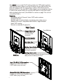
Front/Top
Front/Bottom
Wall Dock
Sliding Dock Platform
Slides up to conceal
the dock connector
Non-Skid Pad
Secures the iPod
Input RJ-45 & 110 Connectors
Connect to CAT5 Audio Hub
CAT5 cable (only use one)
Output RJ-45 & 110 Connectors
Connect to CAT5 Audio Amplifier Input
CAT5 cable (only use one)
Slide Up
Dock Connector
Connects to iPod
Features:
℀
Compatible with all Channel Vision CAT5 audio systems
℀
Charges the iPod
℀
Senses audio to automatically override the main audio source
℀
Supports IR control: compatible with A0505 or Apple Remote
℀
Uses CAT5 cabling
℀
Mounts in a standard 2-gang box
®
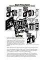
The A0315 is an on-wall iPod docking station for CAT5 audio systems.
The dock connector slides in and out to adjust for any iPod and the non-
skid pad helps to hold the music player in place. With all the popular
features of A0313, the new A0315 adds elegant and contemporary styling
to make it the perfect choice for anyone who wants to enjoy their music
without defacing their wall. (See Made For section on page 3 for a list of
compatible iPods.)
Hinged Dock Lid
Rotates down to
cover the dock
connector
Sliding Dock Lever
Slides the dock connector forward, providing
easy access to dock your iPod

3
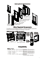
Installing the Trim Plate Accessory
Compatibility
Install Output
wall plate in j-box
Install Trim plate chassis
over output wall plate
Snap front cover
over chassis
Snap side flange on
to front cover
Snap trim
into place
OR
A0125
Volume
Control
Keypad:
The A0313 is not a standalone device. It must be installed as part of an
audio system which requires the following components:
Other Required Components
CAT5 Audio Hub or CAT5 Audio Matrix:
P-2014
(power supply included)
P-2044
(power supply included)
A0240
A0302
In-Room
Amplifier:
Wiring
Interface:
Source
C
HA NN EL
V
ISI ON
Pwr
1
4 CA
T5 A
u
i Di
tri
ution Modu
le
d o
s
b
(
e
red)
R
qui
Power
O
al
( p tion )
Statu s
Syst em
yst m
S e
npu
I
t
Loc
al
p
In
ut
e 1
Zon
2
Zone
3
Zone
4
Zone
si
Expan on
Outp ut
Loc al
ri
P
ori ty
gn
Si
al
L
R
E
i
ers
m
tt
POR
C
HA
N
NE
L
TM
S
V
I
I
ON
R
I
x
TM
C
H
A
N
N
E
L
I
S
IO
N
V
M
l
2
4
o
d
e
P
- 0
1
Amp-Link
Channel Vis ion
R
L/S
Line Out
PRO
C
HA NN EL
TM
V
IS IO N
ctiv
A
e
ctiv
A
e
ctiv
A
e
ctiv
A
e
i
k
Ln
In
i
k
L
n
Out
Zone 1
n
Zo
e 2
Zone 3
Zone 4
Source 1 Source 2 Source 3 Source 4
Common IR
Source 4 IR
Source 3 IR
Source 2 IRSource 1 IR
IR Data
Power
M
T
H
A
N
N
E
L
V
C
I
S
I
ON
M
o
d
e
l
P
-
2
0
4
4
M a d e F o r :
!
i P o d t o u c h ( 2 n d g e n e r a t i o n )
!
I P o d t o u c h ( 1 s t g e n e r a t i o n )
!
i P o d c l a s s i c
!
i P o d v i d e o
!
i P o d n a n o ( 5 t h g e n e r a t i o n )
℀
iPod nano (4th generation)
℀
iPod nano (3rd generation)
℀
iPod nano (2nd generation)
℀
iPod nano (1st generation)
℀
iPod mini
℀
iPod with dock connector

4
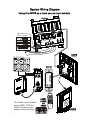
System Wiring Diagram
Using the A0315 as a local source input module
A0315
(Rear)
A0315
(Front)
u t t n
o
1 4
CAT5
A dio Dis ribu io
M
dule
(
equired)
R
ower
P
(Opt
al)
ion
tuSta
s
S s
emy
t
System
nI
put
Lo
ca
l
Input
o
Z
ne 1
Zo 2
ne
oZ
ne 3 Zo
e 4
n
xpan
ion
E
s
Out t
pu
oc l
L a
rior
P ity
ig l
S na
L
R
E t
r
mi te s
PRO
HA NE
L
C
N
TM
V
IO
IS N
IR
x
T
M
H
A
N
N
E
L
V
C
IS
I
ON
M
o
d
el
P
-
201
4
A0125
P-2014
A0501,
A0502,
OR
A0505
The shuttle control buttons
on the A0501, A0502, &
A0505 remotes can be
used to control the iPod.
Tape Monitor or
Room 2 output
(Optional) IR emitters
Sat radio
DVD player
CD player
Receiver
Amp-Link
Channel Vision
R
L/S
Line Out
TM
C
HA
N
O
NE
L
V
I
S
I
N
S
O
U
R
C
E
Z N
O E
POWER
T
MU
E
VOL
1
2
3
4
O
M
DEL
A0501
WER
PO
Source
C
HANNE L
V
ISI ON
Pwr

5
System Wiring Diagram
Using the A0315 as a main source input module
A0315
(Rear)
Amp -Link
Channel Vis io n
R
L/S
Lin e Out
Amp -Link
Channel Vis io n
R
L/S
Lin e Out
Amp -Link
Channel Vis io n
R
L/S
Lin e Out
1 4
A
T5 udi
i b M dul
C A o D
stri
ution o e
(Re uir dq
e )
P w
r
o
e
(O tio
a
p
n
l)
S statu
ys
em
S
t
System
Input
Lo
cal
In
pu
t
Z
ne 1o
Z
ne
2o
Z ne
3
o
Zone 4
E p
n io
x
a
s
n
Outp
tu
Loc
l
a
Prior ity
S
g l
i na
L R
Emitt
r
e s
PRO
H
N E
C
A
N
L
TM
V
I
SI
ON
IR
x
T
M
A N
L
C
H
N
E
V
I
S
I
ON
e 1
4M
o
d
l
P-
20
A0301 and A0315 can be used as primary system inputs feeding the main
hub or as local input modules in each room to override the primary audio
source. The A0301 is a generic input module which provides a standard
®
L/R RCA input and the A0315 is an iPod docking station.
These local input modules should be installed in the CAT5 line between
the P-2014 and the A0125. Multiple input modules can be installed in one
CAT5 run. If audio is present at more than one input module the unit
closest to A0125 will take priority and be played through the speakers.
In this configuration, either the satellite
radio tuner or the A0315 connected to the
System Input of the P-2014 can act as the
main system input. If audio is present from
both sources, then the Priority switch will
determine which source is heard. In this
example the switch is set to give the A0313
priority.
Sour ce
C
HANNEL
V
IS ION
Pwr
Sour ce
C
HANNEL
V
IS ION
Pwr
Room 1 Room 3
A0313A0313
P-2014
A0313 or A0301
(Rear)
A0125
(Rear)
A0302
OUT
OUT
IN
I
N
Secondary audio source
Primary audio source
(See A0125 manual for connection details)
Sat radio

6
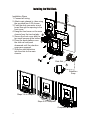
Installing the Wall Dock
Installation Steps
1. Connect all wiring.
2. Attach main chassis to j-box using
the provided four 6-32 screws.
3. Feed the dock connector circuit
board through the opening in the
front cover.
4. Hang the front cover on the main
chassis from the two top tabs.
5. Secure the front cover with the
two small screws at the bottom.
6. Place the dock platform over
the slide rail and push
downward until the retention
snaps are engaged.
7. Slide the side protectors
into the slots on the main
chassis.
Retention
Snap
Slide Rail
2
2
4
3
3
5
6
6
7
5
2
1
Completed Installation
Steps 3 & 4 complete
Steps 5 & 6 complete

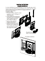
Installing the Wall Dock
(3-gang Installation)
In some installations it may be desirable to mount a single gang control
keypad next to the A0315. To accomplish this, the single gang trim plate
can be installed next to the A0315 in a 3-gang junction box.
Follow the steps below:
4
3
Completed Installation
7
See attachment
detail on previous page
Installation Steps
1. Connect all wiring. Use the correct
installation tools: J-110 tool, or
1014 crimp tool.
2. Install keypad and single-gang
trim plate in the far left position
of the 3-gang junction box.
(See details on page 3)
3. Leave off the right side
flange and trim piece.
4. Install the iPod dock in the
left side of the 3-gang j-box.
It will overlap and snap into
the single gang trim plate.
(See page 5 for details)

CH A NN EL VI SI ON
S
O
U
R
C
E
ZONE
POWER
MUTE
4
3
2
1
CAMERA
CATV
MOD
VOL
1
2
3
4
MODEL
A0505
POWER
Hex codes for IR commands:
iBus Play/Pause:
0000 006D 0000 000B 001F 001F 001F 001F 003F 003F 001F 001F 001F 001F 001F
001F 003F 001F 001F 001F 001F 003F 003F 003F 001F 0CA2
iBus Skip <<:
0000 006D 0000 000B 001F 001F 003F 001F 001F 003F 001F 001F 001F 001F 001F
001F 003F 001F 001F 003F 001F 001F 003F 003F 001F 0CA2
iBus Skip >>:
0000 006D 0000 000A 001F 001F 001F 001F 003F 003F 001F 001F 001F 001F 001F
001F 003F 003F 003F 001F 001F 003F 003F 0CC3
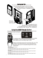
Using the A0505 Remote Control
The buttons above the iBus label on the A0505 remote control will mimic
the functions on the iPod wheel.
The volume, mute, power, and source buttons on the A0505
are designed to control Channel Vision’s whole-house
audio systems such as the A4603 and P-2044.
Please note that this remote will only function when your iPod
is docked in the A0315 wall dock. It must be pointed at an
IR receiver that is part of an amplified keypad that is wired
“downstream”.
Docking the iPod
The dock platform can slide up to hide the dock
connector when the system is not in use. Make
sure the dock platform is in the down position
so the dock connector is exposed (as shown
here).
The sliding dock lever
beneath the dock adjusts the position
of the dock connector to create a perfect fit for
all compatible iPods (see pg. 3 for compatibility).
Slide down
to expose
dock connector
8
TM
By CHANNEL V ISION
G
n
d
2
4
V

C
N
SI
N
HAN
EL
V
I
O
S
O
U
R
C
E
ZO
NE
E
PO
W
R
U
M
TE
4
3
2
1
M
E
CA
RA
TV
CA
M
O
D
VO
L
1
2
3
4
M
L
ODE
A05
05
WPO
ER
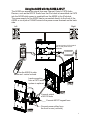
Using the A0315 with the A0350 & A0127
9
The A0350 can accept the signal from one Channel Vision’s CAT5 Audio
Devices, such as the A0315. Audio from the iPod dock is transmitted via CAT5
into the A0350 while power is supplied from the A0350 to the iPod dock.
The power supply for the A0350 can be connected directly to the front of the
A0350 or via a pair of 16AWG wires to the power screw terminals on the back
side.
A0127
A0350
Pwr
Mute
Vid 1
Vid 2
Vid 3
Vid 4
Vol
+
Vol
-
TM
By CHANNEL VISION
TM
By CHANNEL V ISION
A r i a
Local In
Active
Spkrs
24VDCIR In
Flush Mount Amplifier
Left
Right
Use the A0505 to skip
tracks and control volume.
Connect power either from
the front or rear (not both)
Connect output
of A0315 here
A0315
(Rear)
A0350
(Side)
A0315
(Front)
Connect A0127 keypad here
Input connection
from a CAT5 audio
system is optional.
Connect power via front panel
jack or rear panel screw
terminals.
I
R
K
e
y
p
a
d
C
A
T
5
Aud
i
o
R
+
-
L
+
-
G
n
d
G
n
d
2
4
V
2
4
V

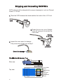
Stripping and Connecting CAT5 Wire
Blade
Cat5
1. Place the CAT5 between the blade and the first notch of the J-110 tool.
CAT5 cable should be stripped with a proper stripping tool, such as Channel
Vision’s J-110 tool.
Slight
pressure
Rotate
1 turn only
2. Rotate the tool only once. Multiple
turns will cause you to cut into the
inner wires.
3. Inspect the inner wires for damage.
If any wires are cut start over at step 1.
Check for damage
Green/White
Green
Orange/White
Blue
Blue/White
Orange
Brown/White
Brown
TIA-568A RJ-45 Modular Plug
Side view:
Top view:
10

1) Be sure you have connected the CAT5 cable correctly. Follow the
TIA-568A standard at both ends. Incorrect wiring can cause distorted
sound or prevent the system from working at all!
2) Be sure you have connected the speakers in phase. Follow the label
on the product. Out of phase speakers can rob the system of its
bass. Especially when driving dual-voice-coil speakers.
3) Trouble with IR control?
a. Make sure you are using the correct remote control. The A0315 will
only respond to IR signals from the Apple Remote produced by Apple
Computer or the A0505 produced by Channel Vision. Other 3rd party
remote controls are not supported.
b. Check the batteries in the remote control and change them if
necessary.
4) The A0315 is designed to charge the iPod
(see compatibility notes on
page3)
. When the iPod is not playing music, the screen should
indicate that the iPod is being charged. If this does not occur, make
sure the power is reaching the volume control keypad (press the
volume buttons to see if the LED indicators light up).
5) Observe wiring distance specifications. The maximum
recommended wire length between the wall dock and CAT5 audio
hub is 250 feet. Although the A0315 may work at greater distances,
extreme distances are not recommended because erratic
performance may result due to the power loss caused by the CAT5
wire.
6) If you are experiencing problems with your iPod that occur even
when it is not docked in the A0315, then please contact Apple
customer service for support.
7) If you need additional help troubleshooting the A0315 please contact
Channel Vision technical support or check our website for more
details: www.channelvision.com.
Connection Tips and Troubleshooting
11

Channel Vision Technology will repair or replace any defect in material or workmanship
which occurs during normal use of this product with new or rebuilt parts, free of charge in
the USA, for two years from the date of original purchase. This is a no hassle warranty with
no mail in warranty card needed. This warranty does not cover damages in shipment,
failures caused by other products not supplied by Channel Vision Technology, or failures
due to accident, misuse, abuse, or alteration of the equipment. This warranty is extended
only to the original purchaser, and a purchase receipt, invoice, or other proof of original
purchase date will be required before warranty repairs are provided.
Mail in service can be obtained during the warranty period by calling (800) 840-0288 toll
free.A ReturnAuthorization number must be obtained in advance and can be marked on the
outside of the shipping carton.
This warranty gives you specific legal rights and you may have other rights (which vary
from state to state). If a problem with this product develops during or after the warranty
period, please contact Channel Vision Technology, your dealer or any factory-authorized
service center.
Channel Vision products are not intended for use in medical, lifesaving, life sustaining or
critical environment applications. Channel Vision customers using or selling Channel
Vision products for use in such applications do so at their own risk and agree to fully
indemnify Channel Vision for any damages resulting from such improper use or sale.
500-282 revB
This device complies with part 15 of the FCC rules. Operation is subject to the following
two conditions: (1) This device may not cause harmful interference, and (2) This device
must accept any interference received, including interference that may cause undesired
operation.
Tes te d To C o mp ly
With FCC Standards
Model: A0315
iPod Wall Dock for Distributed Audio
www.channelvision.com
234 Fischer Avenue, Costa Mesa, California 92626 USA
(714)424-6500 (800)840-0288 (714)424-6510 fax
email: [email protected]
iPod is a trademark of Apple, Inc., registered in the U.S. and other countries.
Specifications: (typical @25º C)
Operating Voltage : 18VDC
Cable Requirements: CAT-5 or better
Operating Temperature: -10ºC to +50ºC
Specifications subject to change without notice.
1
-
 1
1
-
 2
2
-
 3
3
-
 4
4
-
 5
5
-
 6
6
-
 7
7
-
 8
8
-
 9
9
-
 10
10
-
 11
11
-
 12
12


Channel Vision IBUS A0315 Instructions Manual
- Categoria
- Altoparlanti docking
- Tipo
- Instructions Manual
in altre lingue
- English: Channel Vision IBUS A0315
Documenti correlati
Altri documenti
-
Eurotherm 4181/4250 Chart Recorders Serial Comms Manuale del proprietario
-
Hitachi PLC Getting Started
-
AVENTICS Module de bus BDC, B-Design, CANopen et CANopen sb Manuale del proprietario
-
Socomec DIRIS A-30/A-41 Istruzioni per l'uso
-
-
-
-