CONSEILS ET SUGGESTIONS
15
CONSEILS ET SUGGESTIONS
La présente notice d’emploi vaut pour plusieurs versions de l’appareil. Elle
peut contenir des descriptions d’accessoires ne figurant pas dans votre ap-
pareil.
INSTALLATION
• Lefabricantdéclinetouteresponsabilitéencasdedommagedûàuneinstal-
lationnoncorrecteounonconformeauxrèglesdel’art.
• Ladistanceminimaledesécuritéentreleplandecuissonetlahottedoitêtre
de650mmaumoins(certainsmodèlespeuventêtreinstallésàunehauteur
inférieure : se reporter aux paragraphes « Encombrement » et « Installation »).
• Vérifierquelatensiondusecteurcorrespondàlavaleurquifiguresurlapla-
quette apposée à l’intérieur de la hotte.
• PourlesAppareilsappartenantàlaIèreClasse,veilleràcequelamiseàlaterre
de l’installation électrique domestique ait été effectuée conformément aux
normes en vigueur.
• Connecterlahotteàlasortied’airaspiréàl’aided’unetuyauteried’undiamè-
treégalousupérieurà120mm.Leparcoursdelatuyauteriedoitêtreleplus
court possible.
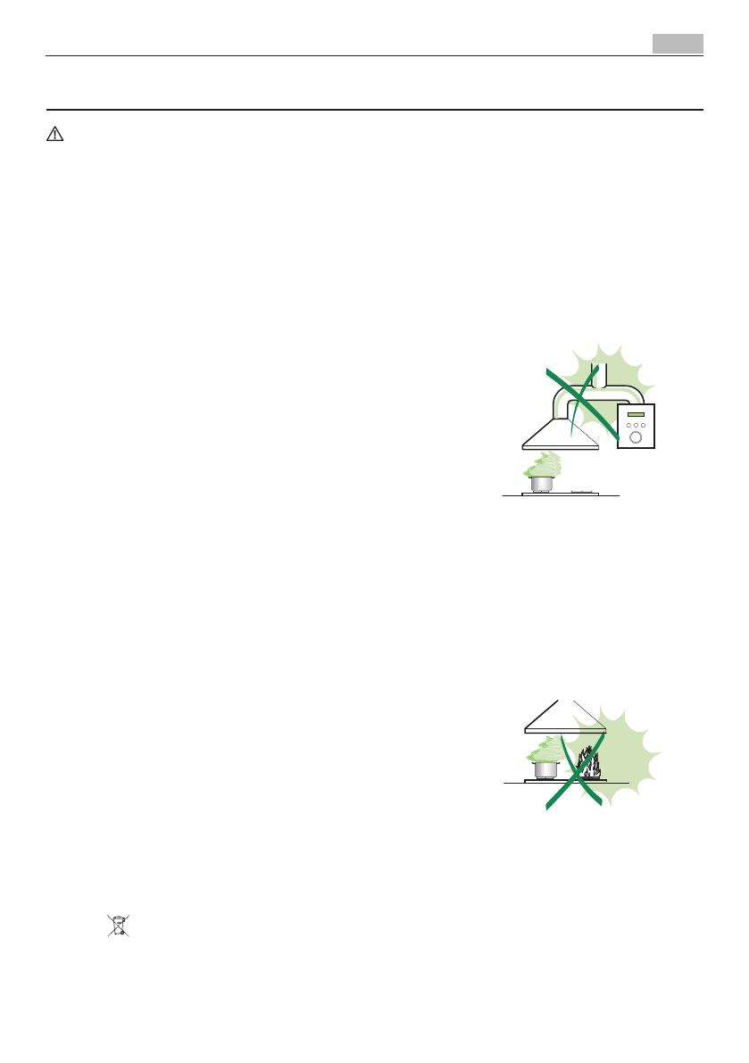
• Eviterdeconnecterlahotteàdesconduitesd’évacuationdefuméesissues
d’unecombustiontelque(Chaudière,cheminée,etc…).
• Sivousutilisezdesappareilsquinefonctionnentpasàl’électricitédansla
pièceouestinstalléelahotte(parexemple:desappareilsfonctionnantau
gaz),vous devez prévoir uneaérationsuffisantedumilieu. Si lacuisine en
estdépourvue,pratiquezuneouverturequicommuniqueavecl’extérieurpour
garantir l’infiltration de l’air pur.
UTILISATION
• Lahotteaétéconçueexclusivementpourl’usagedomestique,danslebut
d’éliminer les odeurs de la cuisine.
• Nejamaisutiliserabusivementlahotte.
• Nepaslaisserlesflammeslibresàforteintensitéquandlahotteestenser-
vice.
• Toujoursréglerlesflammesdemanièreàévitertoutesortielatéraledeces
dernièresparrapportaufonddesmarmites.
• Contrôlerlesfriteuseslorsdel’utilisationcarl’huilesurchaufféepourraits’en-
flammer.
• Nepaspréparerd’alimentsflambéssouslahottedecuisine:risqued’incen-
die
• Cetappareilnedoitpasêtreutilisépardespersonnes(ycomprislesenfants)
ayant des capacités psychiques, sensorielles ou mentales réduites, ni par des
personnes n’ayant pas l’expérience et la connaissance de ce type d’appareils,
àmoinsd’êtresouslecontrôleetlaformationdepersonnesresponsablesde
leur sécurité.
• Les enfants doivent êtresurveilléspour s’assurerqu’ilsnejouentpasavec
l'appareil.
ENTRETIEN
• Avantdeprocéderàtouteopérationd’entretien,retirerlahotteenretirantla
fiche ou en actionnant l’interrupteur général.
• Effectuer un entretien scrupuleux et en temps dû des Filtres,à la cadence
conseillée (Risque d’incendie).
• Pourlenettoyagedessurfacesdelahotte,ilsuffitd’utiliserunchiffonhumide
et détersif liquide neutre.
Le symbole surleproduitousonemballageindiquequeceproduitnepeutêtretraitécommedéchetménager.Ildoitplutôtêtre
remis au point de ramassage concerné, se chargeant du recyclage du matériel électrique et électronique. En vous assurant que ce produit
estéliminécorrectement,vousfavorisezlapréventiondesconséquencesnégativespourl’environnementetlasantéhumainequi,sinon,
seraientlerésultatd’untraitementinappropriédesdéchetsdeceproduit.Pourobtenirplusdedétailssurlerecyclagedeceproduit,veuillez
prendrecontactaveclebureaumunicipaldevotrerégion,votreserviced’éliminationdesdéchetsménagersoulemagasinoùvousavez
acheté le produit.


