
2900/260 LF
2900/260 LFC
Monochrome and Color Terminals
User’s Guide
598-0011412

Before using this information and the product it supports, be sure to read the general information under “Notices.”
It is the policy of Boundless Technologies, Inc. to improve products as new technology, components, software, and firmware
become available. Boundless Technologies, therefore, reserves the right to change specifications without prior notice.
All features, functions, and operations described herein may not be mar
keted by Boundless Technologies in all parts of the world.
In some instances, photographs are of equipment prototypes. Therefore, before using this document, consult your Boundless
Technologies representative or Boundless Technologies office for information that is applicable and current.
Note that Boundless Technologies appreciates re
ceiving suggestions and comments on its publications. After reading this guide,
please comment and return the comment sheet that has been provided.
Copyright © Boundless Technologies, Inc. 2007-2009. Phelps, New York
All rights reserved.

This guide...
is a user’s manual and contains all of the information necessary to install, setup, and use the 4000/260 LF
product.
More detailed information on programming using control codes and escape sequences, default strings and
character s
ets, international language support, etc. can be obtained by calling the Boundless Technologies Hotline at:
USA and Canada calls . . . . 1-800-231-5445
International calls . . . . . . . 1-315-548-6189
Request the following:
260xx Programmer’s Reference Guide
Part Number: 598-0005035
OR visit http://support.boundless.com to download the guide.
This manual is offered to our customers at no additional charge. When calling to order, please have your
terminal’s serial number available.

Contents i
Contents
Preface iii
How to Connect/Disconnect the Terminal .............................iv
Notices.................................................................................iv
Trademarks and Service Marks ............................................. v
Electronic Emission Notices .................................................. v
Safety Notices ......................................................................vi
Introduction 7
Features............................................................................... 2
Vertical Mount: ...........................................................................3
Under-Desk Mount: .....................................................................3
Wall Mount:.................................................................................4
Physical Features ................................................................. 5
Keyboards ............................................................................ 6
Display Fields ....................................................................... 7
Usage Notes ......................................................................... 8
Communications................................................................... 9
Receive Flow Control..................................................................9
Transmit Flow Control ...............................................................9
Host/Printer Port 1 (DB25) ........................................................9
Host/Printer Port 1 (RJ45).......................................................10
Video Port (DB15) .....................................................................10
Keyboard Ports (Mini-din or RJ11)...........................................10
Host/Printer Port 2 ..................................................................11
Parallel Printer Port.................................................................. 11
Terminal To Modem (or DCE Host) ..........................................12
Screen Display And Pages................................................... 13
Bottom Status/Label Line Display ...........................................13
Visual Effects Of Screen And Page Lengths .............................14
Installation 15
Step 1 - Physical Connections ............................................. 15
Step 2 - Number Of Sessions............................................... 15
Step 3 - Link Ports To Sessions ........................................... 15
Step 4 - No Printer Option................................................... 16
Step 5 - Determine Your Serial Port(s) Protocol.................. 16
Step 6 - Alternate Input Data Setup Selection..................... 16
Step 7 - Host/Printer Setup Selection ................................. 16
Step 8 - Modem Control Setup Selection ............................. 16
Step 9 - Communications Protocol Settings......................... 16
Connection A - DTE Host On EIA .............................................16
Connection B - DTE Host On Aux.............................................17
Connection C - DCE Host/Modem On EIA ...............................17
Connection D - DCE Host/Modem On Aux...............................17
Connection E - Serial Printer On EIA.......................................17
Connection F - Serial Printer On Aux ......................................17
Connections G & H - Serial Or Parallel Printer On Parallel .....17
Step 10 - Emulation Setup Selection ................................... 17
Step 11 - Additional Setup Options ..................................... 17
Step 12 - Save Parameters.................................................. 18
Step 13 - Establish Communications ................................... 18
Host/Printer Connection Guide ........................................... 19
Common Setups.................................................................. 21
User Settings...................................................................... 22
Setup 23
Overview............................................................................ 23

Contents ii
Entry And Exit..................................................................... 23
Printing .............................................................................. 23
Saving Parameters ............................................................. 23
Movement Inside Menus..................................................... 24
Action Fields....................................................................... 24
Dual Session Mode.............................................................. 24
Setup Map .......................................................................... 25
Quick: F1............................................................................ 27
General: F2......................................................................... 28
Display: F3 ......................................................................... 29
Keyboard: F4 ...................................................................... 30
Keys: F5 ............................................................................. 31
Ports: F6............................................................................. 33
Host: F7.............................................................................. 33
Print: F8 ............................................................................. 34
Emulation: F9 ..................................................................... 34
ASCII Emulations......................................................................34
ANSI Emulations.......................................................................35
Tabs: F10............................................................................ 36
Answerback: F11 ................................................................ 36
Program: F12...................................................................... 37
Execute: Prt Sc ................................................................... 38
Edit Fields........................................................................... 38
Glossary of Terms............................................................... 39
Page Reset................................................................................. 39
Terminal Parameters ................................................................39
Session Parameters...................................................................39
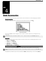
Desk Accessories 40
Desk Accessory Menu ...............................................................40
Direct Entry ..............................................................................40
Exiting A Desk Accessory .........................................................41
Inhibiting Access ......................................................................41
Calendar............................................................................. 41
Clock .................................................................................. 42
Calculator........................................................................... 43
ASCII Chart ........................................................................ 44
Diagnostic Menu................................................................. 44
Color Utility ........................................................................ 45
Compose 46
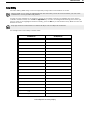
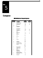
ANSI-Multinational Compose Sequences............................. 46
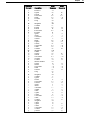
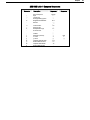
ANSI-ISO Latin-1 Compose Sequences ............................... 48
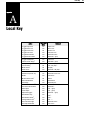
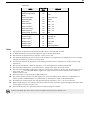
Local Key 49
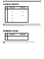
Page Configurations - Single Host Mode.............................. 51
Page Configurations - Dual Host Mode ................................ 51
Note To Installer 52
Technical Support 52

How to Connect/Disconnect the Terminal iii
Preface
This product is in conformity with the protection requirements of EU Council Directive 89/336/EEC on the
approximation of the laws of the Member States relating to electromagnetic compatibility.
Boundless Technologies cannot accept responsibility for any failure to satisfy the protection requirements
resulting fro
m a non-recommended modification of the product, including the fitting of non- Boundless
Technologies option cards.
This product had been tested and found to comply with the limits for Class B Information Technology Equipment
according to CI
SPR 22/European Standards EN 55022. The limits for Class B equipment were derived for
typical environments to provide reasonable protection against interference with licensed communication devices.

How to Connect/Disconnect the Terminal iv
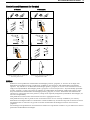
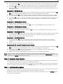
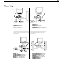
How to Connect/Disconnect the Terminal
To Connect: To Disconnect:
First, turn everything OFF.
First, turn everything OFF.
Attach all cables to devices.
Remove power cord from outlet.
Attach signal cables to receptacles.
Remove signal cables from receptacles.
Attach power cord to outlet.
Remove all cables from devices.
Turn device ON.
You may now take it with you.
Note: In the UK, by law, the
telephone cable must be connected
after the power cord.
Note: In the UK, by law, the power
cord must be disconnected after the
telephone line cable.
Notices
References in this publication to Boundless Technologies products, programs, or services do not imply that
Boundless Technologies intends to make these available to all countries in which Boundless Technologies
operates. Any reference to an Boundless Technologies product, program, or service is not intended to state or
imply that only Boundless Technologies product, program, or service may be used. Any functionally equivalent
product, program, or service that does not infringe any of Boundless Technologies’ intellectual property rights
may be used instead of Boundless Technologies product, program, or service. Evaluation and verification of
operation in conjunction with other products, except those expressly designated by Boundless Technologies, are
the user’s responsibility.
This publication could contain technical inaccuracies or typographical errors.
This publication may refer to products that are announced but are not currently available in your country.
Boundle
ss T
echnologies makes no commitment to make available any unannounced products referred to herein.
The final decision to announce any product is based on Boundless Technologies’ business and technical
judgment.
The drawings and specifications contained herein shall not be reproduced in whole or in part without the written
permission of
Boundless Technologies.

Trademarks and Service Marks v
Trademarks and Service Marks
The following terms are trademarks of these companies:
ADDS Viewpoint Boundless Technologies, Inc.
Centronics Cen
tronics Data Computer Corporation
CSA Canadian Stan
dards Association
DEC VT320/220/100 Digital
Equipment Corporation
IBM International Busi
ness Machines Corporation
MENTOR Boundless Te
chnologies, Inc.
SCO Santa Cruz O
perations, Inc.
TVI 925 Tele
Video Systems, Inc.
UL Un
derwriters Laboratories Inc.
WYSE Wyse Tech
nology Inc.
WYSE 50/50+/60/120/150 Wyse Technology Inc.
Electronic Emission Notices
Federal Communication Commission (FCC) Statement
Note: This equipment has been tested and found to comply with the limits for a Class A digital device, pursuant
to Part 15 of the FCC Rules. These limits are designed to provide reasonable protection against harmful
interference when the equipment is operated in a commercial environment. This equipment generates, uses,
and can radiate radio frequency energy and, if not installed and used in accordance with the instruction
manual, may cause harmful interference to radio communications. Operation of this equipment in a residential
area is likely to cause harmful interference, in which case the user will be required to correct the interference at
his own expense.
Properly shielded and grounded cables and connectors must be used in order to meet FCC emission limits.
Boundle
ss T
echnologies is not responsible for any radio or television interference caused by using other than
recommended cables and connectors or by unauthorized changes or modifications to this equipment.
Unauthorized changes or modifications could void the user's authority to operate the equipment.
This device complies with Part 15 or the FCC Rules. Operation is subject to the following two conditions: (1) this
devic
e may not cause harmful interference, and (2) this device must accept any interference received, including
interference that may cause undesired operation.
Canadian Department of Communications Compliance Statement
This equipment does not exceed Class A limits per radio noise emissions for digital apparatus, set out in the
Radio Interference Regulation of the Canadian Department of Communications.
Avis de conformité aux normes du ministère des Communications du Canada
Cet équipement ne dépasse pas les limites de Classe A d'émission de bruits radioélectriques pour les appareils
numériques, telles que prescrites par le Règlement sur le brouillage radioélectrique établi par le ministère des
Communications du Canada.
Japanese Voluntary Control Council for Interference (VCCI) Statement
This equipment is Class 1 Equipment (information equipment to be used in commercial and industrial districts)
which is in conformance with the standard set by Voluntary Control for Interference by Data Processing
Equipment and Electronic Office Machines (VCCI) with an aim to prevent radio interference in commercial and
industrial districts.
This equipment could cause interference to radio and television receivers when used in and around residential
districts.
Please handle the equipment properly according to the instruction manual.
Korean Government Ministry of Communication (MOC) Statement
Please note that this device has been approved for business purposes with regard to electromagnetic
interference. If you find this is not suitable for your use, you may exchange it for a non-business purpose one.

TSafety Notices vi
Safety Notices
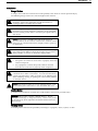
Danger Notices
A danger notice indicates a hazard that could possibly cause death or serious personal injury.
The following danger notices are used throughout this manual.
DANGER: To prevent a possible electrical shock when installing
the device, ensure that the power cord for that device is
unplugged before installing signal cables.
DANGER: To prevent a possible electrical shock when adding
the device to a system, disconnect all power cords, if possible,
from the existing system before connecting the signal cable to
that device.
DANGER: To prevent a possible electrical shock during an
electrical storm, do not connect or disconnect cables or station
protectors for communication lines, display stations, printers,
or telephones.
DANGER: To prevent a possible electrical shock from touching
two surfaces with different electrical grounds, use one hand,
when possible, to connect or disconnect signal cables.
DANGER: To avoid a shock hazard:
The power cord must be connected to a properly wired and
e
arthed receptacle.
Any equipment to which this product will be attached
must also be connected to properly wired receptacles.
DANGER: Electrical current from power, telephone, and
communication cables is hazardous. To avoid shock hazard,
connect and disconnect cables as shown on the following page
when installing, moving, or opening the covers of this product
or attached devices.
DANGER: The device’s switch is not the main disconnect. The
device’s main power disconnect is the detachable line cord.
Caution Notice
A caution notice indicates a hazard that could possible cause minor personal injury.
CAUTION: T
his product contains a lithium battery. Do not
attempt to exchange or charge the battery. Discard the product
as instructed by local regulations for limited lithium batteries.
Do not burn.
Warning Notice
A warning notice indicates the possibility of damage to a program, device, system, or data.

TSafety Notices vii
ch
apter
1
Introduction
This guide contains information on all areas of the 260lf product. However, not all 260lf terminals are equipped
with all the features in this publication (i.e. the descriptions of color features do not apply to the monochrome
product).
The terminal you have purchased features a small footprint logic controller and a VGA monitor, while providing
support for both ASCI
I and ANSI terminals, PC-Term and SCO™ Console and AT386. PC 101/102-key keyboard
is available for use with the terminal, as well as Compact PC 101-key keyboard.
The dual host capability of the terminal allows you to run two different applications simultaneously. A Setup
option is available to vi
ew each “session” on the screen in a “split” screen or full screen display.
Clock, calendar, calculator, ASCII chart, and diagnostic desk accessories are provided.
For the 260lfc, Color Desk Accessory is available.
The highlighted text shown above is used to identify features that are only available in 260lfc unit.
This terminal also features an easy-to-use Setup menu that is configuration dependent; this means that only the
options that are valid for a
given emulation or hardware configuration are presented.
Setup also has a “Quick” menu that summarizes all the options critical to the operation of the terminal. Travel
between menus is facilitated by function keys that are listed at the top of every menu.

2
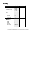
Features
Personality:
• ADDS-Viewpoint™ (ASCII emulation)
• Wyse™60, Wyse 50/50+ (ASCII emulation)
• DEC™ VT-320, VT-220, VT-100 (ANSI Emulation)
• PC Terminal (PC Term)
• SCO-Console (ANSI Emulation)
• AT386 (ANSI Emulation)
• TVI925 (ASCII emulation)
• Intercolor (ANSI Emulation)
• Wyse 325, Wyse 350 (ASCII emulation)
Display:
• Dual session available in full or split screens
• VGA monitor (Color or Monochrome).
• Selectable Screen Saver
• 26, 44, or 49 Row Display with Top and Bottom Status Lines
• 80 or 132 Column Display
• Double High/Double Wide Display
• Up to 4 Pages of Memory
Character S
ets:
• Support for 17 different language character sets: US, UK, Danish, Finnish, French, German, Norwegian,
Portuguese, Spanish, Swedish, Dutch, Belgian-Flemish, French-Canadian, Italian, Latin-American,
Swiss- French, Swiss-German
• Numerous Standard, Graphic, and Supplemental Character Sets
Communications:
• Serial RS-232-C Host/Printer Port 1 (DB25 or RJ45 connector) operating from 110 to 115,200 baud
• Serial RS-232-C Host/Printer Port 2 (RJ45 connector) operating from 110 to 38,400 baud
• Parallel IBM™/Centronics™ compatible printer port
Keyboards:
• PC 101/102-key keyboard (RJ11 connector, standard)
• Compact PC 101-key keyboard (mini-din connector) available
• ANSI keyboard
• Up to 28 shiftable and programmable edit and function keys
Desk Accessories:
• Calculator capable of transmitting results
• Monthly Calendar
• Clock with alarm settings
• ASCII and Diagnostic charts
• Color Desk Accessory

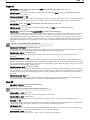
3
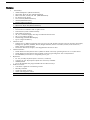
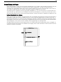
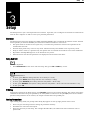
Vertical Mount:
1. Insert the tabs into the corresponding slots as shown (left).
2. While applying pressure on the bracket, slide the bracket toward the front of the of
logic unit until it clicks into place
.
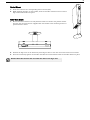
Under-Desk Mount:
1. Ensure that the bracket is securely fastened under the desk in the position shown.
You may use the wood screws supplied with the bracket if the mounting surface is
particle board or wood.
2. Position the
l
ogic unit on the bracket by directing the slots in the unit around the tabs on the bracket.
3. Press the unit firmly against the bracket and slide the unit backward until the bracket clicks into place.
Double check that all four tabs are inside the slots in the logic unit.

4
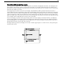
Wall Mount:
1. Ensure that the bracket is securely fastened to the wall in the position shown. You may use the wood screws
supplied with the bracket if the mounting surface is particle board or wood.
2. Position the logic unit on the bracket by directing the slots in the unit around the tabs on the bracket.
3. While pressing the logic unit towards the wall, slide the unit downwards until it clicks into place.
To order the Mounting Bracket, please quote part number 598-0005109

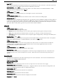
5
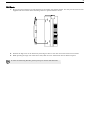
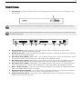
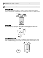
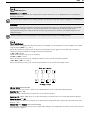
Physical Features
1. Power Switch - pre
ss the orange button to its recessed position to turn the unit “on.” Press again to turn
the unit “off.”
Leave the terminal’s power switch (1) in the off position “0" until power and keyboard connections are made
The Canadian Standards Association (CSA) recommends that the power outlet be near the terminal and easily
accessible at all times.
2. Power Connection - plug the power cord into this connector and the wall-mount or other remote
transformer into a properly grounded receptacle.
3. Parallel Printer Port - connect the cable from the IBM or Centronics compatible parallel printer to this port.
See Chapter 2 for installation options.
4. Host/Printer Port 2 (RJ45) - labeled “Aux” - with an RJ45 connector only, connect the cable from a second
host (dual host mode) or serial printer here. See Chapter 2 for installation options.
5. Host/Printer Port 1 (RJ45) - labeled “EIA” - with a RJ45 connector only, connect the cable from the first
host or serial printer here. Connect only one EIA port at a time. See Chapter 2 for installation options.
6. Host/Printer Port 1 (DB25) - labeled “EIA” - with a DB25 connector only, connect the cable from the first
host or serial printer here. Connect only one EIA port at a time. See Chapter 2 for installation options.
7. Video - Output to monitor - attach the
connector from the monitor here. The port is a DB15 female which
means that a DB15 male connector is required.
8. Keyboard Connector (mini-din) - on a Compact PC 101-key keyboard only, line up the notch and pins of
the mini-din connector and push in here. Connect only one keyboard at a time.
9. Keyboard Connector (RJ11) - on a PC(101/102) or ANSI keyboard, push in the keyboard connector here.
Connect only one keyboard at a time.

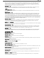
6
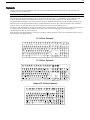
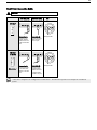
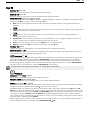
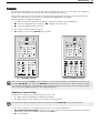
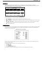
Keyboards
The monochrome terminal supports only the “PC-style” keyboards which include the PC 101/102-key and
Compact PC 101-key keyboard.
The color terminal supports two styles of keyboards: “PC-style” and “ANSI-style” keyboards.
The keyboard layout is divided into functional key groups (as described below). The ANSI - style keyboard differs
from the PC-style keyboard mainly in that it features 20 function keys, a set of PF-keys, and a different style
numeric keypad. The PC-style keyboards include the PC 101-key and Compact PC 101-key keyboards.
The alphanumeric keypad is the main typewriter keypad, while the function key group lies along the top of the
keyboard and
can be programmed locally or downloaded from the host. The numeric keypad is the calculator-
style set of keys on the right hand side of the keyboard, used in entering numeric data.
The cursor and edit keypads, located to the left of the numeric keypad. The function key group is located above
the alphanu
meric keypad. The communication key group, above the edit keypad, is used to control
communications with the host or printer.
Each keyboard is equipped with a set of local “hot-keys”, which perform a variety of terminal functions, such as
“Print Screen
” and “Enter Setup”
PC 101-key Keyboard
SysR q Break
Pause
Inse rt
Delete End
7 8 9
+
4 5 6
1 2 3
Enter
Del
.
0
Ins
-
*
/
Print
Scrn
Scroll
Lock
Home
Page
Up
Page
Down
Num
Lock
End
Home PgUp
PgDn
@
2
$
4
!
1
6
&
7
8
=
3
%
5
(
9
)
0
Q W E R T Y U I O P
[
F
D
SA
G H J
"
LK
X C V B MN
.
/
Z
Ctrl
Ctrl
Alt
Alt
Esc
F4F3F2F1
+
{}
_
-
Caps
Lock
?
*
^
><
:
;
]
'
~
#
,
Shift Shift
Tab
F12F11F10F9F8F7F6F5
Num
Lock
Caps
Lock
Scroll
Lock
Back
Space
|
\
Enter
+
PC 102-key Keyboard
Compact PC 101-key Keyboard

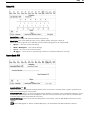
7
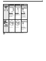
ANSI Keyboard
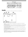
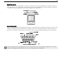
Display Fields
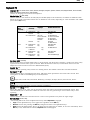
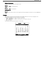
The screen display shown below is a snapshot of the terminal’s screen in an ASCII emulation.
The top line of the display is referred to as the T
op Status Line. The Top Status Line can be disabled if
desired.
The bottom line of the display can serve as a Bottom Status Line in ANSI emulations or a Function Key Label
Line for ASCII emulations.
The Sess
ion Indicator displays the number of the session whose data is displayed below the Top Status Line.
The Pa
ge # indicator displays the page number of the currently displayed page (except for page 0, when
nothing is displayed in this field).
The Monitor Mode field indicator will be present only if “Monitor Mode” is set to On (either through Setup or
manually from the keyboard).
The Communication field will display FDX, HDX, BLK, or LOC to represent the current communication mode
for the session indicated by the Session Indicator.
The C
ursor Position indicator displays the position of the cursor in row and column numbers separated by a
colon (e.g. 5:22).
The Self-test Result field indicates the results (Pass or Check) of the self-diagnostic tests performed by the
terminal at startup. This field is cleared with the first keystroke after power up. If the Check message
appears, turn the terminal off and on. If the message still appears, call the technical support number listed
inside of the front cover of this guide.

8
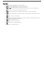
Usage Notes
The following notations and symbols are used in this manual:
Ctrl-F1: the two keys, Ctrl and F1, are to be pressed simultaneously.
Ctrl, F1: the two keys, Ctrl and F1, are to be pressed in succession.
1-num or 1-alph: specifies that the number must be generated either from the numeric or alphanumeric
keypads.
23h: the number 23 is represented in hexadecimal (hex) notation.
applies to ASCII emulations only: ADDS-VP, Wyse 50+, Wyse 60, PC Term, and TVI-925.
applies to ANSI emulations only: VT300/8, VT300/7, VT200/8, VT200/7, VT100, SCO Console, and
AT386.
applies to SCO Console and AT386.
applies to parallel attribute emulations only: includes all emulations except ADDS-VP, TVI 925 and
Wyse 50+ (which are field attribute emulations).
applies to ASCII key mode only.
applies only to Scan Code key mode.
applies to the PC/+ or EPC keyboards only.
applies to the ANSI keyboard only.

9
Communications
This terminal is equipped with three communications ports. The two serial ports are intended for connection to
either a host (or modem), an alternate input device such as a scanner, or a serial printer. (The EIA port has both
an RJ45 and a DB25 interface; either, but not both, can be used.) The last port is a Centronics-compatible
printer port which could be used with a parallel printer or other output device (such as a cash drawer) connected
to a parallel interface. The port you use as the printer port depends on whether you have a serial or a parallel
interface to the printer. Another factor affecting your port selection is whether the terminal is being used in a
single or dual host environment.
Either “EIA” serial port (DB25 or RJ45) can communicate with your computer or printer at a baud rate of 110 to
115,200 baud (bits pe
r s
econd). The second host/printer serial “Aux” port can communicate at speeds from 110
baud to 38,400 baud. Any of these ports can be used to connect to a host computer/modem or serial printer.
Receive Flow Control
Because devices can receive data faster than they can process it, data flow control (selectable in the PORTS
menu of Setup) should be used to prevent data loss. Software flow control relies on the Xon and Xoff characters
(“g” and “e” characters in PC-Term mode) to indicate when the terminal is able or unable to store further data.
The Xon signal transmits the DC1 character (11h) and the Xoff signal transmits DC3 (13h).
This terminal has a receive buffer capable of holding 256 bytes (or characters). When the buffer becomes half full
(128 bytes), a
nd “EIA (or Aux) Rcv” in the Setup menu for PORTS is “Xon-Xoff,” the terminal issues an Xoff
character, indicating to the host that it should stop transmitting data. The terminal will then continue to process
data until its receive buffer holds only 32 bytes. It will then issue an Xon character to the host, indicating that it
can resume sending data to the terminal.
If the “EIA (or Aux) Rcv” is “No Protocol” in Setup, the terminal will continue to accept characters into its
receive buffer until it is full. Additional characters will be lost. Xon-Xoff protocol must also be set on the host
computer or printer for proper handshaking.
In addition to software “receive” flow control (Xon-Xoff), the serial host/printer ports support “receive” hardware
flow control. The EIA ports have an outgoing DTR (Data Terminal Ready) signal. If the DTR signal on the
terminal is low and “EIA Recv” is “DTR” in Setup, then the serial device will stop sending to the terminal. On the
AUX port, the incoming DSR (Data Set Ready) signal serves to signal the device that the terminal is not ready to
receive more data, if “Aux Recv” is “DSR” in Setup.
Transmit Flow Control
Likewise, the terminal will understand the Xon and Xoff requests from the host when it is transmitting data
(provided the “EIA (or Aux) Xmt” is “Xon-Xoff” in Setup). This is referred to as “transmit” flow control.
This terminal will stop transmitting data to the host or printer when it receives an Xoff (DC3) code. If, however,
the terminal needs to send a receive protocol character, it will transmit that character even if it has received an
Xoff code. When the terminal stops transmitting, the data will be buffered in the transmit buffer (64 characters
for the first host/printer port and 64 characters for the second host/printer port).
Once the buffer is full, additional keyboard data will be lost. When an Xon (DC1) character is received, the
terminal can
again send data to the attached serial device.
In addition to software “transmit” flow control (Xon-Xoff), the serial host/printer ports support “transmit”
hardware flow control, whereby DSR on the EIA port and DTR on the AUX port monitor serial devices to control
the flow of data to them (provided EIA and AUX Xmit is “DSR” and “DTR” in Setup).
For parallel printers, this terminal monitors the BUSY and ERROR signals which are sent by the printer to
det
ermine when data transmission should be stopped or resumed.
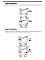
Host/Printer Port 1 (DB25)
This port, labeled “EIA,” located to the left of the video port, is designed for connection to the host (computer or
modem) or a serial printer via a 25-pin D-shell (DB25P) female connector. This port uses an RS-232-C
communication interface, is configured as a DTE (Data Terminal Equipment) device, and can operate from 110 to
115,200 baud. The pins supported are shown below.

10
Refer to the Installation chapter for details on the connection of the DB25 EIA port or the RJ45 EIA port to
serial devices (hosts, modems, or printers).
The optional RS-422 and current loop communications interface is only available for this DB25 EIA port.
Host/Printer Port 1 (RJ45)
This port, labeled “EIA,” located to the right of the “Aux” port, is designed to connect to a host (computer or
modem) or a serial printer and can operate from 110 to 115,200 baud. This port also uses an RS-232-C interface
via an RJ45 female connector and is configured as a DTE device.
Video Port (DB15)
The port labeled “Video” is designed to connect to the VGA monochrome or color monitor. The
interface is a 15-pin, D-shell female connector. The pin assignments for this port are shown below.
Keyboard Ports (Mini-din or RJ11)
There are two keyboard connector ports provided. Only one keyboard should be connected at one time. The PC
101-key and ANSI keyboards will connect to the RJ11 or the mini-din interface, depending on the type of cable
used. The Compact PC 101-key keyboard will connect to the mini-din port.

11
Host/Printer Port 2
This port, labeled “Aux,” is designed to connect to a second host connection (computer or modem), a scanner or
other input device, or a serial printer, and can operate from 110 to 38,400 baud. This port also uses an RS-232-
C interface via an RJ45 female connector and is configured as a DCE device.
Parallel Printer Port
This port, labeled “Parallel” is designed for connection to a parallel printer, which has a Centronics interface with
a 25-pin D-shell female connector. This port, unlike the others, is a uni-directional device, which means that it
only serves to output data to the printer, and cannot receive. The pins and signals supported are shown below.
If you have opted to use a parallel printer, but it is not connected, an error message will appear on the status
line when any PRINT operation is done. To clear the message, press Ctrl-Shift-Tab.
La pagina si sta caricando...
La pagina si sta caricando...
La pagina si sta caricando...
La pagina si sta caricando...
La pagina si sta caricando...
La pagina si sta caricando...
La pagina si sta caricando...
La pagina si sta caricando...
La pagina si sta caricando...
La pagina si sta caricando...
La pagina si sta caricando...
La pagina si sta caricando...
La pagina si sta caricando...
La pagina si sta caricando...
La pagina si sta caricando...
La pagina si sta caricando...
La pagina si sta caricando...
La pagina si sta caricando...
La pagina si sta caricando...
La pagina si sta caricando...
La pagina si sta caricando...
La pagina si sta caricando...
La pagina si sta caricando...
La pagina si sta caricando...
La pagina si sta caricando...
La pagina si sta caricando...
La pagina si sta caricando...
La pagina si sta caricando...
La pagina si sta caricando...
La pagina si sta caricando...
La pagina si sta caricando...
La pagina si sta caricando...
La pagina si sta caricando...
La pagina si sta caricando...
La pagina si sta caricando...
La pagina si sta caricando...
La pagina si sta caricando...
La pagina si sta caricando...
La pagina si sta caricando...
La pagina si sta caricando...
La pagina si sta caricando...
-
 1
1
-
 2
2
-
 3
3
-
 4
4
-
 5
5
-
 6
6
-
 7
7
-
 8
8
-
 9
9
-
 10
10
-
 11
11
-
 12
12
-
 13
13
-
 14
14
-
 15
15
-
 16
16
-
 17
17
-
 18
18
-
 19
19
-
 20
20
-
 21
21
-
 22
22
-
 23
23
-
 24
24
-
 25
25
-
 26
26
-
 27
27
-
 28
28
-
 29
29
-
 30
30
-
 31
31
-
 32
32
-
 33
33
-
 34
34
-
 35
35
-
 36
36
-
 37
37
-
 38
38
-
 39
39
-
 40
40
-
 41
41
-
 42
42
-
 43
43
-
 44
44
-
 45
45
-
 46
46
-
 47
47
-
 48
48
-
 49
49
-
 50
50
-
 51
51
-
 52
52
-
 53
53
-
 54
54
-
 55
55
-
 56
56
-
 57
57
-
 58
58
-
 59
59
-
 60
60
-
 61
61


Boundless 2900/260 LF Manuale utente
- Tipo
- Manuale utente
- Questo manuale è adatto anche per
in altre lingue
- English: Boundless 2900/260 LF User manual
Documenti correlati
Altri documenti
-
Metrologic MS951 Programming Manual
-
-
Dymo Printer Rhino 6000 Manuale utente
-
 Simplex EP40 Manuale utente
-
Velleman MML24CN Manuale utente
-
Printronix Printer L1524 Manuale utente
-
UBI EasyCoder 101 Technical Manual
-
Printek FormsPro 4503se Manuale utente
-
-
