La pagina si sta caricando...

ISTRUZIONI PER L’INSTALLATORE
INSTRUCTIONS FOR THE INSTALLER
ANLEITUNGEN FÜR DEN INSTALLATEUR
NOTICE POUR L'INSTALLATEUR
INSTRUCCIONES PARA EL INSTALADOR
COMPACT Combi Direct 7 / 11 x 1/1GN 7 / 11 x 2/1GN Var-03
1
INDICE
CONTENTS
1.0 Dichiarazione di conformità
Conformance declaration
1.1 Direttiva europea 2002/96/ec
European directive 2002/96/ec
1.3 A/B
Dimensioni
07 x 1/1GN
11 x 1/1GN
107
111
Dimensions
07 x 1/1GN
11 x 1/1GN
107
111
1.3 C/D
1.3 E 07 x 2/1GN
207
07 x 2/1GN
207
1.3 G/H 07 x 2/1GN
211
11 x 2/1GN
211
1.6 Tabella dati allacciamento elettrico
Technical data for electrical connection
1.7
1.8 A/B Tabella dati allacciamento gas
Technical data for gas connection
1.9
2.0 A/B Installazione dell’apparecchio
Installing the appliance
2.1 Collegamento al camino
Connecting to the flue
2.2 Collegamento elettrico
Electrical connection
2.3A Collegamento idraulico entrata acqua
Plumbing – water inlet
2.4 Collegamento idraulico scarico acqua
Hydraulic connection- water drainage
2.5
2.6 Collegamento alla rete del gas
Connecting to the gas mains
2.7 Controllo perdite di gas
Checking for gas leaks
2.8 Trasformazione ai vari tipi di gas
Conversion to other gas types
2.9
3.0 Automatismi di controllo e sicurezza
Control and safety devices
3.1 Sostituzione parti di ricambio
Replacing spare parts
INHALTSVERZEICHNIS
INDEX
1.0 Konformitätserklärung
Déclaration de conformité
1.1 Europäischen richtlinie 2002/96/eg
Directive européenne 2002/96/ce
1.3 A/B
Abmessungen
07 x 1/1GN
107
Dimensions
07 x 1/1GN
106
1.3 C/D 11 x 1/1GN
111
11 x 1/1GN
110
1.3 E 07 x 2/1GN
207
07 x 2/1GN
207
1.3 G/H 11 x 2/1GN
211
11 x 2/1GN
211
1.6 Tabelle technische Daten für Elektroanschluss
Tableau des données techniques raccordement electrique
1.7
1.8 A/B Tabelle technische Daten für Gasanschluss
Tableau des données techniques branchement gaz
1.9
2.0 A/B Geräteinstallation
Installation de l’appareil
2.1 Anschluss an den kamin
Raccordement au conduit de cheminée
2.2 Elektroanschluss
Connexion électrique
2.3ª Anschluss an das Wassernetz – Wasserzufuhr
Raccordement hydraulique – arrivée d’eau
2.4 Anschluss an das Wassernetz – Wasserablauf
Raccordement hydraulique – évacuation d’eau
2.5
2.6 Anschluss an die Gasleitung
Raccordement à l’installation gaz
2.7 Kontrolle Gasleckstellen
Contrôle de fuite de gaz
2.8 Umstellung auf verschiedene Gasarten für Garraum
Adaptations aux divers types gaz pour la chambre de cuisson
2.9
3.0 Kontroll- und Sicherheitsautomatik
Organes de contrôle et de sécurité
3.1 Austausch der Ersatzteile
Remplacement des pièces
INDICE
1.0 Declaración de conformidad
1.1 Directiva 2002/96/ec
1.3 A/B
Medidas
07 x 1/1GN
11 x 1/1GN
107
111
1.3 C/D
1.3 E 07 x 2/1GN
207
1.3 G/H 07 x 2/1GN
211
1.6 Tabla datos técnicos de conexión eléctrica
1.8 A/B Tabla datos técnicos de conexión gas
1.9
2.0 A/B Instalación del aparato
2.1 Conexión con la chimenea
2.2 Conexión eléctrica
2.3ª Conexión hídrica-entrada del agua
2.4 Conexión hídrica – desagüe
2.5
2.6 Conexión a la red del gas
2.7 Control fugas de gas
2.8 Transformación para los distintos tipos de gas
2.9
3.0 Automatismos de control de seguridad
3.1 Piezas de repuesto

ISTRUZIONI PER L’INSTALLATORE
INSTRUCTIONS FOR THE INSTALLER
ANLEITUNGEN FÜR DEN INSTALLATEUR
NOTICE POUR L'INSTALLATEUR
INSTRUCCIONES PARA EL INSTALADOR
COMPACT Combi Direct 7 / 11 x 1/1GN 7 / 11 x 2/1GN Var-03
2
1.0 DICHIARAZIONE DI CONFORMITA’
Il Costruttore dichiara che gli apparecchi sono conformi alle prescrizioni CEE.
L’installazione dovrà essere effettuata in osservanza alle norme vigenti, soprattutto in merito all’areazione dei locali e dei sistemi per l’evacuazione dei
gas combusti.
N.B.: Il Costruttore declina ogni responsabilità in caso di danni diretti derivati da: uso non corretto, errata installazione e da cattiva manutenzione.
1.0 CONFORMITY OF DECLARATION
The Manufacturer declares that the appliances conform to the EEC norms.
They must be installed in accordance with current standards, especially regarding aeration of the premises and the exhaust gas evacuation system.
Note: The Manufacturer declines all and every responsibility for any direct damages caused by: an incorrect use, wrong installation or bad maintenance.
1.0 KONFORMITÄTSERKLÄRUNG
Der Hersteller bestätigt, dass die Geräte den EU-Vorschriften entsprechen.
Die Installation muss, insbesondere bezüglich der Belüftung der Räume und der Abgasleitung, gemäß den gültigen Normen durchgeführt werden.
Achtung: Der Hersteller haftet nicht für direkte Schäden, die durch unsachgemäße Bedienung, falsche Installation, oder mangelnde Wartung verursacht
worden sind.
1.0 DÉCLARATION DE CONFORMITÉ
Le constructeur déclare que les appareils sont conformes aux normes CEE.
L’installation devra être effectuée en respectant les normes en vigueur, notamment celles concernant l’aération des locaux.
Attention: Le constructeur décline toute responsabilité en cas de dommages dérivant d’une utilisation incorrecte, d’une installation erronée et d’une
mauvaise maintenance.
1.0 DECLARACIÓN DE CONFORMIDAD
El fabricante declara que los aparatos son conformes a las prescripciones CEE.
La instalación debe ser efectuada según las normas vigentes, sobre todo en cuanto a la ventilación de los locales.
Attención: El Fabricante rehusa cualquier responsabilidad en caso de daños directos causados por: uso no correcto, instalación errada y falta de
mantenimiento.

ISTRUZIONI PER L’INSTALLATORE
INSTRUCTIONS FOR THE INSTALLER
ANLEITUNGEN FÜR DEN INSTALLATEUR
NOTICE POUR L'INSTALLATEUR
INSTRUCCIONES PARA EL INSTALADOR
COMPACT Combi Direct 7 / 11 x 1/1GN 7 / 11 x 2/1GN Var-03
3
1.1 DIRETTIVA EUROPEA 2002/96/EC
Questo apparecchio è contrassegnato in conformità alla Direttiva Europea 2002/96/EC, Waste Electrical and Electronic Equipment (WEEE).
Assicurandosi che questo prodotto sia smaltito in modo corretto, l'utente contribuisce a prevenire le potenziali conseguenze negative per l'ambiente e la
salute.
Il simbolo
sul prodotto o sulla documentazione di accompagnamento indica che questo prodotto non deve essere trattato come rifiuto domestico ma
deve essere consegnato presso l'idoneo punto di raccolta per il riciclaggio di apparecchiature elettriche ed elettroniche.
Disfarsene seguendo le normative locali per lo smaltimento dei rifiuti.
Per ulteriori informazioni sul trattamento, recupero e riciclaggio di questo prodotto, contattare l'idoneo ufficio locale, il servizio di raccolta dei rifiuti
domestici o il negozio presso il quale il prodotto è stato acquistato.
1.1 EUROPEAN DIRECTIVE 2002/96/EC
This appliance is marked according to the European directive 2002/96/EC on Waste Electrical and Electronic Equipment
(WEEE).
By ensuring this product is disposed correctly, you will help prevent potential negative consequences for the environment and
human health, which could otherwise be caused by inappropriate waste handling of this product.
The symbol on the product, or on the documents accompanying the product, indicates that this appliance may not be treated
as household waste.
Instead it shall be handed over to the applicable collection point for the recycling of electrical and electronic equipment.
Disposal must be carried out in accordance with local environmental regulations for waste disposal.
For more detailed information about treatment, recovery and recycling of this product, please contact your local city office, your
household waste disposal service or the shop where you purchased the product.
1.1 EUROPÄISCHE RICHTLINIE 2002/96/EG
In Übereinstimmung mit den Anforderungen der Europäischen Richtlinie 2002/96/EG über Elektro- und Elektronik-Altgeräte (WEEE) ist vorliegendes
Gerät mit einer Markierung versehen.
Sie leisten einen positiven Beitrag für den Schutz der Umwelt und die Gesundheit des Menschen, wenn Sie dieses Gerät einer gesonderten
Abfallsammlung zuführen.
Im unsortierten Siedlungsmüll könnte ein solches Gerät durch unsachgemäße Entsorgung negative Konsequenzen nach sich ziehen.
Auf dem Produkt oder der beiliegenden Produktdokumentation ist folgendes Symbol einer durchgestrichenen Abfalltonne abgebildet. Es weist darauf
hin, dass eine Entsorgung im normalen Haushaltsabfall nicht zulässig ist Entsorgen Sie dieses Produkt im Recyclinghof mit einer getrennten Sammlung
für Elektro- und Elektronikgeräte.
Die Entsorgung muss gemäß den örtlichen Bestimmungen zur Abfallbeseitigung erfolgen.
Bitte wenden Sie sich an die zuständigen Behörden Ihrer
Gemeindeverwaltung, an den lokalen Recyclinghof für Haushaltsmüll oder an den Händler, bei dem Sie dieses Gerät erworben haben, um weitere
Informationen über Behandlung, Verwertung und Wiederverwendung dieses Produkts zu erhalten.
1.1 DIRECTIVE EUROPÉENNE 2002/96/CE
Cet appareil porte le symbole du recyclage conformément à la Directive Européenne 2002/96/CE concernant les Déchets d'Équipements Électriques et
Électroniques (DEEE ou WEEE).
En procédant correctement à la mise au rebut de cet appareil, vous contribuerez à empêcher toute conséquence nuisible pour l'environnement et la
santé de l'homme.
Le symbole présent sur l'appareil ou sur la documentation qui l'accompagne indique que ce produit ne peut en aucun cas être traité comme déchet
ménager. Il doit par conséquent être remis à un centre de collecte des déchets chargé du recyclage des équipements électriques et électroniques.
Pour la mise au rebut, respectez les normes relatives à l'élimination des déchets en vigueur dans le pays d'installation.
Pour obtenir de plus amples détails au sujet du traitement, de la récupération et du recyclage de cet appareil, veuillez vous adresser au bureau
compétent de votre commune, à la société de collecte des déchets ou directement à votre revendeur.
1.1 DIRECTIVA 2002/96/EC
Este aparato lleva el marcado CE en conformidad con la Directiva 2002/96/EC del Parlamento Europeo y del Consejo sobre residuos de aparatos
eléctricos y electrónicos (RAEE).
La correcta eliminación de este producto evita consecuencias negativas para el medioambiente y la salud.
El símbolo en el producto o en los documentos que se incluyen con el producto, indica que no se puede tratar como residuo doméstico.
Es necesario entregarlo en un punto de recogida para reciclar aparatos eléctricos y electrónicos.
Deséchelo con arreglo a las normas medioambientales para eliminación de residuos.
Para obtener información más detallada sobre el tratamiento, recuperación y reciclaje de este producto, póngase en contacto con el ayuntamiento, con
el servicio de eliminación de residuos urbanos o la tienda donde adquirió el producto.
1.1 EUROPESE RICHTLIJN 2002/96/EG
Dit apparaat is voorzien van het merkteken volgens de Europese richtlijn 2002/96/EG inzake Afgedankte elektrische en elektronische apparaten
(AEEA).
Door ervoor te zorgen dat dit product op de juiste manier als afval wordt verwerkt, helpt u mogelijk negatieve consequenties voor het milieu en de
menselijke gezondheid te voorkomen die anders zouden kunnen worden veroorzaakt door onjuiste verwerking van dit product als afval.
Het symboo l op het product of op de bijbehorende documentatie geeft aan dat dit product niet als huishoudelijk afval mag worden behandeld.
In plaats daarvan moet het worden afgegeven bij een verzamelpunt voor recycling van elektrische en elektronische apparaten.
Afdanking moet worden uitgevoerd in overeenstemming met de plaatselijke milieuvoorschriften voor afvalverwerking.
Voor nadere informatie over de behandeling, terugwinning en recycling van dit product wordt u verzocht contact op te nemen met het stadskantoor in
uw woonplaats, uw afvalophaaldienst of de winkel waar u het product heeft aangeschaft.

ISTRUZIONI PER L’INSTALLATORE
INSTRUCTIONS FOR THE INSTALLER
ANLEITUNGEN FÜR DEN INSTALLATEUR
NOTICE POUR L'INSTALLATEUR
INSTRUCCIONES PARA EL INSTALADOR
COMPACT Combi Direct 7 / 11 x 1/1GN 7 / 11 x 2/1GN Var-03
4
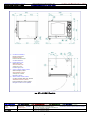
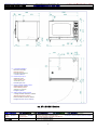
no. 07 x 1/1GN Electric
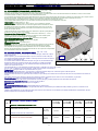
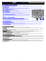
1.3A DIMENSIONI
1.3A DIMENSIONS
1.3A ABMESSUNGEN
1.3A DIMENSIONS
1.3A MEDIDAS
Modelli
Modèles
Dimensioni
Dimensions
Capacità e distanza (passo) tra le teglie
Capacité et écart entre les grilles
Models
Modelos
Dimensions
Medidas
Capacity and distance between trays
Capacidad y distancia (paso) entre las fuentes
Modelle Abmessungen Fassungsvermögen und Abstand der Bleche
07 x 1/1GN
14 x 1/2GN
Electric cm 80 x 81 x h82
n°07 x 1/1 GASTRO NORM
n°14 x 1/2 GASTRO NORM
67 mm
A
Connessione elettrica
Electrical connection
Elektroanschluss
Branchement électrique
Conexión eléctrica
B Entrata acqua φ 3/4″
Water inlet
φ
3/4”
Wasserzufuhr φ 3/4”
Arrivée eau
φ
3/4″
Entrada agua φ 3/4″
C Scarico camera cottura φ 40mm
Water drainage
φ
40mm
Wasserablauf φ 40mm
Vidange eau
φ
40mm
Desagüe φ 40mm
D Sfiato camera cottura φ 60mm
Cooking chamber relief valve
φ
60mm
Ablaßventil Garraum φ 60mm
Event chambre de cuisson
φ
60mm
Desagüe camara coccion
φ 60mm

ISTRUZIONI PER L’INSTALLATORE
INSTRUCTIONS FOR THE INSTALLER
ANLEITUNGEN FÜR DEN INSTALLATEUR
NOTICE POUR L'INSTALLATEUR
INSTRUCCIONES PARA EL INSTALADOR
COMPACT Combi Direct 7 / 11 x 1/1GN 7 / 11 x 2/1GN Var-03
5
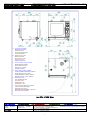
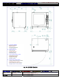
no. 07 x 1/1GN Gas
1.3B DIMENSIONI
1.3B DIMENSIONS
1.3B ABMESSUNGEN
1.3B DIMENSIONS
1.3B MEDIDAS
Modelli
Modèles
Dimensioni
Dimensions
Capacità e distanza (passo) tra le teglie
Capacité et écart entre les grilles
Models
Modelos
Dimensions
Medidas
Capacity and distance between trays
Capacidad y distancia (paso) entre las fuentes
Modelle Abmessungen Fassungsvermögen und Abstand der Bleche
07 x 1/1GN
14 x 1/2GN
Gas cm 80 x 84 x h82
n°07 x 1/1 GASTRO NORM
n°14 x 1/2 GASTRO NORM
67 mm
A
Connessione elettrica
Electrical connection
Elektroanschluss
Branchement électrique
Conexión eléctrica
B Entrata acqua φ 3/4″
Water inlet
φ
3/4”
Wasserzufuhr φ 3/4”
Arrivée eau
φ
3/4″
Entrada agua φ 3/4″
C Scarico camera cottura φ 40mm
Water drainage
φ
40mm
Wasserablauf φ 40mm
Vidange eau
φ
40mm
Desagüe φ 40mm.
D Sfiato camera cottura φ 60mm
Cooking chamber relief valve
φ
60mm
Ablaßventil Garraum φ 60mm
Event chambre de cuisson
φ
60mm
Desagüe camara coccion
φ 60mm
E Entrata gas φ 1/2″
1/2“ coupling gas inlet
Gaszufuhr φ 1/2“
Arrivée gaz
φ
1/2“
Entrada gas φ 1/2“
F Scarico fumi combustione φ 120mm
φ
120 mm fumes discharge
Abgasleitung φ 120mm.
Évacuation fumées brûlées
φ
120 mm
Descarga humo
φ 120mm

ISTRUZIONI PER L’INSTALLATORE
INSTRUCTIONS FOR THE INSTALLER
ANLEITUNGEN FÜR DEN INSTALLATEUR
NOTICE POUR L'INSTALLATEUR
INSTRUCCIONES PARA EL INSTALADOR
COMPACT Combi Direct 7 / 11 x 1/1GN 7 / 11 x 2/1GN Var-03
6
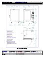
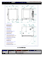
no. 11 x 1/1GN Electric
1.3C DIMENSIONI
1.3C DIMENSIONS
1.3C ABMESSUNGEN
1.3C DIMENSIONS
1.3C MEDIDAS
Modelli
Modèle
Dimensioni
Dimensions
Capacità e distanza (passo) tra le teglie
Capacité et écart entre les grilles
Models
Modelos
Dimensions
Medidas
Capacity and distance between trays
Capacidad y distancia (paso) entre las fuentes
Modelle Abmessungen Fassungsvermögen und Abstand der Bleche
11 x 1/1 GN
22 x 1/2 GN
Electric cm 80 x 81 x h110
n°11 x 1/1 GASTRO NORM
n°22 x 1/2 GASTRO NORM
67 mm
A
Connessione elettrica
Electrical connection
Elektroanschluss
Branchement électrique
Conexión eléctrica
B Entrata acqua φ 3/4″
Water inlet
φ
3/4”
Wasserzufuhr φ 3/4”
Arrivée eau
φ
3/4″
Entrada agua φ 3/4″
C Scarico camera cottura φ 40mm
Water drainage
φ
40mm
Wasserablauf φ 40mm
Vidange eau
φ
40mm
Desagüe φ 40mm
D Sfiato camera cottura φ 60mm
Cooking chamber relief valve
φ
60mm
Ablaßventil Garraum φ 60mm
Event chambre de cuisson
φ
60mm
Desagüe camara coccion
φ 60mm

ISTRUZIONI PER L’INSTALLATORE
INSTRUCTIONS FOR THE INSTALLER
ANLEITUNGEN FÜR DEN INSTALLATEUR
NOTICE POUR L'INSTALLATEUR
INSTRUCCIONES PARA EL INSTALADOR
COMPACT Combi Direct 7 / 11 x 1/1GN 7 / 11 x 2/1GN Var-03
7
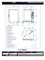
no. 11 x 1/1GN Gas
1.3D DIMENSIONI
1.3D DIMENSIONS
1.3D ABMESSUNGEN
1.3D DIMENSIONS
1.3D MEDIDAS
Modelli
Modèle
Dimensioni
Dimensions
Capacità e distanza (passo) tra le teglie
Capacité et écart entre les grilles
Models
Modelos
Dimensions
Medidas
Capacity and distance between trays
Capacidad y distancia (paso) entre las fuentes
Modelle Abmessungen Fassungsvermögen und Abstand der Bleche
11 x 1/1 GN
22 x 1/2 GN
Gas cm 80 x 84 x h110 n°11 x 1/1 GASTRO NORM 67 mm
A
Connessione elettrica
Electrical connection
Elektroanschluss
Branchement électrique
Conexión eléctrica
B Entrata acqua φ 3/4″
Water inlet
φ
3/4”
Wasserzufuhr φ 3/4”
Arrivée eau
φ
3/4″
Entrada agua φ 3/4″
C Scarico camera cottura φ 40mm
Water drainage
φ
40mm
Wasserablauf φ 40mm
Vidange eau
φ
40mm
Desagüe φ 40mm.
D Sfiato camera cottura φ 60mm
Cooking chamber relief valve
φ
60mm
Ablaßventil Garraum φ 60mm
Event chambre de cuisson
φ
60mm
Desagüe camara coccion
φ 60mm
E Entrata gas φ 1/2″
1/2“ coupling gas inlet
Gaszufuhr φ 1/2“
Arrivée gaz
φ
1/2“
Entrada gas φ 1/2“
F Scarico fumi combustione φ 120mm
φ
120 mm fumes discharge
Abgasleitung φ 120mm.
Évacuation fumées brûlées
φ
120 mm
Descarga humo
φ 120mm

ISTRUZIONI PER L’INSTALLATORE
INSTRUCTIONS FOR THE INSTALLER
ANLEITUNGEN FÜR DEN INSTALLATEUR
NOTICE POUR L'INSTALLATEUR
INSTRUCCIONES PARA EL INSTALADOR
COMPACT Combi Direct 7 / 11 x 1/1GN 7 / 11 x 2/1GN Var-03
8
no. 07 x 2/1GN Electric
1.3E DIMENSIONI
1.3E DIMENSIONS
1.3E ABMESSUNGEN
1.3E DIMENSIONS
1.3E MEDIDAS
Modelli
Modèles
Dimensioni
Dimensions
Capacità e distanza (passo) tra le teglie
Capacité et écart entre les grilles
Models
Modelos
Dimensions
Medidas
Capacity and distance between trays
Capacidad y distancia (paso) entre las fuentes
Modelle Abmessungen Fassungsvermögen und Abstand der Bleche
07 x 2/1GN
14 x 1/1GN
Electric cm 105 x 93 x h 82
n°07 x 2/1 GASTRO NORM
n°14 x 1/1 GASTRO NORM
67 mm
A
Connessione elettrica
Electrical connection
Elektroanschluss
Branchement électrique
Conexión eléctrica
B Entrata acqua φ 3/4″
Water inlet
φ
3/4”
Wasserzufuhr φ 3/4”
Arrivée eau
φ
3/4″
Entrada agua φ 3/4″
C Scarico camera cottura φ 50mm
Water drainage
φ
50mm
Wasserablauf φ 50mm
Vidange eau
φ
50mm
Desagüe φ 50mm.
D Sfiato camera cottura φ 60mm
Cooking chamber relief valve
φ
60mm
Ablaßventil Garraum φ 60mm
Event chambre de cuisson
φ
60mm
Desagüe camara coccion
φ 60mm

ISTRUZIONI PER L’INSTALLATORE
INSTRUCTIONS FOR THE INSTALLER
ANLEITUNGEN FÜR DEN INSTALLATEUR
NOTICE POUR L'INSTALLATEUR
INSTRUCCIONES PARA EL INSTALADOR
COMPACT Combi Direct 7 / 11 x 1/1GN 7 / 11 x 2/1GN Var-03
9
no. 11 x 2/1GN Electric
1.3G DIMENSIONI
1.3G DIMENSIONS
1.3G ABMESSUNGEN
1.3G DIMENSIONS
1.3G MEDIDAS
Modelli
Modèles
Dimensioni
Dimensions
Capacità e distanza (passo) tra le teglie
Capacité et écart entre les grilles
Models
Modelos
Dimensions
Medidas
Capacity and distance between trays
Capacidad y distancia (paso) entre las fuentes
Modelle Abmessungen Fassungsvermögen und Abstand der Bleche
11 x 2/1GN
22 x 1/1GN
Electric cm 105 x 93 x h110
n°11 x 2/1 GASTRO NORM
n°22 x 1/1 GASTRO NORM
67mm
A
Connessione elettrica
Electrical connection
Elektroanschluss
Branchement électrique
Conexión eléctrica
B Entrata acqua φ 3/4″
Water inlet
φ
3/4”
Wasserzufuhr φ 3/4”
Arrivée eau
φ
3/4″
Entrada agua φ 3/4″
C Scarico camera cottura φ 50mm
Water drainage
φ
50mm
Wasserablauf φ 50mm
Vidange eau
φ
50mm
Desagüe φ 50mm.
D Sfiato camera cottura φ 60mm
Cooking chamber relief valve
φ
60mm
Ablaßventil Garraum φ 60mm
Event chambre de cuisson
φ
60mm
Desagüe camara coccion
φ 60mm

ISTRUZIONI PER L’INSTALLATORE
INSTRUCTIONS FOR THE INSTALLER
ANLEITUNGEN FÜR DEN INSTALLATEUR
NOTICE POUR L'INSTALLATEUR
INSTRUCCIONES PARA EL INSTALADOR
COMPACT Combi Direct 7 / 11 x 1/1GN 7 / 11 x 2/1GN Var-03
10
no. 11 x 2/1GN Gas
1.3H DIMENSIONI
1.3H DIMENSIONS
1.3H ABMESSUNGEN
1.3H DIMENSIONS
1.3H MEDIDAS
Modelli
Modèles
Dimensioni
Dimensions
Capacità e distanza (passo) tra le teglie
Capacité et écart entre les grilles
Models
Modelos
Dimensions
Medidas
Capacity and distance between trays
Capacidad y distancia (paso) entre las fuentes
Modelle Abmessungen Fassungsvermögen und Abstand der Bleche
11 x 2/1GN
22 x 1/1GN
Gas cm 105 x 96 x h110
n°11 x 2/1 GASTRO NORM
n°22 x 1/1 GASTRO NORM
67mm
A
Connessione elettrica
Electrical connection
Elektroanschluss
Branchement électrique
Conexión eléctrica
B Entrata acqua φ 3/4″
Water inlet
φ
3/4”
Wasserzufuhr φ 3/4”
Arrivée eau
φ
3/4″
Entrada agua φ 3/4″
C Scarico camera cottura φ 50mm
Water drainage
φ
50mm
Wasserablauf φ 50mm
Vidange eau
φ
50mm
Desagüe φ 50mm.
D Sfiato camera cottura φ 60mm
Cooking chamber relief valve
φ
60mm
Ablaßventil Garraum φ 60mm
Event chambre de cuisson
φ
60mm
Desagüe camara coccion
φ 60mm
E Entrata gas φ 1/2″
1/2“ coupling gas inlet
Gaszufuhr φ 1/2“
Arrivée gaz
φ
1/2“
Entrada gas φ 1/2“
F Scarico fumi combustione φ 120mm
φ
120 mm fumes discharge
Abgasleitung φ 120mm.
Évacuation fumées brûlées
φ
120mm
Descarga humo
φ 120mm

ISTRUZIONI PER L’INSTALLATORE
INSTRUCTIONS FOR THE INSTALLER
ANLEITUNGEN FÜR DEN INSTALLATEUR
NOTICE POUR L'INSTALLATEUR
INSTRUCCIONES PARA EL INSTALADOR
COMPACT Combi Direct 7 / 11 x 1/1GN 7 / 11 x 2/1GN Var-03
11
n° 07 x 1/1GN
n° 11 x 1/1GN

ISTRUZIONI PER L’INSTALLATORE
INSTRUCTIONS FOR THE INSTALLER
ANLEITUNGEN FÜR DEN INSTALLATEUR
NOTICE POUR L'INSTALLATEUR
INSTRUCCIONES PARA EL INSTALADOR
COMPACT Combi Direct 7 / 11 x 1/1GN 7 / 11 x 2/1GN Var-03
12
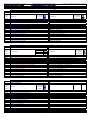
1.6 TABELLA DATI TECNICI Allacciamento elettrico
1.6 ECHNICAL DATA TABLE Electric connection
1.6 TABELLE TECHNISCHE DATEN Elektroanschluß
1.6 TABLEAU DES DONNEES TECHNIQUES Branchement électrique
1.6 TABLA DATOS TÉCNICOS Conexión eléctrica hornos
Modelli Potenza assorbita e voltaggio n° e potenza motori
Potenza riscaldante
Corrente assorbita Sez. cavo alimentazione
Model
s
Power loading and voltage no. and motor powe
r
Heating powe
r
A
bsorbed current Feed cable section
Modelle Leistung und Spannung
A
nz.und Motorleistung
Heizleistung
Strom Querschnitt Anschlusskabel
Modèle Puissance absorbée et voltage n° et puissance moteu
r
Puissance de chauffe
Courant absorbé Section cable
alimentation
Modelos Consumo de potencia y voltaje n° y potencia motores
Potencia calefacción
Consumo corriente Sección cable alimentacion
Stanrdard
07 x 1/1GN gas
0.3 kW 230V ∼ 50/60Hz
1 x 0.25 kW / 1.6A n°3 x 1.5 mm
2
11 x 1/1GN gas
0.4 kW 230V ∼ 50/60Hz
1 x 0.37 kW / 2.5A n°3 x 1.5 mm
2
07 x 2/1GN gas
11 x 2/1GN gas
0.6 kW 400V+3N ∼ 50/60Hz
1 x 0.55 kW / 1A n°5 x 1.5 mm
2
07 x 1/1GN electric
8.2 kW 400V+3N ∼ 50/60Hz
1 x 0.25 kW 8.0 kW 13A n°5 x 2.5 mm
2
11 x 1/1GN electric
16.4 kW 400V+3N ∼ 50/60Hz
1 x 0.37 kW 16 kW 25A n°5 x 6 mm
2
07 x 2/1GN electric
16.4 kW 400V+3N ∼ 50/60Hz
1 x 0.37 kW 16 kW 25A n°5 x 6 mm
2
11 x 2/1GN electric
23 kW 400V+3N ∼ 50/60Hz
1 x 0.55 kW 22.5 kW 34A n°5 x 10 mm
2
No standard
La pagina si sta caricando...
La pagina si sta caricando...

ISTRUZIONI PER L’INSTALLATORE
INSTRUCTIONS FOR THE INSTALLER
ANLEITUNGEN FÜR DEN INSTALLATEUR
NOTICE POUR L'INSTALLATEUR
INSTRUCCIONES PARA EL INSTALADOR
COMPACT Combi Direct 7 / 11 x 1/1GN 7 / 11 x 2/1GN Var-03
15
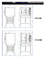
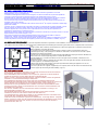
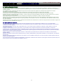
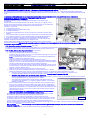
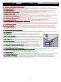
2.0 INSTALLAZIONE DELL’APPARECCHIO
Leggere attentamente questo libretto che fornisce importanti indicazioni riguardanti la sicurezza
dell’installazione, l’uso e la manutenzione.
L’installazione dell’apparecchio deve essere eseguita, solo ed esclusivamente, da personale qualificato
seguendo le istruzioni riportate nel presente manuale e nel rispetto delle norme in vigore.
Gli impianti del gas, dell’acqua, dell’energia elettrica ed i locali nei quali gli apparecchi vengono installati
devono essere eseguiti in conformità alle corrispondenti norme di installazione e sicurezza.
I forni funzionanti a gas, devono sempre essere posizionati sotto una cappa di buon funzionamento che
asporterà vapori e gas combusti.
(Il fabbisogno di aria per la combustione deve essere almeno di 2m
3
per ogni kW di potenza assorbita dagli
apparecchi installati).
Collocare il forno in ambiente aerato e procedere alla messa a livello agendo sui piedini regolabili, in modo
tale che rimanga una distanza minima di 6cm tra il fondo del forno ed il piano di appoggio dei piedini.
Installare l’apparecchio in una posizione che ne permetta l’accesso al lato dx per le operazioni di
installazione, manutenzione e assistenza tecnica.
Mantenere le distanze minime tra le pareti del forno, (posteriore e laterale dx) e le pareti in muratura o le altre
apparecchiature come indicato in figura n°2.0A.
Rimuovere manualmente le pellicole protettive dalle parti in acciaio, prima di mettere in funzione
l’apparecchio, evitando l’uso di sostanze abrasive e/o di oggetti metallici.
Qualora il forno venga collocato sugli appositi supporti, da noi forniti su richiesta, fare attenzione che il foro
centrale dei piedini si innesti nel perno del supporto, questo incastro ne garantisce la stabilità, (Fig. 2.0).
2.0 INSTALLING THE APPLIANCE
Read this handbook through carefully as it provides important information to guarantee a safe installation, use and maintenance.
The appliance must be installed only and exclusively by qualified personnel following the instructions given herein and in compliance with current laws in
force.
The gas system, water, electricity and the premises on which the appliances are installed comply with the
relative installation and safety standards.
Gas powered ovens must always be installed under an efficient suction hood that takes steam and
combusted gases away. (The quantity of air needed for combustion is at least 2m
3
for each kW of power
absorbed by the appliances installed).
Install the oven on aerated premises and level with the adjustable feet, keeping at least 6cm between the
bottom of the oven and the supporting surface on which the feet stand.
Install the appliance in a position that allows access to the right side for installation, maintenance and
technical assistance.
Maintain the minimum distances between the oven walls, (rear and right side) and either the brick walls or
the other appliances, as illustrated in figure 2.0A.
Take the protective film off the stainless steel parts by hand before starting the appliance. Do not use
abrasive substances and/or metal objects.
If the oven is placed on its supports, supplied by us on request, make sure the centre hole of the feet snap
on to the support pin which will guarantee stability, (Fig. 2.0).
2.0 GERÄTEINSTALLATION
Dieses Handbuch aufmerksam durchlesen, da es wichtige Informationen über die Sicherheit bei
der Aufstellung, die Bedienung und Wartung enthält.
Die Geräteinstallation darf ausschließlich von Fachpersonal, gemäß den in diesem Handbuch
angeführten Anleitungen und den gültigen Normen durchgeführt werden.
Die Gas-, Wasser- und Stromversorgungsanlagen, sowie der Aufstellort, müssen den geltenden
Installations- und Sicherheitsbestimmungen entsprechen.
Die gasbetriebenen Backöfen müssen immer unter einer einwandfrei funktionierenden
Dunstabzugshaube aufgestellt werden, die Dämpfe und Abgase ableitet. (Die für die Verbrennung
nötige Luftzufuhr muss mindestens 2m
3
pro kW aufgenommener Leistung entsprechen.
Den Backofen in einem gut belüfteten Raum aufstellen und mit den höhenverstellbaren Füßen
waagrecht ausrichten, sodass ein Mindestabstand von 6cm zwischen dem Backofenboden und
der Stellfläche der Füße bleibt.
Das Gerät so aufstellen, dass die rechte Seite des Geräts für Installations-, Wartungs- und
Reparaturarbeiten zugänglich sind.
Den Mindestabstand zwischen den Wänden des Backofens (hintere Wand und rechte
Seitenwand) und Mauern oder anderen Geräten beachten (Abb.2.0A).
Vor Inbetriebnahme des Geräts die Schutzfolie von den Stahlteilen abziehen. Dafür dürfen keine
Scheuermittel bzw. Metallgegenstände verwendet werden.
Sollte der Backofen auf den dafür vorgesehenen Abstellflächen - auf Anfrage lieferbar - aufgestellt
werden, ist darauf zu achten, dass der entsprechende Stellzapfen der Abstellfläche in das zentrale
Loch im Stellfuß eingeschoben wird, wodurch ein fester und sicherer Stand des Backofens
gewährleistet wird, (Abb. 2.0).
50 cm
15 cm
1
0
c
m
Fig. 2.0
Abb. 2.0
Fig.2.0A
Abb.2.0A
La pagina si sta caricando...

ISTRUZIONI PER L’INSTALLATORE
INSTRUCTIONS FOR THE INSTALLER
ANLEITUNGEN FÜR DEN INSTALLATEUR
NOTICE POUR L'INSTALLATEUR
INSTRUCCIONES PARA EL INSTALADOR
COMPACT Combi Direct 7 / 11 x 1/1GN 7 / 11 x 2/1GN Var-03
17
8
+
3
0
c
m
1
0
c
m
m
i
n
.
1
8
0
c
m
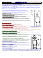
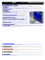
Fig. 2.1A
A
bb. 2.1A
3 x d d
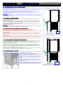
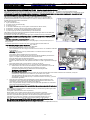
2.1 COLLEGAMENTO AL CAMINO APPARECCHI FUNZIONANTI A GAS
Gli apparecchi sono provvisti di un camino per l’evacuazione dei prodotti della combustione che deve essere collegato secondo una delle modalità
illustrate nelle Fig. 2.1 – 2.1A previste dalle normative di installazione.
2.1A Evacuazione fumi naturale tipo B23: (Fig. 2.1)
Il collegamento è eseguito ad un camino a tiraggio naturale, di sicura efficienza, non compreso nella dotazione standard del forno, con scarico dei
fumi di combustione direttamente all’esterno.
2.1B Evacuazione fumi forzata tipo A3: (Fig. 2.1A)
L’alimentazione del gas all’apparecchio deve essere asservita direttamente al sistema di evacuazione forzata e deve interrompersi qualora la portata
di questo scenda sotto i valori prescritti dalle normative di installazione in vigore.
Il ripristino dell’alimentazione del gas all’apparecchio deve potersi eseguire solo manualmente.
Nel caso di installazione sotto cappa, la parte terminale del condotto dei fumi di scarico dell’apparecchio
deve trovarsi alla misura minima di 1.8m dalla superficie di appoggio dello stesso, la sezione di uscita del
condotto dei fumi di scarico deve essere disposta entro il perimetro di base della cappa.
2.1 CONNECTING TO THE FLUE
GAS POWERED OVENS
The appliances are provided with a flue for eliminating the products of combustion.
This flue must be connected as illustrated in Figures 2.1 – 2.1A as established by the installation rules.
2.1A Natural fumes evacuation type B23:
(Fig. 2.1)
Connection is made to an effective natural draught flue by means of a wind proof fitting, not part of the
oven’s standard fittings, with discharge of the combustion fumes directly into the atmosphere.
2.1B Forced fumes evacuation type a3:
(Fig. 2.1A)
The supply of gas to the appliance must be interlocked directly to the forced evacuation system and must
shutdown whenever the latter’s rate of flow drops below the values prescribed by the current installation
standards.
It should only be possible to restore the supply of gas by hand.
If the appliance is installed under an extractor, the end part of the appliance’s exhaust gas pipe should be at
least 1.8m from the surface on which it stands.
The exhaust pipe’s outlet section should be positioned inside the base perimeter of the extractor.
2.1 ANSCHLUSS AN DEN KAMIN GASBEHEIZTE ÖFEN
Die Geräte sind mit einem Kamin für die Abgasleitung ausgestattet, der entsprechend den Installationsnormen
nach einer der beiden Abbildungen 2.1 – 2.1A angeschlossen werden muss.
2.1A Natürliche Abgasleitung Typ B23: (Abb. 2.1)
Der Anschluss muss mit einem Windschutzanschluss (nicht im Standard-Lieferumfang des Backofens) an
einen sicheren Kamin mit natürlichem Abzug und direkt nach außen vorgenommen werden.
2.1B Forcierte Abgasleitung Typ A3: (Abb. 2.1A)
Die Gasversorgung des Geräts muss direkt von der forcierten Abgasleitung abgesichert werden, wobei sich die Versorgung unterbrechen muss, wenn
die Leistung der Abgasleitung unter die von der gültigen Installationsnorm vorgegebenen Werte sinkt.
Die Wiederherstellung der Gaszufuhr darf nur manuell möglich sein.
Bei Installation unter einer Dunstabzugshaube muss das Ende der Abgasleitung des Geräts mindestens 1.8m von der Stellfläche des Geräts entfernt
sein und der Querschnitt am Ausgang der Abgasleitung muss sich innerhalb des Umfangs der Dunstabzugshaube befinden.
2.1 RACCORDEMENT AU CONDUIT DE CHEMINÉE
FOURS A GAZ
Les appareils sont équipés d'un conduit de cheminée pour l'évacuation des produits de combustion, qui doit être raccordé selon une des modalités
illustrées aux figures 2.1 – 2.1A, prévues par les normes d'installation.
2.1A Évacuation naturelle des fumées modèle B23:
(Fig. 2.1)
Le raccordement est effectué à un conduit de cheminée à tirage naturel, d'efficacité sûre à l'aide d'un
raccord anti-débordement, non compris dans l'équipement standard du four, avec évacuation des fumées
de combustion directement à l'extérieur.
2.1B Évacuation forcée des fumées modèle A3:
(Fig. 2.1A)
L’arrivée du gaz à l'appareil doit être raccordée directement au système d'évacuation forcée et doit
s'interrompre si le débit de ce dernier descend sous les valeurs prescrites par les normes d'installation en
vigueur.
La remise en fonction de l'arrivée du gaz ne peut être effectuée que manuellement.
Dans le cas d'une installation sous une hotte, la partie terminale du conduit d'évacuation des fumées de
l'appareil, doit être placée à la mesure minimale de 1.8m de la superficie d'appui de celui-ci. La section de
débouché du conduit d'évacuation des fumées doit être placée dans le périmètre de base de la hotte.
2.1 CONEXIÓN CON LA CHIMENEA HORNOS DE GAS
Los aparatos vienen equipados con chimenea para evacuar los productos de la combustión, que es preciso
enlazar según una de las modalidades ilustradas en las fig. 2.1 – 2.1A previstas por las normas de
instalación.
2.1A Evacuación natural de los humos: (Fig. 2.1)
La conexiòn se realiza con una chimenea de tiro natural, de eficiencia comprobada mediante la conexión
antiviento, no incluido en el equipamiento standard del horno, con expulsión de los humos de combustión
directamente al exterior.
2.1B Evacuación forzada de los humos: (Fig. 2.1A)
La alimentación del gas para el aparato debe estar sometido directamente al sistema de evacuación
forzada y debe cortarse cuando el caudal de dicho sistema descienda por debajo de los valores prescritos
por las normas de instalación vigentes.
El restablecimiento de la alimentación del gas para el aparato debe poder efectuarse sólo manualmente.
En caso de instalación bajo campana, la parte terminal del conducto de los humos de escape del aparato debe quedar a una medida mínima de 1.8m
de la superficie de apoyo del aparato, la sección de salida del conducto de los humos de escape debe quedar dentro del perímetro de base de la
campana.
Fig. 2.1
A
bb. 2.1

ISTRUZIONI PER L’INSTALLATORE
INSTRUCTIONS FOR THE INSTALLER
ANLEITUNGEN FÜR DEN INSTALLATEUR
NOTICE POUR L'INSTALLATEUR
INSTRUCCIONES PARA EL INSTALADOR
COMPACT Combi Direct 7 / 11 x 1/1GN 7 / 11 x 2/1GN Var-03
18
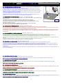
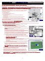
2.2 COLLEGAMENTO ELETTRICO
L’apparecchio consegnato è predisposto per il funzionamento alla tensione riportata sulla targhetta “caratteristiche” applicata sul fianco dx
dell’apparecchio.
La morsettiera di allacciamento è accessibile dal lato dx dell’apparecchio, smontando il fianco di rivestimento.
Prima di procedere all’applicazione del cavo, smontare la protezione in acciaio fissata al basamento del forno con le relative viti, (vedi fig.2.2A)
introdurre il cavo nel raccordo di bloccaggio e introdurlo nel vano della morsettiera dal foro con guarnizione del basamento in prossimità della stessa.
A collegamento elettrico eseguito rimontare la protezione in acciaio precedentemente rimossa.
Il cavo flessibile, per il collegamento elettrico, deve avere caratteristiche non inferiori a quello con isolamento in gomma H07 RN-F con la sezione dei
conduttori riportata nei dati tecnici.
Installare, a monte dell’apparecchio, un interruttore automatico di protezione e di portata adeguata, che abbia un’apertura dei contatti superiore a 3 mm.
E’ indispensabile collegare l’apparecchiatura ad un efficiente impianto di terra; a tale scopo sulla morsettiera di allacciamento c’è il morsetto, con il
relativo simbolo , al quale deve essere connesso il conduttore di terra.
L’apparecchiatura deve trovare inserimento in un sistema equipotenziale, (Fig. 2.2) la cui efficacia deve
essere in conformità alla normativa in vigore. Il collegamento deve essere eseguito tramite la vite collocata in
prossimità del pressacavo di alimentazione, contrassegnata dalla sigla EQUIPOTENTIAL.
Il Costruttore declina ogni responsabilità qualora questa importante norma antinfortunistica non
venga rispettata.
2.2A VERIFICA SENSO ROTAZIONE MOTORI (solo per motori trifasi)
Verificare che il senso di rotazione dei ventilatori corrisponda alla direzione della freccia riportata nel
pannello in acciaio inossidabile di convogliamento aria, posto all’interno della camera di cottura, qualora la
rotazione risulti contraria, invertire tra loro due fasi sulla morsettiera di alimentazione.
2.2 ELECTRICAL CONNECTION
When the appliance is delivered it is set to work at the voltage given on the rating plate affixed on the right
side of the appliance.
The terminal board used for connecting can be accessed from the right of the appliance, removing the side
panel.
Before connecting the cable, remove the steel protection fixed to the ovens base with its specific screws, (see
Fig. 2.2A)insert the cable in the clamp-connector and then in the terminal board zone, passing through the
hole with the gasket near the terminal board. Once the electric connection has been carried out, reassemble
the steel protection previously removed.
The specifications of the flexible cable for the electrical connection should be no lower than those of the type with rubber insulation H07 RN-F, with the
cross section of the wires as given in the technical data.
Install a circuit breaker of a suitable capacity upstream from the appliance, making sure it
has an opening between the contacts of at least 3-mm.
It is essential to connect the appliance to an effective earthing system; (Fig. 2.2) for this
purpose the relative terminal with the symbol to which the earth wire is to be
connected is on the terminal board.
The effectiveness of the equipotential system of which the appliance is part of, must
conform to current standards. Connect using the screw you find near the power cable’s
relief cable strain, marked with the word EQUIPOTENTIAL.
The Manufacturer declines all and every responsibility if this important accident
prevention norm is not complied with.
2.2A CHECKING MOTOR ROTATION DIRECTION (only for three-phase motors)
Check that the fans’ rotation direction is the same as that of the arrow on the stainless steel
air-conveying panel, located inside the oven. If they are rotating in the opposite direction,
reverse two phases on the supply terminal board.
2.2 ELEKTROANSCHLUSS
Das Gerät wird werksgemäß für den Betrieb mit der auf dem Typenschild (auf der rechten
Seite des Geräts angebracht) angegebenen Versorgungsspannung eingestellt.
Die Anschlussklemmleiste wird durch Abnehmen der rechten Seitenwand zugänglich.
Bevor dem Netzkabel zu verbinden, das Schutz-Stahlblech, das zur Grundfläche des Ofens
mit den spezifischen Schrauben befestigt ist, abnehmen (Abb. 2.2A). Das Kabel in den
Kabelklemmen stecken und durch das Loch (im Raum der Klemmleiste) mit der Dichtung in
der Nähe vom Klemmleiste einführen.
Als die elektrische Verbindung durchgeführt wurde, nochmals das Schutz-Stahlblech wieder anschrauben.
Der Anschluss muss mit einem Netzkabel mit den Eigenschaften des Typs H07 RN-F mit Gummiisolierung durchgeführt werden. Die Leiterquerschnitte
müssen jenen unter „Technische Daten” angeführten entsprechen.
Vor dem Gerät muss ein automatischer Schutzschalter, mit mindestens 3 mm Kontaktöffnungsweite, eingebaut werden.
Das Gerät muss unbedingt geerdet werden. Zu diesem Zweck befindet sich auf der Anschlussklemmleiste eine Klemme mit entsprechendem Symbol
, an die der Erdleiter angeschlossen werden muss.
Des weiteren muss das Gerät in ein Potentialausgleichssystem (Abb. 2.2) eingeschlossen werden, dessen Wirksamkeit den geltenden Richtlinien
entsprechen muss. Der Anschluss wird mit der Schraube durchgeführt, die mit EQUIPOTENTIAL gekennzeichnet ist und sich in der Nähe der
Kabelklemme befindet.
Die Herstellerfirma übernimmt bei Nichtbeachtung dieser Unfallverhütungsmaßnahme keine Verantwortung.
2.2A ÜBERPRÜFUNG ROTATIONSRICHTUNG DER MOTOREN (nur für Dreiphasenmotoren)
Sicherstellen, dass die Rotationsrichtung der Ventilatoren der Pfeilrichtung (an der Edelstahlplatte der Luftsammelleitung innerhalb des Garraums)
entspricht. Andernfalls, die beiden Phasen an der Versorgungsklemmleiste umkehren.
Fig. 2.2
Abb. 2.2
Fig. 2.2A
Abb. .2.2A
La pagina si sta caricando...

ISTRUZIONI PER L’INSTALLATORE
INSTRUCTIONS FOR THE INSTALLER
ANLEITUNGEN FÜR DEN INSTALLATEUR
NOTICE POUR L'INSTALLATEUR
INSTRUCCIONES PARA EL INSTALADOR
COMPACT Combi Direct 7 / 11 x 1/1GN 7 / 11 x 2/1GN Var-03
20
2.3 COLLEGAMENTO IDRAULICO - ENTRATA ACQUA (Fig. 2.3a – 2.3b)
I forni sono provvisti di un raccordo di entrata-acqua situato nel retro dell’apparecchiatura.
Porre sempre tra l’apparecchio e la rete di alimentazione dell’acqua una valvola di intercettazione con comando facilmente azionabile, si consiglia
inoltre il montaggio di un filtro a cartuccia sulla tubazione di entrata dell’acqua.
L’allacciamento idrico deve essere effettuato sempre con acqua fredda, l’elettrovalvola (B) alimenta il sistema di condensazione del vapore che
fuoriesce da tubo di scarico, l’elettrovalvole (A) e (A1) alimentano quello di generazione del vapore nella camera di cottura mentre l’elettrovalvole (C) e
(D) alimentano i sistemi di lavaggio e risciacquo della camera di cottura.
L’acqua di alimentazione deve essere idonea al consumo umano e avere le seguenti caratteristiche:
Temperatura: compresa tra 15 – 20°C
Durezza totale: compresa tra 4 e 8°Francesi, si consiglia di installare sempre un decalcificatore a monte dell’apparecchio, atto a mantenere il valore
della durezza dell’acqua entro detti valori, Il funzionamento del forno con acqua di durezza superiore porta alla formazioni di incrostazioni calcaree sulle
pareti della camera di cottura, eventuali interventi di assistenza tecnica necessari alla riparazione di danni causati dal calcare, non saranno considerati
“in garanzia”.
Pressione: compresa tra 100 e 200 KPa (1 – 2 bar).
N.B. valori di pressione più elevati comportano solo un dispendio del consumo di acqua e possono compromettere il corretto funzionamento di alcuni
componenti.
Concentrazione massima di ione cloruro (Cl-): inferiore a 150 mgr/litro.
Concentrazione di Cloro (Cl
2
): inferiore a 0.2 mg/litro.
Ph: maggiore di 7.
Conducibilità elettrica: compresa tra 50 e 2000 μS/cm.
Attenzione: L’utilizzo di sistemi di trattamento dell’acqua che determinano
valori diversi da quelli sopra indicati non è ammesso pena il totale decadimento
della garanzia. Eventuali impianti dosatori di sostanze atte a evitare la
formazione di incrostazioni nelle tubazioni (per esempio: dosatori di polifosfati)
sono altresì vietati perché possono compromettere il corretto funzionamento
dell’apparecchiatura.
2.3 HYDRAULIC CONNECTION – WATER INLET
(Fig. 2.3a – 2.3b)
The ovens have a water inlet coupling at the back.
Always install an on-off valve between the appliance and the water mains,
making sure it is easy to operate.
We also suggest installing a cartridge filter on the water inlet pipe.
Always connect to the cold water, the solenoid valve (B) which supplies the
steam condensation system that comes out of the drainpipe, while solenoid
valves (A) and (A1) supplies the system that generates steam for cooking
chamber, the solenoid valves (C) and (D) supply the washing and rinsing
systems of the cooking chamber.
The water must be suitable to human use with the following characteristics:
Temperature:
included between 15 – 20 °C
Total hardness:
included between 4 and 8 °French degree, it is advisable to
install a softener upstream from the appliance that will maintain the hardness
level at the mentioned values. The oven’s running with water that has a higher
hardness level will not be long before scale forms on the walls of the oven
and in this case the technical assistance required to repair such damage is not covered by the guarantee.
Pressure:
included between 100 and 200 KPa (1 – 2 bar).
Attention higher water pressure values result in increased water consumption and can compromise the correct functioning of some components.
Maximum chloride concentration (Cl-):
less than 150 mgr/litre.
Chlorine concentration (Cl
2
):
less than 0.2 mg/litre.
Ph:
more than 7.
Water conductivity:
included between 50 and 2000
μ
S/cm.
Attention:
Water treatment systems that bring to different values to the ones above mentioned automatically invalidate the guarantee.
The use of dosing systems designed to prevent the build-up of lime-scale in pipes (i.e. polyphosphate dosing systems) is also prohibited since it may
impair the performance of the appliance.
2.3 ANSCHLUSS ANS WASSERNETZ – WASSERZUFUHR (Abb. 2.3a – 2.3b)
Die Geräte sind auf der Rückseite mit einem Wasseranschluss ausgerüstet.
Zwischen dem Gerät und dem Wasserversorgungsnetz muss ein leicht zugängliches Absperrventil zwischengeschaltet werden.
Außerdem ist es ratsam, in der Wasserzuleitung einen Filter mit Einsatz zu montieren.
Der Wasseranschluss muss immer mit Kaltwasser erfolgen.
Das Elektroventil (B) versorgt das System der Dampfkondensierung, wobei der Dampf aus dem Abflussrohr austritt, während das Elektroventil (A) und
(A1) das System zur Dampferzeugung im Garraum versorgt; die Elektroventile (C) und (D) versorgen die Reinigung und die Spülung im Garraum.
Die Wasserversorgung muss für den Menschengebrauch geeignet ist und das die folgenden Merkmale hat:
Temperatur: muß zwischen 15 und 20°C liegen
Wasserhärte: Diesem Gerät muß Wasser zugeführt werden, dass eine Härte von 4 bis 8 französischen Graden aufweist. Es wird empfohlen einen
Entkalker dem Gerät beizugeben, damit der Härtegrad des Wassers zwischen diesen Werten liegt. Wird Wasser mit höherem Härtegrad verwendet,
entstehen innerhalb kurzer Zeit Kalkablagerungen auf den Garraumwänden. Eventuelle, dadurch notwendige Reparaturen werden nicht von der
Garantie gedeckt.
Wasserdruck: zwischen 100 und 200 KPa (1 – 2 bar).
ACHTUNG. Höhere Drücke führen zu übermäßigen Wasserverbrauch und können wichtige Komponente beschädigen.
Maximale Chloridkonzentration (Cl-): unter 150 mgr/Liter.
Chlorkonzentration (Cl
2
): unter 0.2 mg/Liter.
Ph: über 7
Leitfähigkeit des Wassers: von 50 bis 2000 μS/cm.
Achtung: Die Verwendung anderer Wasseraufbereitungssysteme als das von der Herstellerfirma gelieferte ist unzulässig und führt zum vollständigen
Verfall der Garantie. Der Einsatz von Geräten zur Dosierung von Mitteln zur Vermeidung von Ablagerungen in den Rohrleitungen (z.B. Polyphosphat-
Dosierer) ist ebenfalls untersagt, da diese die einwandfreie Funktion der Maschine beeinträchigen können.
Fig. 2.3a
Abb. 2.3a
Electronic models
La pagina si sta caricando...

ISTRUZIONI PER L’INSTALLATORE
INSTRUCTIONS FOR THE INSTALLER
ANLEITUNGEN FÜR DEN INSTALLATEUR
NOTICE POUR L'INSTALLATEUR
INSTRUCCIONES PARA EL INSTALADOR
COMPACT Combi Direct 7 / 11 x 1/1GN 7 / 11 x 2/1GN Var-03
22
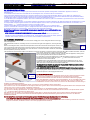
2.4 COLLEGAMENTO IDRAULICO - SCARICO ACQUA
I forni sono dotati di uno scarico acqua situato sul retro dell’apparecchio; il collegamento idraulico deve essere effettuato direttamente sull’estremità del
tubo di scarico in acciaio inox.
Lo scarico deve essere privo di sifone e realizzato con tubi rigidi e resistenti alla temperatura di 110°C.
E’ assolutamente necessario che il diametro del tubo di scarico non venga ridotto e che la sua
tubazione sia a pressione atmosferica, con l’opportuna presa d’aria a imbuto.
L’eventuale intasamento del tubo di scarico può provocare uscita di vapore dalla porta e cattivi odori
nella camera di cottura.
Attenzione: L’impianto di scarico deve essere installato in modo tale da evitare che eventuali vapori
emessi dalla presa d’aria a imbuto “air break” raggiungano le aperture di aereazione presenti sul fondo
del forno. (Fig. 2.4 e 2.4A)
2.4 PLUMBING – WATER DRAINAGE
Drainage for the water is at the back of the oven and must be connected directly to the end of the
stainless steel drainpipe.
The drain must have no trap and be made in rigid pipes that can withstand a temperature of 110°C.
Under no circumstances must pipe diameter be reduced. The actual pipe should be at atmospheric
pressure with the appropriate funnel type air intake.
If the drainpipe is clogged for any reason steam can escape from the door and bad smells can be
created inside in the oven.
Important:
The drain system must be installed so that any vapours coming from the open drain do not
enter the aeration vents under the appliance. (Fig. 2.4 and 2.4A).
2.4 ANSCHLUSS AN DAS WASSERNETZ – WASSERABLAUF
Die Backöfen sind auf der Rückseite mit einem Wasserablauf ausgerüstet; sodass der
Wasseranschluss direkt am Edelstahl-Ablaufrohr vorgenommen werden muss.
Der Ablauf darf keinen Siphon haben und muss aus bis zu 110°C hitzebeständig, unbiegsamen Rohren
hergestellt werden.
Der Durchmesser des Ablaufrohrs darf auf keinen Fall verringert werden und die Rohrleitung muss für
den atmosphärischen Druck geeignet und mit der notwendigen trichterförmigen Luftansaugung
ausgestattet sein.
Eine eventuelle Verstopfung des Ablaufrohrs kann einen Dampfaustritt aus der Tür und eine Geruchbildung im Garraum zur Folge haben.
Achtung: Die Abluftanlage muß so installiert werden, dass eventuell vom „Air-Break“ austretende
Dämpfe nicht in die Belüftungsöffnungen am Boden des Gerätes gelangen können. (Abb. 2.4 und 2.4A)
2.4 RACCORDEMENT HYDRAULIQUE – VIDANGE D'EAU
Les fours sont équipés d’un tuyau de vidange de l’eau placé à l’arrière de l'appareil; le raccordement
hydraulique doit être effectué directement sur l'extrémité du tuyau de vidange en acier inox.
Le système de vidange ne doit pas avoir de siphon et doit être réalisé avec des tuyaux rigides et
résistants à une température de 110°C.
Le diamètre du tuyau de vidange ne peut pas être réduit et il est absolument nécessaire que le
raccordement au conduit soit à pression atmosphérique, avec une adéquate prise d’air à entonnoir.
L’obstruction du tuyau de vidange peut provoquer une sortie de vapeur par la porte du four et des
mauvaises odeurs à l’intérieur de l’enceinte de cuisson.
Attention: installer le système d’évacuation de façon à éviter l’émission de vapeurs par l’Air-break dans
les conduits d’aération installés dans le fond de l’appareil. (Fig. 2.4 et 2.4A)
2.4 CONEXIÓN HÍDRICA – DESAGÜE
Los hornos disponen de un desagüe situado en la parte trasera del aparato; la conexión hídrica debe ser
efectuada directamente en el extremo del tubo de desagüe en acero inoxidable.
El desagüe no debe tener sifón y debe realizarse con tubos
rígidos y resistentes a temperaturas de 110°C.
Es terminantemente necesario que el diámetro del tubo de
desagüe no se reduzca y que su tubería quede a la presión
atmosférica, con la oportuna toma de aire con forma de
embudo.
El eventual atasco del tubo de desagüe puede causar la
salida de vapor por la puerta del horno y malos olores en la
cámara de cocción.
Atención: instalar el sistema de evacuación de modo che los
vapores emitidos por el Air-Break alcancen la abertura de
aireación colocada al fondo del aparato. (Fig. 2.4 y 2.4A)
2
°m
i
n
.
> 1 cm
< 30 cm
2
°
m
i
n
.
1>cm
> 50 cm
Fig. 2.4
Abb. 2.4
Fig. 2.4A
Abb. 2.4A

ISTRUZIONI PER L’INSTALLATORE
INSTRUCTIONS FOR THE INSTALLER
ANLEITUNGEN FÜR DEN INSTALLATEUR
NOTICE POUR L'INSTALLATEUR
INSTRUCCIONES PARA EL INSTALADOR
COMPACT Combi Direct 7 / 11 x 1/1GN 7 / 11 x 2/1GN Var-03
23
2.6 COLLEGAMENTO ALLA RETE DEL GAS (Fig.2.6A) FORNI CON RISCALDAMENTO A GAS
L’allacciamento dell’apparecchio alla rete del gas deve essere eseguito sulla presa (A) ed a mezzo
tubazioni metalliche, in acciaio zincato o in rame, collocate a vista.
L’apparecchiatura deve essere collegata nell’impianto ad una valvola d’intercettazione, con comando
facilmente azionabile, il collegamento tra la tubazione e l’apparecchio deve essere realizzato con giunto
metallico a tre pezzi per facilitare lo smontaggio.
La tenuta sui filetti di giunzione deve essere assicurata mediante materiali dichiarati specificatamente
idonei dal loro fabbricante anche per i gas GPL.
L’apparecchiatura deve essere alimentata con il tipo di gas adatto ( vedi tabella “dati tecnici” ) ed è
predisposta per funzionare con il gas riportato nella targhetta “caratteristiche“.
2.6 CONNECTING TO THE GAS MAINS
(Fig.2.6A) GAS HEATED OVENS
Connect the oven to connection (A) using metal pipes, either in galvanised steel or copper, situated where
they can be seen.
The appliance must be connected to an on-off mains valve that is easy to operate.
Use a 3-piece metal joint for connection between the pipe and oven to facilitate removal.
Guarantee the seal of the joint threads using materials declared, by their manufacturers, as being
specifically suitable also for LPG.
The appliance must be supplied with a suitable type of gas (see the ”technical data” table).
It is set for use with the type of gas indicated on the “rating” plate.
2.6 ANSCHLUSS AN DIE GASLEITUNG (Fig.2.6A) GASBEHEIZTE ÖFEN
Der Geräteanschluss muss mit sichtbar verlegten Metallrohren aus verzinktem Stahl oder Kupfer durchgeführt werden.
Das Gerät muss mit einem Absperrventil mit leicht zugänglicher Steuerung an die Gasleitung angeschlossen werden. Der Anschluss zwischen Leitung
und Gerät muss zwecks einfacher Montage mit einem dreiteiligen Metallanschluss erfolgen.
Die Dichtungen an den Gewinden müssen aus Materialien bestehen, die deren Hersteller auch ausdrücklich für Flüssiggas als geeignet kennzeichenen.
Das Gerät muss mit der geeigneten Gasart (siehe Tabelle “Technische Daten”) versorgt werden und ist für die am Typenschild angegebenen Gasart
voreingestellt.
2.6 RACCORDEMENT À L'INSTALLATION GAZ
(Fig.2.6A) FOURS A GAZ
Le raccordement de l'appareil doit être effectué par des tubes métalliques, en acier galvanisé ou en cuivre, bien placés en vue.
L’appareil doit être raccordé à l'installation d'alimentation du gaz, par un robinet d'arrêt, avec une commande qui doit être activée facilement. Le
raccordement entre la conduite et l'appareil doit être réalisé par un joint métallique à trois pièces, pour en faciliter le démontage.
L'étanchéité sur les filets de jonction doit être assurée par des matériaux déclarés conformes pour l'usage par leur fabricant, et ceci également pour les
gaz GPL.
L’appareil doit être alimenté par le type de gaz prévu pour l'installation (voir tableau “Données techniques” ).
L'appareil est prédisposé pour le type de gaz indiqué sur la plaquette signalétique.
2.6 CONEXIÓN A LA RED DEL GAS (Fig.2.6A) HORNOS DE GAS
La conexión del aparato debe realizarse empleando tuberías metálicas, en acero galvanizado o en cobre, emplazadas a la vista.
Es preciso conectar el aparato con la red de abastecimiento empleando una llave de paso, con mando fácilmente accionable; es preciso realizar la
conexión entre la tubería y el aparato empleando una unión metálica de tres piezas a fin de facilitar su desmontaje.
Es preciso asegurar la estanqueidad en los filetes de unión empleando materiales declarados específicamente aptos, por su fabricante, también para
los gases GPL.
Es preciso alimentar el aparato con el tipo de gas adecuado (ver la tabla “datos técnicos”) y viene predispuesto para funcionar con el gas indicado en la
placa de “Características“.
2.7 CONTROLLO PERDITE DI GAS
Ad installazione ultimata controllare che non vi siano perdite di gas nell’ambiente.
La verifica può essere eseguita mediante pennellate di acqua saponata sui giunti e raccordi, l’eventuale bolla segnala la perdita di gas.
N.B.: non usare mai fiamme libere per cercare perdite di gas.
2.7 CHECKING FOR GAS LEAKS
Once the oven has been installed check there is no gas leaking into the room. This can done by brushing joints and fittings with soapy water.
Bubbles prove there is a gas leak.
Note: never use bare flames to check for gas leaks
2.7 KONTROLLE GASLECKSTELLEN
Nach der Installation sicherstellen, dass kein Gas ausströmt. Dafür kann Seifenwasser mit einem Pinsel auf die Anschlüsse aufgetragen werden, wobei
eine Blasenbildung das Austreten von Gas bedeutet.
Achtung: für die Suche nach Gasleckstellen niemals offenes Feuer verwenden.
2.7 CONTRÔLE DE FUITE DE GAZ
À installation terminée, contrôler qu'il n'y ait aucune fuite de gaz dans l'ambiance.
Le contrôle peut être fait en mettant des couches d'eau savonneuse sur les joints et sur les raccords; la formation de bulle indique la fuite de gaz.
Attention: ne jamais utiliser de flammes libres pour détecter les fuites de gaz.
2.7 CONTROL FUGAS DE GAS
Terminada la instalación es preciso comprobar que no haya fugas de gas en el sitio. Es posible efectuar la comprobación mediante pinceladas de agua
jabonosa en los empalmes y las conexiones; una eventual burbuja indica que hay una fuga de gas.
Attención: no emplear nunca llamas para buscar fugas de gas.
Fig. 2.6A
Abb. 2.6A

ISTRUZIONI PER L’INSTALLATORE
INSTRUCTIONS FOR THE INSTALLER
ANLEITUNGEN FÜR DEN INSTALLATEUR
NOTICE POUR L'INSTALLATEUR
INSTRUCCIONES PARA EL INSTALADOR
COMPACT Combi Direct 7 / 11 x 1/1GN 7 / 11 x 2/1GN Var-03
24
2.8 TRASFORMAZIONE AI VARI TIPI DI GAS. (Bruciatore riscaldamento camera di cottura) (Fig. 2.8A-B-C)
Gli apparecchi sono normalmente consegnati predisposti per il tipo di gas di installazione KAT I3..., I2..., come indicato in targhetta caratteristiche.
Eccezionalmente quando non è conosciuto il gas disponibile l’apparecchio viene consegnato in KAT II2..., adatto anche alla trasformazione ad altro tipo
di gas.
IN QUESTO CASO SE NECESSITA LA TRASFORMAZIONE ESSA PUÒ ESSERE ESEGUITA ESCLUSIVAMENTE DA PERSONALE
QUALIFICATO, ISTRUITO DAL COSTRUTTORE CON L’AUSILIO DELLA
STRUMENTAZIONE SOTTO ELENCATA.
La camera di cottura è dotata di un sistema di riscaldamento con bruciatore di gas
premiscelato.
Questo bruciatore viene definito tale perché la miscela di aria e gas con rapporto 1:1 può
bruciare senza produrre emissioni nocive anche in assenza di ulteriore aria, comunemente
definita aria secondaria, presente normalmente alla base della fiamma.
Il sistema si compone di:
1- Un elettrovalvola gas (A);
2- Un gruppo Venturi per l’aspirazione aria (B);
3- Un elettroventilatore (C);
4- Un gruppo di 2 elettrodi (D) di cui uno per l’accensione e il secondo di controllo della
fiamma;
5- Una centralina elettronica (E) per l’accensione del bruciatore e il controllo della fiamma;
6- Una centralina elettronica (F) per la regolazione della velocità dell’elettroventilatore;
7- Un bruciatore di gas tipo “premix” collocato direttamente sull’elettroventilatore.
L’apparecchio è collaudato e predisposto per il funzionamento con il gas indicato nella
targhetta caratteristiche applicata sul fianco dx dell’apparecchio.
Qualora l’allacciamento debba essere effettuato con un altro tipo di gas sarà necessario
eseguire la trasformazione disponendo di cacciaviti a taglio da 3 e 8mm, di un frequenzimetro, di un misuratore di portata gas e di un
analizzatore di gas combusti seguendo scrupolosamente le seguenti avvertenze:
2.8A Controllo pressione allacciamento gas (Fig. 2.8B).
La pressione di allacciamento si misura con un manometro ad “U”, sulla presa pressione entrata (C) della valvola gas.
Le pressioni di allacciamento sono riportate nella tabella “dati tecnici allacciamento gas 1.8
2.8B Verifica della portata di gas al bruciatore (Fig. 2.8B-C).
1- Predisporre il misuratore di portata del gas.
2- Tarare la vite di regolazione (A) del gas come segue:
Avvitare in senso orario fino a fine corsa e successivamente svitarla per il n° di giri come
indicato nella tabella dati tecnici gas 1.8.
N.B.: La rotazione della vite (A) in senso antiorario e orario determina rispettivamente
l’aumento o la diminuzione della portata di gas.
Verificare l’accensione del bruciatore come da istruzioni per l’utente.
Qualora il bruciatore non si accenda l’elettrovalvola del gas verrà disattivata dal sistema
elettronico, la luce rossa dei pulsanti di RESET accesa segnalerà la situazione di blocco.
Premere nuovamente il pulsante sopra citato per ripetere l’operazione.
Si fa presente che talvolta, specialmente se gli impianti di collegamento del gas sono di
nuova costruzione, l’operazione sopra descritta dovrà essere ripetuta più volte alfine di
garantire un regolare efflusso del gas.
Verificare che l’accensione non provochi scoppi o sibili di risonanza.
3- Verificare che le velocità dell’elettroventilatore (C) di (Fig. 2.8A) alla max. e alla min.
potenza di riscaldamento siano conformi ai valori delle tabelle dati tecnici 1.8, seguendo le seguenti modalità ( Fig. 2.8C):
A Spegnere il forno, collegare il frequenzimetro ai terminali (Y 1-3) del connettore (X5) della centralina (F); e riavviare il forno.
La velocità dell’elettroventilatore si ottiene dalla seguente formula: Velocita rpm = Frequenza (Hz) x 30
B Controllo della potenza max. (trimmer K) e min. (trimmerJ)
Avviare il riscaldamento nella camera di cottura, il bruciatore si accenderà a un basso numero di giri dell’elettroventilatore, ad accensione
avvenuta l’elettroventilatore (C) raggiungerà la max. velocità.
Tale velocità deve corrispondere al valore espresso nella tabella tecnica 1.8.
La regolazione dei trimmer K e J è eseguita e sigillata in fabbrica, non necessita
pertanto di regolazioni.
4- Ad accensione avvenuta selezionare la temperatura della camera di cottura al valore
max. di 270°C, eseguire la misurazione della portata di gas quando la temperatura è
prossima al valore di 200°C e verificare che il valore della misura sia corrispondente a
quello riportato nella tabella 1.8. Controllare infine con un idoneo analizzatore che i fumi
combusti fluenti al camino di scarico siano conformi alla normativa dei gas combusti
fluenti al camino di scarico.
Data la sua pericolosità, si raccomanda particolarmente di verificare che il
valore del monossido di carbonio (CO) sia prossimo a zero.
Al termine delle regolazioni sopra descritte si dovrà procedere nuovamente al controllo
dell’accensione del bruciatore nelle due condizioni di funzionamento:
Accensione a freddo, è quella che normalmente si verifica all’inizio del lavoro;
Accensione a caldo è la condizione presente dopo non meno di 10 min. di funzionamento.
In entrambe le situazioni non si devono verificare sibili di risonanza del bruciatore, in caso
contrario ripetere le operazioni di taratura come descritto al paragrafo 2.8B al punto 2.
Qualora venga modificata la posizione della vite (A) del regolatore di portata gas con forno a regime, si dovrà procedere nuovamente al controllo
del punto 4 relativamente al funzionamento a freddo.
N.B. La vite (B) (Fig.2.8B) della valvola gas non necessita di alcuna regolazione essendo già stata tarata al collaudo in fabbrica con
rapporto aria/gas 1/1.
Al termine della trasformazione si dovrà sigillare la vite (A) del regolatore di portata gas.
Fig. 2.8A
Fig. 2.8C
Fig. 2.8B
La pagina si sta caricando...
La pagina si sta caricando...
La pagina si sta caricando...
La pagina si sta caricando...

ISTRUZIONI PER L’INSTALLATORE
INSTRUCTIONS FOR THE INSTALLER
ANLEITUNGEN FÜR DEN INSTALLATEUR
NOTICE POUR L'INSTALLATEUR
INSTRUCCIONES PARA EL INSTALADOR
COMPACT Combi Direct 7 / 11 x 1/1GN 7 / 11 x 2/1GN Var-03
29
3.0 AUTOMATISMI DI CONTROLLO E SICUREZZA
I forni sono dotati di una serie di automatismi di controllo e sicurezza dei circuiti elettrici ed idraulici
3.0A Fusibile da 2A: è inserito nel circuito ausiliario per la protezione da corto circuito dell’impianto elettrico ed è alloggiato nell’apposito supporto
collocato sulla staffa di fissaggio dei contattori.
3.0B Fusibile da 1A: è inserito nel circuito elettrico di alimentazione del controllore elettronico, (versioni “Electronic”) per la protezione da corto
circuito ed è alloggiato nell’apposito supporto collocato sulla staffa di fissaggio dei contattori.
3.0C1 Fusibile da 0,5A (500 mA): inserito nel circuito elettrico di alimentazione dell’elettroventilatore 24V (versioni a gas) alloggiato nell’apposito
supporto collocato sulla scheda miscelazione gas camera.
3.0C2 Fusibile da 2A : inserito nel circuito elettrico di alimentazione 220V della scheda miscelazione
gas camera alloggiato nell’apposito supporto sulla scheda.
3.0D Protezione motore: una sonda termica disinserisce il motore qualora per motivi diversi si possa
manifestare un sovraccarico, l’intervento della protezione determina l’arresto del motore e il conseguente
disinserimento delle resistenze o del bruciatore di gas del riscaldamento.
Il ripristino della sonda avverrà automaticamente con la diminuzione della temperatura del motore.
3.0E Termostato sicurezza camera forno: disinserisce le resistenze riscaldanti nei modelli elettrici o
chiude la valvola del gas nei relativi apparecchi, in caso di anomalie derivate da surriscaldamento, il
ripristino dovrà essere eseguito manualmente dopo la verifica delle cause che ne hanno causato
l’intervento.
3.0F Sensore magnetico apertura porta: arresta il funzionamento del forno quando viene aperta la
porta.
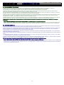
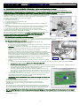
3.0G Sistema termostatico per la condensazione dei vapori di scarico: è composto di un
elettrovalvola, comandata da un termostato il cui sensore è alloggiato a contatto con lo scarico.
L’elettrovalvola tramite l’iniettore (G) provvede ad immettere acqua fredda nel tubo di scarico per
condensare il vapore quando viene raggiunta la temperatura di 90°C, (Fig. 3.0G).
3.0H Valvola sfiato camera: ha la funzione di regolare l’umidità all’interno della camera di cottura e viene attivata manualmente tramite il pommello
(A), situato sopra la porta. (Fig. 3.0H).
3.0I Sonda di temperatura al cuore: (fornita su richiesta nei modelli “Analogic” e di serie nei modelli “Electronic”) permette, tramite l’apposito
spillone da infilzare nel cibo da cuocere, l’esatto controllo della temperatura al cuore.
3.0L Valvola sicurezza gas: la valvola è corredata di un dispositivo elettronico di controllo che interrompe l’efflusso del gas entro 10” in caso di
mancata accensione dei bruciatori. L’operazione di accensione dei bruciatori potrà essere ripetuta previo il ripristino manuale del dispositivo
elettronico da eseguire tramite il pulsante (Z) posizionato nel cruscotto. (Fig. 3.0L)
3.0 CONTROL AND SAFETY DEVICES
The ovens are equipped with a set of control and safety devices for the electric and hydraulic circuits.
3.0A 2A fuse:
it is in the auxiliary circuit to protect against short circuiting of the electrical system and is inside its own support on the contactors
fixing bracket.
3.0B 1A fuse:
it is in the electronic controller’s electrical supply circuit, (“Electronic” versions) to protect against short circuiting and is housed inside
its own support on the contactors’ fixing bracket.
3.0C1 0,5A (500 mA) fuse:
security for electric fan 24V (only for gas version) placed in its own support on the premix circuit board.
3.0C2 2A fuse:
security for premix circuit board power supply 220V placed in its own support on the circuit board.
3.0D Motor overload protection:
a thermal probe disengages the motor when, for various reasons, there is an overload. When the overload
protection triggers it stops the motor and also disconnects the heating elements or the gas valve.
The probe is reset automatically when motor temperature drops.
3.0E Oven safety thermostat:
disconnects the heating element or the gas valve when anomalies related to overheating occur. Subsequent re-set
will have to be done manually when causes for thermostat operation have been determined.
3.0F Door microswitch, magnetic type:
it stops the oven working when the door is opened.
3.0G Thermostat system for condensation of discharge steam:
it comprises a solenoid valve controlled by a thermostat whose sensor is housed
in contact with the discharge. The solenoid valve, via the injector (G), lets cold water into the drainpipe to condense the steam when a temperature of
90°C is reached, (Fig. 3.0G).
3.0H Oven relief valve:
its job is to adjust humidity inside the cooking chamber . The valve is manually activated acting on the knob (A) (Fig.3.0H)on
top of the door.
3.0I Heart temperature probe:
(supplied on request with the “Analogic” models and a standard feature with the “Electronic” models) with a special
sensor inserted in the food to cook you can control the exact temperature right in the centre.
3.0L Gas safety valve:
the valve is fitted with an electronic control device that interrupts the flow of gas within 10 seconds if the burners fail to light.
Lighting of the burners can be repeated after the electronic device has been manually reset with the push button (Z) located on the control panel.
(See Fig. 3.0L)
Fig. 3.0G
Abb. 3.0G
La pagina si sta caricando...
La pagina si sta caricando...
La pagina si sta caricando...
-
 1
1
-
 2
2
-
 3
3
-
 4
4
-
 5
5
-
 6
6
-
 7
7
-
 8
8
-
 9
9
-
 10
10
-
 11
11
-
 12
12
-
 13
13
-
 14
14
-
 15
15
-
 16
16
-
 17
17
-
 18
18
-
 19
19
-
 20
20
-
 21
21
-
 22
22
-
 23
23
-
 24
24
-
 25
25
-
 26
26
-
 27
27
-
 28
28
-
 29
29
-
 30
30
-
 31
31
-
 32
32
-
 33
33


Whirlpool ADN 508 Guida d'installazione
- Categoria
- Forni
- Tipo
- Guida d'installazione
in altre lingue
- English: Whirlpool ADN 508 Installation guide
- français: Whirlpool ADN 508 Guide d'installation
- español: Whirlpool ADN 508 Guía de instalación
- Deutsch: Whirlpool ADN 508 Installationsanleitung
Documenti correlati
-
Whirlpool ADN 500 Guida d'installazione
-
Whirlpool ADN 553 Manuale utente
-
Whirlpool AGB 631/WP Guida d'installazione
-
-
-
-
-
-
Altri documenti
-
Hendi 225929 Manuale utente
-
Candy FPG 390 Manuale utente
-
Metos UV Plus 62/102/E Manuale utente
-
Bartscher PM8-9IE Manuale utente
-
Sony MSX-512N Manuale utente
-
-
Sony MSX-256S Manuale utente
-
Sony MSX-4GN Istruzioni per l'uso
-
Univex Double Rack Rotating Manuale del proprietario
-
Maico AWB 120 C Mounting And Operating Instructions