Univex Double Rack Rotating Manuale del proprietario
- Categoria
- Piani cottura
- Tipo
- Manuale del proprietario
Questo manuale è adatto anche per

Electrical and gas ovens for pastry and bread
RDRE
T11 - E11
Series 14
Instruction Manual


SUMMARY
Summary ................................................................................................................................................................. 1
Declaration Of Conformity ........................................................................................................................................ 3
General Warnings ..................................................................................................................................................... 4
Shipping .................................................................................................................................................................... 5
Unloading And Handling ........................................................................................................................................... 6
Technical Data And Identification ............................................................................................................................. 7
Volumes And Connections Of Electric Version Of Unit ............................................................................................ 8
Volumes And Connections Of Gas Version Of Unit ................................................................................................. 9
Electrical Data For Electric Version ........................................................................................................................ 10
Electrical Data For Gas Version ............................................................................................................................. 10
Water Connection For Both Versions ..................................................................................................................... 10
Room ...................................................................................................................................................................... 11
Positioning Of Electric Version................................................................................................................................ 12
Positioning Of Gas Version ..................................................................................................................................... 12
Electrical Connection .............................................................................................................................................. 13
Burner ..................................................................................................................................................................... 14
Water And Drain Connection .................................................................................................................................. 14
Steam Discharge Connection (1) ............................................................................................................................ 15
Exhaust Discharge Connection For Gas Version (2) .............................................................................................. 15
Air Flow Adjustment In Electrical And Gas Version ................................................................................................ 16
Commissioning ....................................................................................................................................................... 17
Instructions For Use ................................................................................................................................................ 18
Safety Instructions For The User ............................................................................................................................ 18
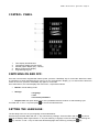
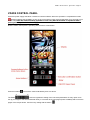
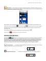
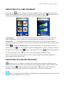
Control Panel 80P .................................................................................................................................................. 19
Switching On And Off:............................................................................................................................................. 19
Setting The Language: ............................................................................................................................................ 19
Setting The Time: ................................................................................................................................................... 20
Characteristics Of Programmes In Progress - Preheating And Baking Time Extension: ....................................... 20
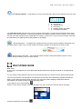
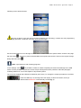
Manual Baking Mode: ............................................................................................................................................. 20
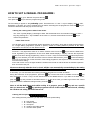
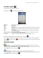
How To Set A Manual Programme: ........................................................................................................................ 21
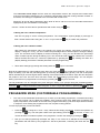
Programme Mode (Customizable Programming): .................................................................................................. 22
Executing A Customized Programme: .................................................................................................................... 23
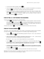
Preset Programmes: ............................................................................................................................................... 23
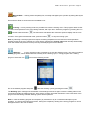
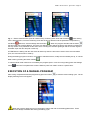
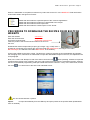
Vision Control Panel ............................................................................................................................................... 24
Settings Menu ......................................................................................................................................................... 25
Working Modes: ...................................................................................................................................................... 25
Manual Programming: ............................................................................................................................................ 27
Baking Parameters: ................................................................................................................................................ 28
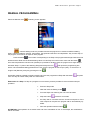
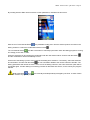
Multi-Timer Mode .................................................................................................................................................... 29
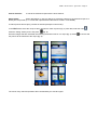
Execution Of A Manual Program ............................................................................................................................ 30
Execution Of A Chef Program ................................................................................................................................ 32
Execution Of A Recipe Program ............................................................................................................................. 32
Procedure To Download The Recipes From Bestfor Website ................................................................................ 34
Enabling Usb Menu ................................................................................................................................................. 36
Alarm Codes: .......................................................................................................................................................... 38
Cleaning And Care .................................................................................................................................................. 38
Causes Of Malfunction ........................................................................................................................................... 39
Technical Service.................................................................................................................................................... 40
Notes: ...................................................................................................................................................................... 40

RDRE - electric version - gas version - Page 2
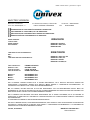
ELECTRIC VERSION
BAKE OFF ITALIANA SRL VIA CASTELBOLOGNESI,6 - ZONA P.M.I. TELEFONO 0532/732333
CAP. SOC. € 93.600,00 I.V. 44044 CASSANA / FERRARA FAX 0532/730589
DICHIARAZIONE DI CONFORMITÀ AI SENSI DELLE DIRETTIVE:
DECLARATION OF CONFORMITY TO THE DIRECTIVES:
DÉCLARATION DE CONFORMITÉ SUR LA BASE DES DIRECTIVES:
CERTIFICACIÓN DE CONFORMIDAD A LA DIRECTIVA:
BASSA TENSIONE: 2006/95/CE
LOW VOLTAGE:
BASSE TENSION: EN60335-2-42:2003
BAJA TENSIÒN: EN60335-1:2002; A11
EN50336:2003
COMPATIBILITÀ ELETTROMAGNETICA: 2004/108/CE
EMC:
EMC: EN55014-1:2000; A1; A2
COMPATIBILIDAD ELÈCTROMAGNETICA: EN55014-2:1997; A1
EN61000-3-2:2000
EN61000-3-3:1995; A1
TIPO DI PRODOTTO: FORNO ROTATIVO
PRODUCT TYPE: ROTARY OVEN
TYPE DE PRODUIT: FOUR ROTATIF
TIPO DE PRODUCTO: HORNO ROTATIVO
MODELLO: ROTORBAKE E11
MODEL: ROTORBAKE E11
MODÈL: ROTORBAKE E11
MODELO: ROTORBAKE E11
CON LA PRESENTE L’AZIENDA DICHIARA SOTTO LA PROPRIA RESPONSABILITÀ, CHE IL PRODOTTO SOPRACITATO SODDISFA PER
PROGETTAZIONE E COSTRUZIONE I REQUISITI DELLA DIRETTIVA “BASSA TENSIONE” E “COMPATIBILITÀ ELETTROMAGNETICA”. LA
CONFORMITÀ È STATA VERIFICATA CON L’AUSILIO DELLE SEGUENTI ARMONIZZATE:
WE, THE COMPANY, DECLARE HERE WITH ON OUR OWN RESPONSABILITY THAT THE ABOVE-MENTIONED PRODUCT MEETS THE
REQUIREMENTS OF THE LOW VOLTAGE DIRECTIVE FOR WHAT CONCERNS EMGINEERING AND CONSTRUCTION AND EMC CONFORMITY HAS
BEEN CONTROLLED WITH THE AID OF THE FOLLOWING HARMONIZED STANDARDS:
PAR LA PRÉSENTE NOUS DÉCLARONS SOUS MOTRE RESPONSABILITÉ QUE LA PRODUIT SOUS-INDIQUÉ, EN CE QUI CONCERNE SA
PROGETTATION ET FABRICATION EST CONFORME AUX CONDITIONS REQUISES PAR LA DIRECTIVE BASSE TENSION ET COMPATIBILITÉ
ELÉCTROMAGNETIQUE.
LA CONFORMITÉ A ÉTÉ VERIFIÉE A L’AIDE DES NORMES UNIFIÉES SUIVANTES:
CON ESTA LA EMPRESA DECLARA, POR SU MISMA RESPONSABILIDAD, QUE EL PRODUCTO CITADO ANTES ENCUENTRA LOS RECUISITOS DE
PROYETACION Y CONSTRUCCIÓN DE LA DIRECTIVA “BAJA TENSIÓN” Y “COMPATIBILIDAD ELÉCTROMAGNÉTICA”. LA CONFORMIDAD FUE
COMPROVADA CON LAS SIGUIENTES ARMONIZADAS STANDARD:
Ferrara, 20.04.2009 BAKE OFF ITALIANA S.R.L.
GIORGIO BORGHI

RDRE - electric version - gas version - Page 3
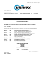
GAS VERSION
BAKE OFF ITALIANA SRL VIA CASTELBOLOGNESI,6 - ZONA P.M.I. TELEPHONE 0532/732333
SHARE CAPITAL € 93.600,00 FULLY PAID UP 44044 CASSANA / FERRARA FAX 0532/730589
DECLARATION OF CONFORMITY
DECLARATION OF CONFORMITY
89/392/CEE
WE HEREBY DECLARE ON OUR OWN EXCLUSIVE RESPONSIBILITY THAT THE PRODUCT:
MODEL : ROTOR T11
TO WHICH THIS DECLARATION REFERS IS COMPLIANT WITH THE FOLLOWING STANDARDS:
prEN XXX : 1994 STANDARD OF TYPE C ROTARY OVEN
EN292-1 : 1992 BASIC CONCEPTS, GENERAL PRINCIPLES OF
DESIGN, TERMINOLOGY, BASIC METHODOLOGY
EN292-2 : 1992 BASIC CONCEPTS, GENERAL PRINCIPLES OF
DESIGN, TECHNICAL PRINCIPLES AND SPECIFICATIONS.
EN294 : 1993 SAFETY DISTANCES FOR UPPER LIMBS.
PrEN 953 : 1992 DESIGN AND CONSTRUCTION OF PROTECTIONS.
PrEN 954-1 : 1992 PRINCIPLES OF DESIGN FOR TEST SYSTEMS
THAT AFFECT SAFETY
PrEN 563 : 1994 TOUCHABLE HOT SURFACES
EN 60204-1 : 1993 ELECTRICAL EQUIPMENT ON THE MACHINE
EN 60529 : 1991 COVERINGS AND DEGREE OF PROTECTION
ISO 468 : 1991 ROUGHNESS OF SURFACES
C.M. n°68 : 1969 METHANE HEATING SYSTEMS
C.M. n°73 : 1971 FUEL OIL HEATING SYSTEMS
AS SET FORTH BY DIRECTIVES
89/392/CEE
73/23/CEE
90/396/CEE
98/37/CEE
APPROVAL OF GAS-FIRED OVENS
DWGW N°CE 0085AR0301
BAKE OFF ITALIANA s.r.l.
GIORGIO BORGHI
Ferrara, 03.09.2001

RDRE - electric version - gas version - Page 4
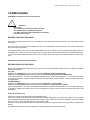
GENERAL WARNINGS
This manual must be delivered along with the appliance, and it must stay with it for the entire duration of the
appliance.
These instructions must be kept near the unit in an easily accessible place for easy reference over time.
Installation, commissioning and maintenance of the oven must be performed only by qualified personnel in
compliance with these manufacturer instructions and with the latest current standards.
No devices or safety devices must be moved, removed, disabled or interrupted, as this would void the
manufacturer's guarantee.
The unit must undergo scheduled maintenance by qualified personnel from the manufacturer.
The oven must be used only for its intended purpose, which is the cooking of all bread and pastry up to the
maximum sizes and weights compatible with the sizes of the pans and cooking chamber. Any other use is
to be considered improper.
It is not advisable to place products with a high alcohol content in the oven.
The oven must be used only by persons who have been properly trained in its use.
The cooking chamber and the inside of the unit need to be cleaned every day. This will safeguard
appearance, hygiene and proper operation.
Upon completion of use, all connections are to be cut off (electrical power, gas and water for those models
which include the latter).
Shut down the unit in the event of malfunction or failure.
Non-original spare parts may not ensure perfect operation and safety of the oven. Therefore, only by
contacting the manufacturer or manufacturer-authorized personnel can you be sure that the spare parts
and labour are of the required quality.

RDRE - electric version - gas version - Page 5
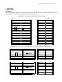
SHIPPING
TRANSPORT
The oven is normally shipped in a wood crate, open on the top and resting on a platform that can be set on a
pallet. The single pieces are protected and placed inside the oven.
Packaging of assembled oven with position of warnings
Side
Front
Address
Packaging for oven in two sections for closed container, with position of warnings
Address
Address

RDRE - electric version - gas version - Page 6
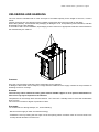
UNLOADING AND HANDLING
The oven must be unloaded with a crane and ropes of a suitable capacity for the weight of the oven, or with a
forklift.
Internal movement is to be carried out using a forklift or hand truck when the oven is still on the pallet.
When taking delivery, check whether the packaging is damaged. If it is, accept delivery with reservation, and take
photographs of any clear damage.
In accordance with current standards, all packaging must be turned in to appropriate collection centres based on
the materials they are made of.
CHECKING
Once the oven has been unpacked, check it thoroughly for any damage
If damage is discovered due to transport, comply with the conditions of the supply contract for the procedure for
obtaining economic coverage.
STORAGE
The oven may not be stacked on other goods without suitable support so as to prevent deformations. It
must not in any way be exposed to the elements.
Temperatures in the storage area must be between -10°C and 70°C. Humidity must be such that condensation
does not form.
The oven has a minimum degree of protection of IP44.
SHUTDOWN
For maintenance or during holidays, etc., do the following:
- Disconnect the supply of water and electrical energy.
- Ventilate the oven by leaving the door open. Cover the opening with a net with a mesh of not more than 5 mm
to keep harmful animals out of the oven.

RDRE - electric version - gas version - Page 7
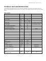
TECHNICAL DATA AND IDENTIFICATION
The essential technical data of the oven are shown on the data plate. All connections are marked on the oven.
When communicating with the manufacturer or the service centre, always provide the model, code and serial
number.
Gas version
Description
U.M.
Value
Notes
Weight
Kg
1600
Largest volume
Mm
155
0x2240
Cart max. diagonal
Mm
1150
Cart max. width
Mm
860
Pan
Cm
80x80 – 80x100
Cart max. load
Kg
200 / 200 / 400
Hook / platform / Reinf. Platf.
Cooking surface
M
2
11,5
18 pans 80x80 - 80x100
Hourly production (approximate)
Kg
195
Max. operating temperature
°C
300
Temperature increase gradient
°C/Min
12
Empty
Temperature increase gradient
°C/Min
6
With full load
Interval of humidification
Min
10
Oven temperature 200°
team discharge fan
Dm
3
/S
250
Fire box volume
Dm
3
/S
72
Installed electrical power
Kw
1.5
Thermal power
Kcal/H
65000
Pressure in fire box
Mbar
-1 -4
With burner on
Fuel oil
Kcal/Kg
10200
Methane gas fuel
Kcal/M
3
8500
LPG fuel
Kcal/Kg
11000
C.M.G. Fuel: heating oil
Kg/H
4
Approximate
C.M.G. Fuel: methane gas
M
3
/H
5
Approximate
Burner:
Type: Single stage blown air
Max length of nosepiece
Nozzle
Power supply voltage
Mm
Gph
V
120
1,75 A 60°
230
With pump calibrated at 12
bar

RDRE - electric version - gas version - Page 8
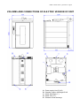
VOLUMES AND CONNECTIONS OF ELECTRIC VERSION OF UNIT
A - Power supply inlet (Pg 36)
B - Chamber vapour discharge Ø 140
C - Water discharge (1”)
D - Water inlet (¾”)
E – Extractor hood discharge

RDRE - electric version - gas version - Page 9
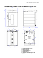
VOLUMES AND CONNECTIONS OF GAS VERSION OF UNIT
A - Power supply inlet (Pg 36)
B - Smoke discharge
C - Water discharge (1”)
D - Water inlet (¾”)
E - Chamber vapour discharge Ø 140
F - Extractor hood discharge
G -Burner

RDRE - electric version - gas version - Page 10
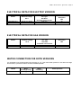
ELECTRICAL DATA FOR ELECTRIC VERSION
Model
Nominal voltage
AC V
Connection cable
min. type
H07 RN-F
minimum cross-section
Nominal
absorption
kW
RotorBake E11
208 3F VAC 60 HZ
4x35 mm²
50
400 3N VAC 50 HZ
5x10 mm²
50
ELECTRICAL DATA FOR GAS VERSION
Model
Nominal voltage
AC V
Connection cable
min. type
H07 RN-F
minimum cross-section
Nominal
absorption
kW
RotorBake T11
208 3F VAC 60 HZ
4x6 mm²
1.5
400V 3F+N VAC 50 HZ
5x4 mm²
1.5
WATER CONNECTION FOR BOTH VERSIONS
It is advisable to use softened water with hardness of 5°f. If the mains water pressure is not within the range
shown below, a pressure reducer must be installed upstream.
Model
Water
discharge fitting
Water
inlet fitting
Mains pressure
RotorBake E11-T11
1
/
2
“
¾ “
50 - 300 kPa

RDRE - electric version - gas version - Page 11
ROOM
The unit must be placed in a well-ventilated location, if possible under an exhaust hood to ensure rapid removal
of cooking vapours. Comply with requirements on free cross-section for drawing combustion air and for the
removal of any gas leaks.
The temperature in the place of installation must not exceed values of less than + 5° C or more than + 40° C. The
air humidity must be within the range of 40% to 75%. Conditions other than these may have a negative effect on
the unit's operation.
The oven must be levelled.
This can be checked wither with a spirit level or by setting a pan on top that has a small amount of water in it.
The backs and sides must be 10 cm from other appliances and flammable walls. If the distance is less or the
position is next to other units that give off heat (e.g. fryers), appropriate measures must be taken such as placing
protection against radiance
The manufacturer suggests a distance of 50 cm to allow for cleaning and service.
Make sure the openings of the unit are not obstructed or covered!
Strict compliance with fire prevention measures must be ensured

RDRE - electric version - gas version - Page 12
POSITIONING OF ELECTRIC VERSION
!
Attention!
During positioning and installation, ensure compliance with the following prescriptions, technical rules
and directives:
- current legal requirements
- local building and fire codes
- accident prevention requirements
- directives and regulations of the provider of electrical energy
- current CEI regulations
- building directives for fire prevention techniques for ventilation systems
- any special local requirements
- workplace requirements
- rules for kitchen safety
- Interior Ministry Circular no. 68 dated 25.11.1959 and subsequent variations, "Standards of safety for
mains-connected heating systems"
- Current standards for chimneys and connections
- directives on ventilation systems for kitchens
POSITIONING OF GAS VERSION
!
Attention!
During positioning and installation, ensure compliance with the following prescriptions, technical rules
and directives:
- current legal requirements
- local building and fire codes
- Law no. 1083 dated 06.12.71 “Standards of safety for the use of combustible gas"
- Circular letter no. 412/4183 dated 06.05.75 “Standards of safety for kitchen systems fuelled by LPG"
- Standards UNI - CIG 7129/72 “Standards gas systems supplied by the LPG distribution system"
- accident prevention requirements
- directives and regulations of the provider of gas
- directives and regulations of the provider of electrical energy
- current CEI regulations
- building directives for fire prevention techniques for ventilation systems
- any special local requirements
- workplace requirements
- rules for kitchen safety
- Law no. 1083 dated 06.12.71 “Standards of safety for the use of combustible gas"
- Interior Ministry Circular no. 68 dated 25.11.1959 and subsequent variations, "Standards of safety for
mains-connected heating systems"
- Current standards for chimneys and connections
- directives on ventilation systems for kitchens
Remove protective film from the outer panels of the oven by detaching it slowly. Make sure to remove any
residues of adhesives. Residual adhesive can be removed using suitable products such as stain remover

RDRE - electric version - gas version - Page 13
ELECTRICAL CONNECTION
!
Attention!
The electrical connection must be made only by qualified personnel. It must be in compliance with CEI
requirements and specifications.
Check the setup of the oven. Compare the data for the available mains voltage and current with the information
on the data plate. The electrical diagram is included with this manual.
The unit must be connected to the mains only if between it and the mains there is an omnipolar switch with at
least 3 mm of opening between contacts for each pole. This must be in an easily accessible position near the
oven.
The connection cable must be at least type H07 RN-F. The minimum cross-section and the number of wires are
shown in the table "Electrical Data". Fixed connections require the use of conduits which must comply with
standards.
Remove the cover of the electrical panel, insert the cable in the cable clamp and connect the single wires to the
corresponding terminal. The plate near the terminal block shows the correct positions of the phases.
After connecting the cable to the terminal block, tighten the cable clamp and close again.
Electrical safety is ensured only when the unit is properly earthed as required by current standards.
The oven is also to be included in an efficient equipotential system. This connection is made with the terminal
marked with the symbol located on the back of the unit.
!
Attention!
Connection to the gas mains must be carried out only by specialized personnel with a valid license to do
so. The manufacturer shall not be held liable if this requirement is not complied with.
The oven belongs to category II
2H3+
. This means it is suitable for operation with the following gases and at the
following pressures:
Methane H 20 mbar
LPG 28-30/37 mbar
Connection may be made only after receiving approval from the energy provider.
Connection to gas pipes may be permanent, or it may be possible to disconnect it by installing upstream a cock
with certified closing. The cock must be in an easily accessible position near the oven.
If hoses are used, they must be made of stainless steel, and they must comply with applicable standards. It is
severely prohibited to reduce the diameter of the gas inlet.
Once connection is complete, check the seals with a leak detection spray that does not cause corrosion.
It is absolutely prohibited to use open flames!

RDRE - electric version - gas version - Page 14
BURNER
!
See the specific requirements provided by the manufacturer.
Installation, calibration, testing and guarantee documentation are all provided by the nearest service centre
designated by the manufacturer of the burner.
Before making connections, check that the burner is compatible with the provided fuel.
Attach the burner to the flange above the oven after inserting the gasket of insulating material that is included in
the packaging.
To prevent possible gas leaks, it is advisable to use a gas detector connected to a cut-off valve which, if required,
interrupts the flow.
WATER AND DRAIN CONNECTION
There must be a tap to close the water supply between the units and the water mains. The fitting upstream for
the water connection must be compliant with current requirements. The water connection fitting is located on the
back of the unit and is duly marked.
Information on acceptable water pressure is shown in the paragraph "Water Connection".
It is advisable to connect to a source with softened water, with a degree of hardness between 2 and 5° fH.
It is advisable to use a hose that is capable of absorbing small changes in pressure.
Before making the connection, let water run out of the pipes.
The drain should be made using rigid, heat-resistant pipe (maximum length 2 m). Drain water is to be carried to
the drain system in a constant flow with a funnel or siphon. It is prohibited to reduce the diameter of the pipe.
!
Attention!
A drain which is not properly constructed may release unpleasant odours into the cooking chamber!

RDRE - electric version - gas version - Page 15
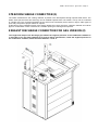
STEAM DISCHARGE CONNECTION (1)
The steam released from the cooking chamber is placed in the atmosphere through special steam ducts. The
steam ducts (exhaust hood and chimney) can be installed separate from one another, or they can be combined
in a single duct. The connection between the two ducts must necessarily be as shown in figure. Other types of
joints may compromise proper release of vapours.
At the base of every upwards section of the steam release duct, there must be a collection chamber and a drain
pipe for condensation. There must also be a suitable opening for cleaning and inspection.
EXHAUST DISCHARGE CONNECTION FOR GAS VERSION (2)
The length and shape of the discharge pipe affects the negative pressure in the combustion chamber. It
is advisable to run the pipes upwards for at least 2 metres. Nonetheless, check the negative pressure in
the combustion chamber, which should be between -1 and -4.

RDRE - electric version - gas version - Page 16
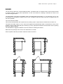
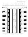
AIR FLOW ADJUSTMENT IN ELECTRICAL AND GAS VERSION
To obtain precise distribution and even cooking, adjust the air flow outlet shutters as follows:
Loosen the M8 nuts that hold the shutters inside the oven. Adjust the opening of the shutters as shown in the
table below. Tighten the nuts. Make sure that while doing so, the opening as in the table below is maintained.
10mm
10mm
11mm
11mm
11mm
11mm
13mm
13mm
13mm
13mm
15mm
15mm
15mm
15mm
17mm
17mm
17mm
17mm
18mm
18mm
18mm
18mm
21mm
21mm
The above adjustments are those which are best for even cooking. If they are changed by unskilled or
unauthorized persons, this work is not covered by the guarantee.

RDRE - electric version - gas version - Page 17
COMMISSIONING
PRELIMINARY OPERATIONS FOR ELECTRIC VERSION
!
Attention!
check that:
- all connections have been made correctly
- the film has been completely removed
- the main electrical switch upstream is activated
- the water tap is open
INSTRUCTIONS FOR THE USER
The oven may be delivered to the user only after all of the work and checks described in this manual have been
performed.
The use of the oven must be fully explained to the user, especially as concerns safety. This must be done with
the aid of these instructions.
It should be pointed out to the user that modifications to the room where the unit is installed may affect the flow of
combustion air. Therefore, this would require the unit's operation to be checked again by a specialized technician.
The client should be advised to take out a service contract, since this type of unit requires at least one check per
year.
PRELIMINARY OPERATIONS FOR GAS VERSION
INSTRUCTIONS FOR THE USER
Refer to the supplementary tag on the back of the oven to check admissible mains pressure for proper operation,
which are as follows:
For LPG:
Operation is permitted for a range of mains pressure between 20/25 and 35/45 mbar,
Operation is not permitted with mains pressure less than 20/25 and greater than 35/45 mbar.
If the mains pressure in the place of installation is different from what is indicated above, or is not within the range
of pressure, advise the system installer and do not commission the system until the cause has been discovered
and eliminated.
For METHANE H:
Operation is permitted for a range of mains pressure between 17 and 25 mbar,
Operation is not permitted with mains pressure less than 17 and greater than 25 mbar.
If the mains pressure in the place of installation is different from what is indicated above, or is not within the range
of pressure, advise the provider and do not commission the system until the cause has been discovered and
eliminated.
CHECK OF THERMAL YIELD
Checking the thermal yield consists of the following points:
First of all, compare the data on the data plate and supplementary plate concerning the category of the unit and
the gas adjustment with the gas provided at the location (type of gas and connection pressure). If this information
does not match, check correspondence of burner/type of gas.
The unit is to be commissioned with the given nominal yield, the required nozzle and the primary air adjustment
device.
An additional check of the nominal capacity can be provided by the volumetric method.

RDRE - electric version - gas version - Page 18
Cart
Insertion
- Set the time for the humidification cycle.
- Completely open the door.
- Check that the steam extractor starts working.
- Push the cart into the oven until the upper bearing of the cart enters the housing of the hook.
- Close again, and turn the door handle clockwise until it is locked horizontally.
Extraction
- An acoustic signal will advise you that the set cooking time has expired.
- Begin taking the products out of the oven as follows:
- Release the door, and leave it ajar for a few moments. This will allow any residual steam to be extracted.
- Now open the door completely. Using heat resistant gloves, extract the cart.
- Close again, and turn the door handle clockwise until it is locked horizontally.
INSTRUCTIONS FOR USE
SAFETY INSTRUCTIONS FOR THE USER
!
Attention!
Only after completing all connections, the unit is ready for commissioning.
The unit can be safely operated only if the following instructions are adhered to.
The user may use this appliance only after he has been properly instructed on its use and operation.
Coverings or parts of the unit which can only be removed with the aid of a tool must absolutely not be
removed.
The unit must be monitored while in use.
During operation, the door becomes hot. Be very careful with it.
Be very careful when opening the door during operation or when the unit is hot, as hot vapours may be
released by it!
Protect the unit from freezing temperatures.
All work concerning installation or repair of the unit are to be performed by qualified personnel in
compliance with current standards.
At least once a year, have the unit checked by qualified personnel from the manufacturer. For this
purpose we suggest stipulating a service contract.
The unit must be cleaned on a daily basis.
The unit is not protected against splashes of water. Therefore, do not use direct or pressurized jets of
water
Note: The noise level at in the workplace is less than 70 dB (A). This information is required for certain
national safety standards.
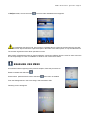
Delayed start: allows the operator to perform start-up and hence the pre-heating phase at a certain time by
setting the day and time using the programming knob. Enter the menu to set in order the day of the week, start-
up time and enabling.
La pagina si sta caricando...
La pagina si sta caricando...
La pagina si sta caricando...
La pagina si sta caricando...
La pagina si sta caricando...
La pagina si sta caricando...
La pagina si sta caricando...
La pagina si sta caricando...
La pagina si sta caricando...
La pagina si sta caricando...
La pagina si sta caricando...
La pagina si sta caricando...
La pagina si sta caricando...
La pagina si sta caricando...
La pagina si sta caricando...
La pagina si sta caricando...
La pagina si sta caricando...
La pagina si sta caricando...
La pagina si sta caricando...
La pagina si sta caricando...
La pagina si sta caricando...
La pagina si sta caricando...
La pagina si sta caricando...
La pagina si sta caricando...
-
 1
1
-
 2
2
-
 3
3
-
 4
4
-
 5
5
-
 6
6
-
 7
7
-
 8
8
-
 9
9
-
 10
10
-
 11
11
-
 12
12
-
 13
13
-
 14
14
-
 15
15
-
 16
16
-
 17
17
-
 18
18
-
 19
19
-
 20
20
-
 21
21
-
 22
22
-
 23
23
-
 24
24
-
 25
25
-
 26
26
-
 27
27
-
 28
28
-
 29
29
-
 30
30
-
 31
31
-
 32
32
-
 33
33
-
 34
34
-
 35
35
-
 36
36
-
 37
37
-
 38
38
-
 39
39
-
 40
40
-
 41
41
-
 42
42
-
 43
43
-
 44
44


Univex Double Rack Rotating Manuale del proprietario
- Categoria
- Piani cottura
- Tipo
- Manuale del proprietario
- Questo manuale è adatto anche per
in altre lingue
Altri documenti
-
Unox BakerTop Manuale utente
-
Foster S4000 Manuale utente
-
Foster Oven Manuale utente
-
Sanyo MPR-1411 Manuale utente
-
Sanyo MDF-U74VC Manuale utente
-
Hobart HFEI D Series Installation, Use And Maintenance Instructions
-
Alfa Network Zeno Manuale utente
-
Whirlpool ADN 510 Guida d'installazione
-
-
Firex betterpan DBRG...-C series Owner's Instruction Manual