
1
http://www.tyan.com
S7012
Version 1.1
Copyright
Copyright © 2009 MiTAC International Corporation. All rights reserved. TYAN
®
is a
registered trademark of MiTAC International Corporation.
Trademark
All registered and unregistered trademarks and company names contained in this
manual are property of their respective owners including, but not limited to the
following.
TYAN
®
is a trademark of MiTAC International Corporation.
Intel
®
Nehalem-EP Series and combinations thereof are trademarks of Intel
Corporation.
AMI, AMI BIOS are trademarks of AMI Technologies.
Microsoft, Windows are trademarks of Microsoft Corporation.
SuSE is a trademark of Novell.
IBM, PC, AT, and PS/2 are trademarks of IBM Corporation.
Notice
Information contained in this document is furnished by MiTAC International
Corporation and has been reviewed for accuracy and reliability prior to printing.
MiTAC assumes no liability whatsoever, and disclaims any express or implied
warranty, relating to sale and/or use of TYAN products including liability or
warranties relating to fitness for a particular purpose or merchantability. MiTAC
retains the right to make changes to product descriptions and/or specifications at
any time, without notice. In no event will MiTAC be held liable for any direct or
indirect, incidental or consequential damage, loss of use, loss of data or other
malady resulting from errors or inaccuracies of information contained in this
document.

2
http://www.tyan.com
Table of Contents
Check the box contents! 3
Chapter 1: Introduction
1.1 Congratulations 5
1.2 Hardware Specifications 5
1.3 AST2050 Application 6
Chapter 2: Board Installation
2.1 Board Image 8
2.2 Block Diagram 9
2.3 Board Parts, Jumpers and Connectors 10
2.4 Installing the Processor and Heatsink 20
2.5 Thermal Interface Material 23
2.6 Finishing Installing the Heatsink 24
2.7 Tips on Installing Motherboard in Chassis 25
2.8 Installing the Memory 26
2.9 Attaching Drive Cables 29
2.10 Installing Add-in Cards 30
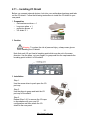
2.11 Installing I/O Shield 31
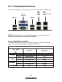
2.12 Connecting External Devices 32
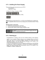
2.13 Installing the Power Supply 33
2.14 Finishing up 33
Chapter 3: BIOS Setup
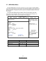
3.1 BIOS Main Menu 37
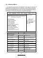
3.2 Advanced Menu 38
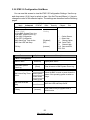
3.3 PCI PnP Menu 64
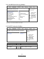
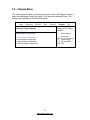
3.4 Boot Menu 66
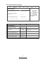
3.5 Security Menu 70
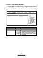
3.6 Chipset Menu 71
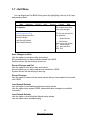
3.7 Exit Menu 76
Chapter 4: Diagnostics
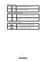
4.1 Beep Codes 77
4.2 Flash Utility 77
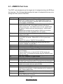
4.3 AMI BIOS Post Code 78
Glossary
81
Technical Support
87

3
http://www.tyan.com
Check the box contents!
1x S7012 motherboard
2 x mini SAS Cable (optional)
6 x Serial ATA Cable
1 x USB2.0 cable
1 x S7012 User’s Manual
1 x S7012 Quick Reference Guide
1 x I/O Shield Installation Guide
1 x TYAN Installation CD
1 x I/O shield
If any of these items are missing, please contact your vendor/dealer for
replacement before continuing with the installation process.

4
http://www.tyan.com
NOTE

5
http://www.tyan.com
Chapter 1: Introduction
1.1 - Congratulations
You have purchased one of the most powerful server solutions. Based on Intel
®
5520 and ICH10R chipsets, the S7012 is designed to support up to two Nehalem-
EP Series processors and up to 144GB DDR3-800/1033/1066/1333 memory,
providing a rich feature set and incredible performance. Leveraging advanced
technology from Intel, the S7012 is capable of offering scalable 32 and 64-bit
computing, high-bandwidth memory design, and lightning-fast PCI-E bus
implementation.
The S7012 not only empowers your company in today’s demanding IT environment
but also offers a smooth path for future application usage. All of this provides the
S7012 the power and flexibility to meet the needs of nearly any server application.
Remember to visit TYAN’s Website at http://www.tyan.com. There you can find
information on all of TYAN’s products with FAQs, online manuals and BIOS
upgrades.
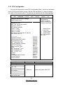
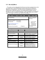
1.2 - Hardware Specifications
Supported CPU Series
Intel Xeon Processor 5500 Series
Socket Type / Q'ty LGA1366 / (2)
Thermal Design
Power (TDP) wattage
Max up to 130W
Processor
System Bus
Up to 4.8/ 5.86/ 6.4GT/s with Intel QuickPath Interconnect
(QPI) support
IOH / ICH Intel 5520 / ICH10R
Chipset
Super I/O Winbond W83627DHG
Supported DIMM Qty (18) DIMM slots
DIMM Type / Speed
DDR3 800/1066/1333* RDIMM/UDIMM / * limit 1 per
channel for 1333MHz speed
Capacity Up to 144GB at launch w/ dual rank RDIMMs
Memory channel 3 Channels per CPU
Memory
Memory voltage 1.5V
Expansion
Slots
PCI-E (1) PCI-E x8 slot (w/ x4 link) / (4) PCI-E Gen.2 x8 slots
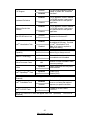
Port Q'ty (4)
LAN
Controller Intel 82574L / Intel 82576EB
Connector (2) Mini-SAS connectors (totally support 8 ports)
Controller LSI SAS1068E
Speed 3.0 Gb/s
SAS
(optional)
RAID RAID 0/1/1E (LSI Integrated RAID)
Connector (6) SATA
Controller ICH10R
Speed 3.0 Gb/s
Storage
SATA
RAID RAID 0/1/10/5 (Intel Matrix RAID)
Graphic Connector type D-Sub 15-pin

6
http://www.tyan.com
Resolution 1600x1200@60Hz
Chipset Aspeed AST2050
USB (7) USB2.0 ports (4 at rear, 2 via cable, 1 type A onboard)
COM (1) port (rear)
SAS (2) Mini-SAS (4-in-1) connectors
VGA (1) D-Sub 15-pin VGA port
RJ-45 (4) GbE ports
Power SSI 24-pin + 8-pin + 8-pin power connectors / EPS12V
Front Panel (1) 2x12-pin SSI front panel header
Input /Output
SATA (6) SATA-II connectors
Chipset Winbond W83793G
Voltage Monitors voltage for CPU, memory, chipset & power supply
Fan Total (5) 4-pin headers / Total (5) 8-pin headers
Temperature Monitors temperature for CPU & system environment
System
Monitoring
Others Chassis intrusion detection / Watchdog timer support
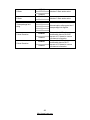
Onboard Chipset Onboard Aspeed AST2050
AST2050 IPMI
Feature
IPMI 2.0 compliant baseboard management controller
(BMC) / Supports storage over IP and remote platform-
flash/ BIOS update / USB 2.0 virtual hub
Server
Management
AST2050 iKVM
Feature
24-bit high quality video compression / Dual 10/100 Mb/s
MAC interfaces
Brand / ROM size AMI / 4MB
BIOS
Feature
Plug and Play (PnP) /PCI2.3 /WfM2.0 /SMBIOS2.3 /PXE
boot / ACPI 2.0 power management /Power on mode after
power recovery / User-configurable H/W monitoring / Auto-
configurable of hard disk types / Multiple boot options
Form Factor SSI EEB
Form Factor
Board Dimension 12"x13" (305x330mm)
Operating
System
OS supported list
Please refer to our OS supported list.
http://www.tyan.com/tech/os_support1.aspx
FCC (DoC) Class B
Regulation
CE (DoC) Yes
Operating Temp. 10° C ~ 35° C (50° F~ 95° F)
Non-operating Temp. - 40° C ~ 70° C (-40° F ~ 158° F)
Operating
Environment
In/Non-operating
Humidity
90%, non-condensing at 35° C
RoHS RoHS 6/6 Complaint Yes
Motherboard (1) S7012 Motherboard
Manual (1) User's manual / (1) Quick Ref. Guide (1) IO Shield QR
Installation CD (1) TYAN installation CD
I/O Shield (1) I/O Shield
SATA (6) SATA signal cables
SAS (2) Mini-SAS (2x SFF-8470) cables
Package
Contains
Cable
USB (1) CCBL-035J, 2-port USB bracket cable
Riser Card M2091, PCI-E 1U riser card (left)
Optional
accessories for
future
upgrade
Cable
(1) CCBL-0615, COM port bracket cable / (1) CCBL-0311,
SATA 1-to-2 power cable / (1) CCBL-035J, 2-port USB
bracket cable
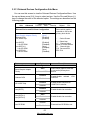
1.3 - AST2050 Application
Please visit the TYAN Web Site at http://www.tyan.com to download the latest
AST2050 User’s Guide.

7
http://www.tyan.com
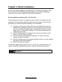
Chapter 2: Board Installation
You are now ready to install your motherboard. The mounting hole pattern of the
S7012 matches the SSI EEB specification. Before continuing with installation,
confirm that your chassis supports an SSI EEB motherboard.
How to install our products right… the first time
The first thing you should do is reading this user’s manual. It contains important
information that will make configuration and setup much easier. Here are some
precautions you should take when installing your motherboard:
(1) Ground yourself properly before removing your motherboard from the
antistatic bag. Unplug the power from your computer power supply and
then touch a safely grounded object to release static charge (i.e. power
supply case). For the safest conditions, TYAN recommends wearing a
static safety wrist strap.
(2) Hold the motherboard by its edges and do not touch the bottom of the
board, or flex the board in any way.
(3) Avoid touching the motherboard components, IC chips, connectors,
memory modules, and leads.
(4) Place the motherboard on a grounded antistatic surface or on the antistatic
bag that the board was shipped in.
(5) Inspect the board for damage.
The following pages include details on how to install your motherboard into your
chassis, as well as installing the processor, memory, disk drives and cables.
NOTE
DO NOT APPLY POWER TO THE BOARD IF IT HAS BEEN
DAMAGED.

8
http://www.tyan.com
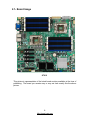
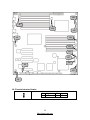
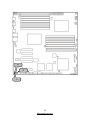
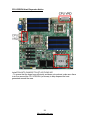
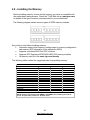
2.1- Board Image
S7012
This picture is representative of the latest board revision available at the time of
publishing. The board you receive may or may not look exactly like the above
picture.

9
http://www.tyan.com
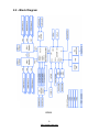
2.2 - Block Diagram
S7012

10
http://www.tyan.com
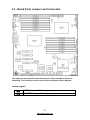
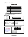
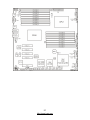
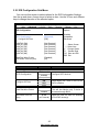
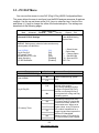
2.3 - Board Parts, Jumpers and Connectors
This diagram is representative of the latest board revision available at the time of
publishing. The board you receive may not look exactly like the above diagram.
Jumper Legend
OPEN - Jumper OFF, without jumper cover
CLOSED – Jumper ON, with jumper cover

11
http://www.tyan.com
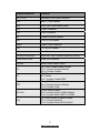
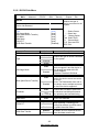
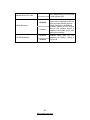
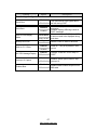
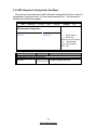
Jumper/Connector Function
J9 (TYFP1) Standard Front Panel Connector
J16 BMC I
2
C Bus Header
J34 USB Front Panel Header (blue)
J18 COM2 Connector
J24 PSMI Connector
J6 Chassis Intrusion Header
J35 CPLD JTAG Header
USB3 Type-A USB Connector
J33 ICH SGPIO Header
J15 Port 80 Header
J41/J42/J43/J44/J45 8-pin 4056 Fan Connector (reserved for BB)
J2/J8/J36/J37/J38 4-pin Fan Connector
J39/J40 Reset Switch/Power Switch
J3
LSI 1068E Enable/Disable Jumper
Pin 1-2 closed: Enable (Default)
Pin 2-3 closed: Disable
J7
BMC Reset Jumper
NC: Default
Pin 1-2 closed: Disable BMC
JP3
Clear CMOS Jumper
Pin 1-2 closed: Normal (Default)
Pin 2-3 closed: Clear
JP1/JP2
COM2 Switch Jumper
Pin 1-2 closed: SIO to COM2 (Default)
Pin 2-3 closed: BMC UART2 to COM2
JP4
LSI 1068E Device ID Select Jumper
Pin 1-2 closed: (Default)
Pin 2-3 closed: Device ID bit [0]=0b1

12
http://www.tyan.com
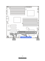
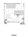
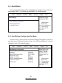
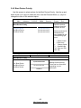
J18
(From left to right)
SATA5/SATA4/SATA3/SATA2/SATA1/SATA0
J34
J16
J15

13
http://www.tyan.com
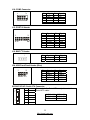
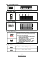
J18: COM2 Connector
1
2
1
0
9
Pin Signal Pin Signal
1 DCD 2 DSR
3 RXD 4 RTS
5 TXD 6 CTS
7 DTR 8 RI
9 GND 10 KEY
J15: PORT 80 Header
1
2
1
3
1
4
Pin Signal Pin Signal
1 NC 2 V3P3
3 NC 4 FRAME
5 CLK_33M 6 GND
7 GND 8 LAD3
9 PLTRST 10 LAD2
11 NC 12 LAD1
13 NC 14 LAD0
J16: BMC I
2
C Header
1
Pin Signal Pin Signal
1 IPMB_DAT 2 GND
3 IPMB_CLK 4 NC
J34: USB Front Panel Header (Blue)
10
9
2
1
Pin Signal Pin Signal
1 +5V 2 +5V
3 USB D- 4 USB D-
5 USB D+ 6 USB D+
7 GND 8 GND
9 KEY 10 GND
SATA0/1/2/3/4/5: Serial ATA Connector
7 GND
6 RXP
5 RXN
4 GND
3 TXN
2 TXP
7
1
1 GND
Connects to the Serial ATA ready drives via the
Serial ATA cable.
SATA0: J30 SATA1: J29
SATA2: J26 SATA3: J23
SATA4: J22 SATA5: J21

14
http://www.tyan.com
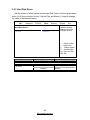
J6: Chassis Intrusion Header
1
Pin Signal Pin Signal
1 INTRUDER# 2 GND
J24
J38
J36
J9
J37
J8
J2
J6
J41
J42
J43
J44
J45

15
http://www.tyan.com
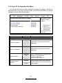
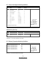
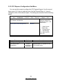
J9 (TYFP1): Standard Front Panel Connector
24
23
2
1
NOTE1: +3.3V power rail is IDLED, WLED (Warning LED), LANLED
NOTE2: +5V power rail is PWRLED, HDLED
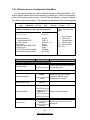
J24: PSMI Connector
1
Pin Signal Pin Signal
1 SMB_CLK 2 SMB_DAT
3 SMBALERT 4 GND
5 V3P3
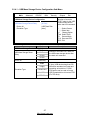
J2/J8/J36/J37/J38: 4-pin Fan Header
+12V
PWM Control
GND
Tachometer
1
+12V
PWM Control
GND
Tachometer
1
Use this header to connect the cooling
fan to your motherboard to keep the
system at optimum performance levels.
J2: Rear 1 FAN
J8: CPU0FAN
J36: Front 2 FAN
J37: Front 1 FAN
J38: CPU1FAN
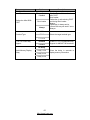
J41/J42/J43/J44/J45: 8-pin 4056 Fan Header (reserved for barebone)
J41: Sys5 FAN & Sys10 FAN
J42: Sys4 FAN & Sys9 FAN
J43: Sys3 FAN & Sys8 FAN
J44: Sys2 FAN & Sys7 FAN
J45: Sys1 FAN & Sys6 FAN
Pin Signal Pin Signal
1 PWM1 2 +12V
3 TACH1 4 GND
5 GND 6 TACH2
7 +12V 8 PWM2
PIN1 PIN3 PIN5 PIN7
PWRLED+ KEY PWRLED- HDLED+
PIN2 PIN4 PIN6 PIN8
+5VSB IDLED+ IDLED- WLED-
PIN9 PIN11 PIN13 PIN15
HDLED- PWRSW+ GND RSTSW
PIN10 PIN12 PIN14 PIN16
PSI_BMC_R- LAN1LED+ LAN1LED- SMBDAT
PIN17 PIN19 PIN21 PIN23
GND IDLED_SW TEMP-SENSOR NMI_SW-
PIN18 PIN20 PIN22 PIN24
SMBCLK INTRD# LAN2LED+ LAN2LED-

16
http://www.tyan.com
J35
USB3 J33
JP3
JP2
JP1

17
http://www.tyan.com
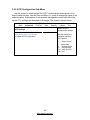
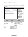
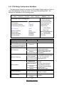
USB3: Type-A USB Connector
Pin Signal Pin Signal
1 +5V 2 USB D-
3 USB D+ 4 GND
J33: ICH SGPIO Header
1
0
2
9
1
Pin Signal Pin Signal
1 SMBCLK 2 SDATAOUT0
3 SMBDAT 4 SDATAOUT1
5 GND 6 SLOAD
7 KEY 8 SCLOCK
9 NC 10 NC
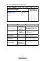
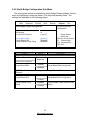
J35: CPLD JTAG Header
1
0
9
2
1
Pin Signal Pin Signal
1 JTAG_TCK 2 GND
3 JTAG_TDO 4 +3.3V
5 JTAG_TMS 6 NC
7 NC 8 KEY
9 JTAG_TDI 10 GND
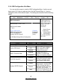
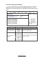
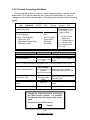
JP3: Clear CMOS Jumper
3
1
Normal
(Default)
1
3
Clear
Use this jumper when you forgot your system/setup
password or need to clear system BIOS setting.
How to clear the CMOS data
- Power off system and disconnect power
supply from AC source
- Use jumper cap to close Pin_2 and 3 for
several seconds to Clear CMOS
- Replace jumper cap to close Pin_1 and 2
Reconnect power supply to AC source
Power on system
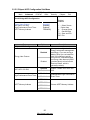
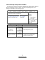
JP1/JP2: COM2 Switch Jumper
3
1
Pin 1-2 Closed: SIO to COM2 (Default)
1
3
Pin 2-3 Closed: BMC UART2 to COM2`

18
http://www.tyan.com
J1
J7
J3

19
http://www.tyan.com
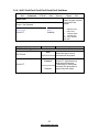
J7: BMC Reset Jumper
1
Pin 1-2 Open: Enable BMC(Default)
1
Pin 1-2 Closed: Disable BMC
J1: LSI 1068E Device ID Select Jumper
1
3
Pin 1-2 Closed: LSI 1068E Device ID (Default)
1
3
Pin 2-3 Closed: :LSI 1068E Device ID – Device ID bit
[0] =0b1
J3: LSI 1068E Enable/Disable Jumper
3
1
Pin 1-2 Closed: Enable LSI 1068E (Default)
1
3
Pin 2-3 Closed: Disable LSI 1068E

20
http://www.tyan.com
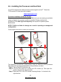
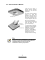
2.4 - Installing the Processor and Heat Sink
Your S7012 supports the latest processor technologies from Intel
®
. Check the
TYAN website for latest processor support:
http://www.tyan.com
Processor Installation (LGA1366 Socket)
The processor should be installed carefully. Make sure you are wearing an antistatic
strap and handle the processor as little as possible. Please note that both
processors of the same type and frequency are required for optimal system
performance.
NOTE: TYAN is not liable for damage as a result of operating an unsupported
configuration.
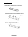
Follow these instructions to install your processor.
The diagram is provided as a visual guide to help you install the socket processor
and may not be an exact representation of the processor you have.
Step 1: Take off the CPU protection cap.
Step 2: Pull the CPU lever up to unlock the CPU socket (A). Then open the
socket in the direction as shown (B).
Step 3: Place the CPU on the CPU socket, ensuring that pin 1 is located in the
right direction.
La pagina si sta caricando...
La pagina si sta caricando...
La pagina si sta caricando...
La pagina si sta caricando...
La pagina si sta caricando...
La pagina si sta caricando...
La pagina si sta caricando...
La pagina si sta caricando...
La pagina si sta caricando...
La pagina si sta caricando...
La pagina si sta caricando...
La pagina si sta caricando...
La pagina si sta caricando...
La pagina si sta caricando...
La pagina si sta caricando...
La pagina si sta caricando...
La pagina si sta caricando...
La pagina si sta caricando...
La pagina si sta caricando...
La pagina si sta caricando...
La pagina si sta caricando...
La pagina si sta caricando...
La pagina si sta caricando...
La pagina si sta caricando...
La pagina si sta caricando...
La pagina si sta caricando...
La pagina si sta caricando...
La pagina si sta caricando...
La pagina si sta caricando...
La pagina si sta caricando...
La pagina si sta caricando...
La pagina si sta caricando...
La pagina si sta caricando...
La pagina si sta caricando...
La pagina si sta caricando...
La pagina si sta caricando...
La pagina si sta caricando...
La pagina si sta caricando...
La pagina si sta caricando...
La pagina si sta caricando...
La pagina si sta caricando...
La pagina si sta caricando...
La pagina si sta caricando...
La pagina si sta caricando...
La pagina si sta caricando...
La pagina si sta caricando...
La pagina si sta caricando...
La pagina si sta caricando...
La pagina si sta caricando...
La pagina si sta caricando...
La pagina si sta caricando...
La pagina si sta caricando...
La pagina si sta caricando...
La pagina si sta caricando...
La pagina si sta caricando...
La pagina si sta caricando...
La pagina si sta caricando...
La pagina si sta caricando...
La pagina si sta caricando...
La pagina si sta caricando...
La pagina si sta caricando...
La pagina si sta caricando...
La pagina si sta caricando...
La pagina si sta caricando...
La pagina si sta caricando...
La pagina si sta caricando...
La pagina si sta caricando...
La pagina si sta caricando...
-
 1
1
-
 2
2
-
 3
3
-
 4
4
-
 5
5
-
 6
6
-
 7
7
-
 8
8
-
 9
9
-
 10
10
-
 11
11
-
 12
12
-
 13
13
-
 14
14
-
 15
15
-
 16
16
-
 17
17
-
 18
18
-
 19
19
-
 20
20
-
 21
21
-
 22
22
-
 23
23
-
 24
24
-
 25
25
-
 26
26
-
 27
27
-
 28
28
-
 29
29
-
 30
30
-
 31
31
-
 32
32
-
 33
33
-
 34
34
-
 35
35
-
 36
36
-
 37
37
-
 38
38
-
 39
39
-
 40
40
-
 41
41
-
 42
42
-
 43
43
-
 44
44
-
 45
45
-
 46
46
-
 47
47
-
 48
48
-
 49
49
-
 50
50
-
 51
51
-
 52
52
-
 53
53
-
 54
54
-
 55
55
-
 56
56
-
 57
57
-
 58
58
-
 59
59
-
 60
60
-
 61
61
-
 62
62
-
 63
63
-
 64
64
-
 65
65
-
 66
66
-
 67
67
-
 68
68
-
 69
69
-
 70
70
-
 71
71
-
 72
72
-
 73
73
-
 74
74
-
 75
75
-
 76
76
-
 77
77
-
 78
78
-
 79
79
-
 80
80
-
 81
81
-
 82
82
-
 83
83
-
 84
84
-
 85
85
-
 86
86
-
 87
87
-
 88
88


MiTAC S7012 Manuale utente
- Tipo
- Manuale utente
- Questo manuale è adatto anche per
in altre lingue
- English: MiTAC S7012 User manual
Altri documenti
-
Tyan S7012 Manuale utente
-
-
Intel AXXRMS2LL080 Hardware User's Manual
-
-
-
-
-
-
-