Hangar 9 HAN2530 Manuale del proprietario
- Categoria
- Giocattoli telecomandati
- Tipo
- Manuale del proprietario

Timber
®
110 30–50cc
Instruction Manual
Bedienungsanleitung
Manuel d’utilisation
Manuale di Istruzioni

2EN
NOTICE
All instructions, warranties and other collateral documents are subject to change at the sole discretion of Horizon
Hobby, LLC. For up-to-date product literature, visit horizonhobby.com or www.towerhobbies.com and click on the
support or resources tab for this product.
Age Recommendation: Not For Children Under 14 Years. This Is Not A Toy.
SAFETY WARNINGS AND PRECAUTIONS
Read and follow all instructions and safety precautions before use. Improper use can result in fi re, serious injury and
damage to property.
Components
Use only with compatible components. Should any compatibility questions exist, please refer to the product
instructions, component instructions or contact the appropriate Horizon Hobby offi ce.
Flight
Fly only in open areas to ensure safety. It is recommended fl ying be done at radio control fl ying fi elds. Consult local
ordinances before choosing a fl ying location.
Propeller
Always keep loose items that can become entangled in the propeller away from the prop. This includes loose clothing
or other objects such as pencils and screwdrivers. Keep your hands away from the propeller as injury can occur.
Batteries
Always follow the manufacturer’s instructions when using and disposing of any batteries. Mishandling of Li-Po
batteries can result in fi re causing serious injury and damage.
Small Parts
This kit includes small parts and should not be left unattended near children as choking and serious injury could result.
MEANING OF SPECIAL LANGUAGE
The following terms are used throughout the product literature to indicate various levels of potential harm when
operating this product:
WARNING: Procedures, which if not properly followed, create the probability of property damage, collateral damage,
and serious injury OR create a high probability of superfi cial injury.
CAUTION: Procedures, which if not properly followed, create the probability of physical property damage AND a
possibility of serious injury.
NOTICE: Procedures, which if not properly followed, create a possibility of physical property damage AND a little or
no possibility of injury.
WARNING: Read the ENTIRE instruction manual to become familiar with the features of the product before
operating. Failure to operate the product correctly can result in damage to the product, personal property and
cause serious injury.
This is a sophisticated hobby product. It must be operated with caution and common sense and requires some basic
mechanical ability. Failure to operate this Product in a safe and responsible manner could result in injury or damage
to the product or other property. This product is not intended for use by children without direct adult supervision. Do
not attempt disassembly, use with incompatible components or augment product in any way without the approval
of Horizon Hobby, LLC. This manual contains instructions for safety, operation and maintenance. It is essential to
read and follow all the instructions and warnings in the manual, prior to assembly, setup or use, in order to operate
correctly and avoid damage or serious injury.
SAFE OPERATING RECOMMENDATIONS
• Inspect your model before every fl ight to ensure it is airworthy.
• Be aware of any other radio frequency user who may present an interference problem.
• Always be courteous and respectful of other users in your selected fl ight area.
• Choose an area clear of obstacles and large enough to safely accomodate your fl ying activity.
• Make sure this area is clear of friends and spectators prior to launching your aircraft.
• Be aware of other activities in the vicinity of your fl ight path that could cause potential confl ict.
• Carefully plan your fl ight path prior to launch.
• Abide by any and all established AMA National Model Aircraft Safety Code.
BEFORE STARTING ASSEMBLY
• Remove parts from bag.
• Inspect fuselage, wing panels, rudder and stabilizer for damage.
• If you fi nd damaged or missing parts, contact your place of purchase.
• Charge transmitter and receiver batteries.
• Center trims and sticks on your transmitter.
• For a computer radio, create a model memory for this particular model.
• Bind your transmitter and receiver, using your radio system’s instructions.
NOTICE: Rebind the radio system once all control throws are set. This will keep the servos from moving to their
endpoints until the transmitter and receiver connect. It will also guarantee the servo reversal settings are saved in the
radio system.
FAA INFORMATION
If you own this product, you may be required to register with the FAA.
For up-to-date information on how to register with the FAA, please visit https://registermyuas.faa.gov/.
For additional assistance on regulations and guidance on UAS usage, visit knowbeforeyoufl y.org/.

3 EN
Timber 110 30–50cc ARF
REQUIRED ADHESIVES
Description
15-minute epoxy
30-minute epoxy
Thin CA
Medium CA
Threadlock, low and high strength
Part # Description
EVOA112 x2 Evolution 3 Wire Ignition/Receiver Switch
HAN502016 3-inch 2-Blade Spinner:Cirrus SR22T
HAN526013 Aerotow Release: XCub 60cc
HAN526014 Super Scale Tailwheel: XCub 60cc
HAN526024 Sprung Undercarriage: XCub 60cc
SPMAR12310T AR12310T 12CH PowerSafe Tele RX
SPMAS3000 AS3000 AS3X Stabilization Module
WGT141 44-inch Single Wing/Tail Bag, Red/Black
WGT206 Extreme Med Tote Double 52 x 31 x 21-inch Red/Black
OPTIONAL PARTS
Part # Description
HAN253001 Fuselage
HAN253002 Wing with Aileron and Flap, LH
HAN253003 Wing with Aileron and Flap, RH
HAN253004 Stabilizer with Elevators
HAN253005 Cowling
HAN253006 Windshield/Hatch
HAN253007 Rudder
HAN253008 Carbon Wing Tube
HAN253009 Carbon Stab Tube
HAN253010 Aluminum Landing Gear
HAN253011 Motor Box
HAN253012 Main Wheels (Pair)
HAN253013 Tailwheel Assembly
HAN253014 Hardware Pack
HAN253015 Leading Edge Devices (Pair)
HAN235016 Wing Struts (2)
HAN253017 Fuel Tank
REPLACEMENT PARTS
TABLE OF CONTENTS
Notice ......................................................................................................................................................................2
Meaning of Special Language ..................................................................................................................................2
Safety Warnings and Precautions .............................................................................................................................2
Safe Operating Recommendations ...........................................................................................................................2
Before Starting Assembly .........................................................................................................................................2
FAA Information .......................................................................................................................................................2
Replacement Parts ...................................................................................................................................................3
Optional Parts ..........................................................................................................................................................3
Required Adhesives .................................................................................................................................................3
Required for Completion, All Power Options ..............................................................................................................4
Required for Completion, Gas Engine Installation......................................................................................................4
Required for Completion, Electric Motor Installation .................................................................................................4
Tools Required .........................................................................................................................................................5
Removing Wrinkles ..................................................................................................................................................5
Building Precautions ................................................................................................................................................5
Transportation and Storage ......................................................................................................................................5
Replacement Covering .............................................................................................................................................5
Checking Blind Nuts.................................................................................................................................................5
Control Horn Installation ...........................................................................................................................................6
Flap and Aileron Servo Installation ...........................................................................................................................9
Hinging the Rudder ................................................................................................................................................11
Tail Wheel Installation ............................................................................................................................................12
Landing Gear Installation .......................................................................................................................................13
Rudder Servo Installation .......................................................................................................................................14
Elevator and Elevator Servo Installation ..................................................................................................................16
Optional Tow Hook Release ....................................................................................................................................17
Receiver Installation ...............................................................................................................................................18
Optional Electric Motor Preparation ........................................................................................................................19
Electric Motor Installation .......................................................................................................................................20
Gas Engine Installation ...........................................................................................................................................21
Cowling Installation................................................................................................................................................23
Wing Installation ....................................................................................................................................................24
Wing Strut Installation ............................................................................................................................................25
Wing Slat Installation .............................................................................................................................................25
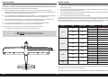
Center of Gravity ....................................................................................................................................................26
Control Throws ......................................................................................................................................................26
Advanced settings .................................................................................................................................................27
Mixing ...................................................................................................................................................................27
Prefl ight Checklist ..................................................................................................................................................27
Daily Flight Checks ................................................................................................................................................27
Limited Warranty ...................................................................................................................................................27
Warranty and Service Contact Information .............................................................................................................28
Instructions for Disposal of WEEE by Users in the European Union ..........................................................................28
Academy of Model Aeronautics National Model Aircraft Safety Code .......................................................................29

4EN
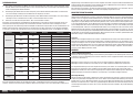
REQUIRED FOR COMPLETION, GAS ENGINE INSTALLATION
REQUIRED FOR COMPLETION, ALL POWER OPTIONS REQUIRED FOR COMPLETION, ELECTRIC MOTOR INSTALLATION
# Required Part # Description
1 DUB800 Tygon Gas Tubing,3-feet Large
1 GPMQ4777 Spinner 3-inch Nylon Aluminum Black
1 HAN116 Fuel Filler with “T” and Overfl ow Fitting
1 SPMAR12310T AR12310T 12CH PowerSafe Telemetry Receiver
1 SPMB4000LPRX 4000mAh 2S 7.4V LiPo Rx Battery
1 SPMSA6320 A6320 H-T/H-S Brushless HV Servo
1 SPMA3002 Heavy-Duty Servo Extension 9-inch
2 SPMA3006 Heavy-Duty Servo Extension 36-inch
8
SPMSA6380 A6380 H-T/H-S Digital HV Servo
# Required Part # Description
6 HAN9154 Aluminum Servo Arm, 1.5-inch SPM JR
2 SPMA3002 Heavy-Duty Servo Extension 9-inch
4 SPMA3004 Heavy-Duty Servo Extension 18-inch
2 SPMA3007 Heavy-Duty Servo Extension 48-inch
1 SPMSP3104 Aluminum Double Servo Arm, 3-inch
Gas Powered Version, All
Gas Powered Version, DLE-35RA
Gas Powered Version, DLE-55RA
Electric Powered Version, All
Electric Powered Version, Rimfi re 1.70
Electric Powered Version, Power 180
# Required Part # Description
1 DLEG0435 DLE-35RA Rear Exhaust Gas Engine with Electronic Ignition
1 MAS1810B Wood-Maple - 18 x 10 Propeller
# Required Part # Description
1 DLEG0455 DLE-55RA Gas Rear Exhaust Gas Engine with Electronic Ignition
1 22 x 8 or 23 x 8 Propeller
# Required Part # Description
1 CSE010013100 Talon HV120 ESC 010-0131-00
1 GPMQ4777 Spinner 3-inch Nylon Aluminum Black
1 SPMAR9350 AR9350 9 Channel AS3X Receiver
7 SPMSA6320 A6320 H-T/H-S Brushless HV Servo
1 SPMXCA506 IC5 Battery Series Harness 4-inch 10AWG
# Required Part # Description
1 APC20010E Electric Propeller, 20 x 10E
1 GPMG4796 Rimfi re 1.70 63-62-200 Outrunner
# Required Part # Description
1 APC20010E Electric Propeller, 20 x 10E
1 EFLM4180A Power 180 BL Outrunner Motor,195Kv

5 EN
Timber 110 30–50cc ARF
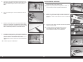
REMOVING WRINKLES
The covering of your model may develop wrinkles during shipping. Use a covering iron (HAN101) with a sealing iron
sock (HAN141) to remove them. Start with a lower heat setting and use caution while working around areas where the
colors overlap to prevent separating the colors. It is also advised to use caution around the clear windows and wing
tips as these items are plastic and could distort with excessive heat. Avoid using too much heat, which could also
separate the colors. Placing a cool damp cloth on adjacent colors will also help prevent the separation of the colors
while removing wrinkles. Only use a heat gun (HAN100) once the covering iron has been used.
BUILDING PRECAUTIONS
Prepare the work surface prior to beginning the build. The surface should be soft and free of any sharp objects. We
recommend resting the airframe parts on a soft towel or pit mat to prevent scratching or denting the surface of the
aircraft.
TRANSPORTATION AND STORAGE
When transporting and storing your model, you will need a minimum of 70 inches (1.8m) in length, and 28 inches
(54cm) in height to accommodate the size of the fuselage. We also recommend the use of wing and stabilizer bags to
help protect these surfaces during transport and storage. The control horns and linkages can cause damage to other
surfaces even when placed in storage bags. Always transport and store the wings and stabilizer so the linkages do not
contact other panels to prevent damage.
REPLACEMENT COVERING
Your model is covered with UltraCote® fi lm in the following colors. If repairs are required, order these coverings to
make those repairs.
HANU872 Bright Yellow
HANU873 Deep Blue
HANU866 True Red
HANU881 Silver
CHECKING BLIND NUTS
When building the aircraft, you will be required to thread machine screws into blind nuts. We recommend pre-threading
the screws to make sure the blind nuts are clear of any debris. If the screws do not thread in easily, clear the threads
using the appropriate tap and tap handle.
TOOLS REQUIRED
Description
Adjustable wrench
Balancing stand
Box wrench: 14mm and 17mm
Clamps
Crimping tool
Drill and tap set, metric
Drill bit set, Imperial or Metric
Epoxy brushes
Felt-tipped pen
Hemostats
Hex wrench set, Imperial and Metric
Hobby knife with #11 blade
Hobby scissors
Hook and loop straps
Hook and loop tape
Isopropyl alcohol
Light machine oil
Low-tack tape
Mixing sticks
Needle nose pliers
Nut driver set, Imperial and Metric
Paper towels
Pencil
Petroleum jelly
Phillips screwdriver: #1, #2
Pin vise
Rotary tool
Ruler
Sanding bar
Sanding drum for rotary tool
Sandpaper
Scissors
Side cutters
Square
Tap handle
Tapered reamer
Tie wraps
Toothpicks
Wire stripper

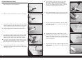
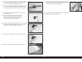
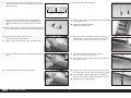
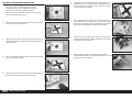
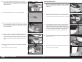
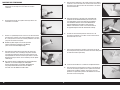
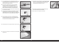
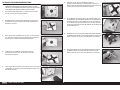
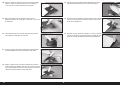
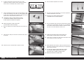
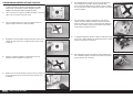
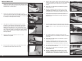
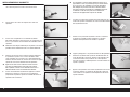
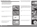
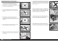
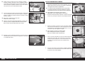
1. There are two different ball links included with the kit. The ball link
with the fl anged ball is used at the servo arm.
2. The ball link with the non-fl anged ball is used at the control horns.
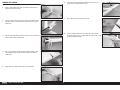
4. Use medium-grit sandpaper to lightly sand the aileron control horn
where it fi ts into the aileron. Clean the sanded area using a paper
towel and isopropyl alcohol to remove any debris or oils. This
provides the surface texture necessary for the epoxy to bond to.
Use low-tack tape on the painted area to help prevent removing
paint from the exposed portion of the control horn. Low-tack tape
will also prevent lifting the paint when the tape is removed.
5. Test fi t the control horn in the slot. Use a square to make sure the
control horn is perpendicular to the control surface. Do not force the
control horn in the slot.
3. Insert the M3 x 15 socket head cap screw into the hole in the aileron
control horn. Remove any paint using a hobby knife and #11 blade
so the screw fi ts into the hole easily. Check all the control horns.
The hole should be just large enough for the screw to slide
through, yet still fit snugly in the hole and not move excessively.
If the control horn fits tightly, or is not square, use a rotary
tool 3/32-inch (2.5mm) drill bit to carefully enlarge and
reshape the hole. Wrap a piece of low-tack tape around the
drill bit to set the depth of the drill bit so it won’t accidentally
pass through the opposite side of the control surface.
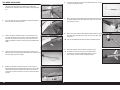
6. Slide the control horn plate up from the part that glues into the
control surface and not down from the painted control horn end.
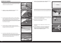
Read through steps 6 through 12 before mixing any epoxy.
8. Remove the control horn from the control surfaces. Mix 10ml of
30-minute epoxy. Apply epoxy to the slot in the aileron and fl ap.
Make sure the epoxy gets into the slot for a good bond between the
surfaces and control horn.
9. Apply epoxy to the area of the control horn that fi ts into the slots.
Use enough epoxy so the control horns will be fully bonded to the
control surfaces.
7. Check that the control horn plate fi ts fl ush against the control
surface when the control horn is in position. Check both control
horns at the same time.
CONTROL HORN INSTALLATION
6EN

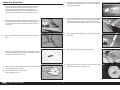
10. Make sure to apply epoxy on all surfaces of the control horn,
including the surface between the control horns.
11. Insert the control horns in the slots. Remove any excess epoxy using
a paper towel and isopropyl alcohol.
13. Follow the previous steps to install the control horns for the
elevators.
14. Place tape over the painted surface of the rudder control horn to
prevent removing any unwanted paint. Use medium-grit sandpaper
to lightly sand the control horn where it fi ts into the rudder. Clean the
sanded area using a paper towel and isopropyl alcohol to remove
any debris or oils. This provides the surface texture necessary for
the epoxy to bond to.
12. Fit the control horn ball link between the control horns. Slide the M3
x 15 socket head cap screws through the control horns and ball link
to hold the control horns in alignment until the epoxy fully cures.
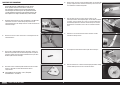
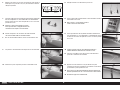
15. Use a hobby knife with a #11 blade or thin fi le to remove the paint
from the slots of the control horn plate.
16. Slide the control horn plate on the rudder control horn. It may be
necessary to lightly trim the opening in the plate to fi t over the
control horn.
18. Slide the remaining control horn in the rudder.
19. Check that the control horns can be aligned parallel in the rudder.
They must also be centered and square to the rudder center line.
17. Slide the rudder control horn in the slot in the rudder. It may require
trimming the slot in the rudder to fi t the control horn using the rotary
tool and drill bit.
7 EN
Timber 110 30–50cc ARF

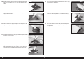
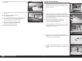
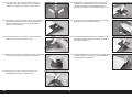
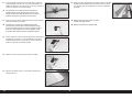
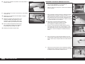
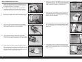
20. Remove the control horns. Place low-tack tape around the control
horn. The tape should be 1/32-inch (1mm) from the control horn as
shown.
21. Slide the control horn partially in the slot. Mix and apply 30-minute
epoxy to the control horn.
23. Center the control horn and use a paper towel and isopropyl alcohol
to remove any excess epoxy.
24. Repeat the process for the remaining rudder control horn. Fit two
ball ends between the horns, then use M3 x 15 socket head cap
screws to keep the control horns aligned while the epoxy cures.
22. Slide the control horn slightly through the rudder so epoxy can be
applied on the opposite side.
25. Use a paper towel and isopropyl alcohol to remove excess epoxy
from between the control horns.
26. Before the epoxy fully cures, remove the tape from around the
control horn. Allow the epoxy to fully cure before proceeding.
27. Use a small amount of 5-minute epoxy the control horn plates
in position. Remove any excess epoxy using a paper towel and
isopropyl alcohol.
8EN

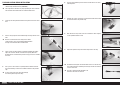
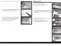
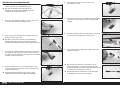
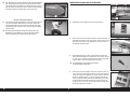
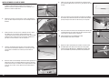
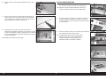
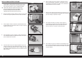
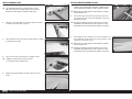
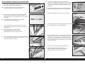
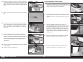
1. Secure an 18-inch (460mm) servo extension to the servo using a
commercially available retainer (SPMA3054).
The length of the extension may vary depending on servo selection.
The extension listed works with the recommended servos.
2. Tie or tape the string located inside the wing to the end of the servo
lead.
4. Fit the servo in the wing with the servo output toward the leading
edge. The servo arm will be centered in the opening. Mark the
locations for the servo mounting screws using a pencil, then remove
the servo.
5. Use a pin vise and a 5/64-inch (2mm) drill bit to drill the holes for
the servo mounting screws in the locations marked in the previous
step.
If using a drill, make sure not to drill through
the covering on the top of the wing.
3. Use the string to pull the servo lead through the wing and out at the
root.
We left a small amount of the string on the aileron
servo lead so it can be quickly differentiated between
the flap servo lead that will be installed later.
6. Thread a servo mounting screw into each of the holes in the servo
mounting holes.
7. Remove the screws, then apply a small amount of thin CA to harden
the threads made in the previous step.
9. Repeat the previous steps to install the fl ap servo in the wing
10. Assemble the linkage for the aileron. Make sure to use one of each
type of ball end when assembling the linkage. Thread each ball end
12 turns on the link.
The link is designed to be adjustable. The
threads on one end are reversed.
8. After the CA has fully cured, secure the servo to the cover using the
screws provided with the servo.
FLAP AND AILERON SERVO INSTALLATION
9 EN
Timber 110 30–50cc ARF

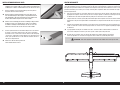
11. Secure the servo ball link to the servo arm using an M3 x 15 socket
head cap screw, M3 washer and M3 lock nut. Use a 2.5mm hex
wrench and 5.5mm nut driver to tighten the hardware.
The servo arm may not be threaded for metric hardware. It may
be necessary to drill and tap the hole for the M3 hardware, or drill
the hole over-size to pass the M3 screw through the servo arm.
12. Center the servo using the radio system. Attach the servo arm
parallel to the hinge line.
The servo may require the use of sub-trim to properly
align the servo arm parallel to the hinge line. Try to
get the servo arm as close to center as possible, using
the radio system only for minor adjustments.
14. Use the wrench included with the airplane to adjust the linkage.
15. Continue to adjust until the aileron is aligned with the wing tip.
13. Attach the servo linkage to the control horn using an M3 x 15 socket
head cap screw, M3 washer and M3 lock nut. Use a 2.5mm hex
wrench and 5.5mm nut driver to tighten the hardware.
16. Repeat the previous steps to install and adjust the fl ap linkage. This
installation will provide both up and down movement of the fl ap to
increase the aerobatic capabilities of this model.
Repeat this section to install the remaining aileron and flap servos.
Remember to turn the radio system off.
10EN

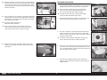
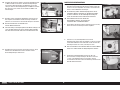
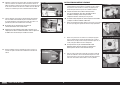
Do not mix any epoxy until instructed to do so.
1. Apply a small amount of oil to the center of the hinge to prevent
epoxy from entering the hinge.
2. Insert the hinge so the center of the hinge pin aligns with the front
edge of the bevel on the control surface. Check that the hinge can
move freely.
3. Slide the hinge into position. Position the hinge so it is perpendicular
to the hinge line when fully defl ected.
6. Use a paper towel and isopropyl alcohol to remove any excess
epoxy. Check the alignment of the hinge.
7. Apply epoxy to the hinge and holes in the fi n.
8. Slide the rudder into position. Use a paper towel and isopropyl
alcohol to remove any excess epoxy. Allow the epoxy to fully cure for
all hinges before proceeding.
4. Mix 1 ounce (30ml) of 30-minute epoxy. Remove the hinges, then
use a toothpick to apply epoxy inside each of the holes for the
rudder hinges.
5. Apply epoxy to the outside of the hinge using a toothpick
HINGING THE RUDDER
11 EN
Timber 110 30–50cc ARF

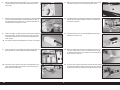
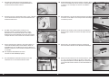
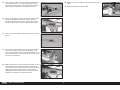
1. Place the steering arm on the bottom of the rudder with the leading
edge of the arm aligned with the rudder hinge line. Make the
locations for the mounting screws on the rudder using a felt-tipped
pen.
2. Use a drill and 1/16-inch (1.5mm) drill bit to drill the two locations
for the steering arm mounting screws.
4. Locate the tail wheel assembly and leaf springs. The springs are
different lengths. The longer spring will fi t against the assembly, and
the short spring against the fuselage.
5. Remove the three M3 x 30 socket head cap screws and place a
drop of threadlock on the threaded end of each screw. Fit the short
spring, long spring, and assembly on the fuselage. Use the three
screws and a 2.5mm hex wrench to secure the springs against the
fuselage.
3. Prepare the holes by threading an M2 x 15 sheet metal screw in
each hole. Remove the screw and place a few drops of thin CA in
each hole. Once the CA has fully cured, use the screws and a #2
Phillips screwdriver to attach the steering arm on the bottom of the
rudder.
6. Use pliers to bend the spring ends so the overall length is 4
1
/
2
inches
(114mm). Prepare both springs.
7. Attach the springs to the rudder steering arm. Wrap the loose end of
the spring around the main wire two or three times. Cut any excess
wire using side cutters.
8. Attach the springs to the tail wheel. Wrap the loose end of the spring
around the main wire two or three times. Cut any excess wire using
side cutters.
Use care not to damage the tiller arm when securing the springs.
9. Repeat the previous steps to install the remaining spring.
This model can also use the Super Scale Tailwheel from
the Hangar 9
®
XCub 60cc (HAN526014). Please be aware
this assembly is heavier than the supplied tail wheel.
TAIL WHEEL INSTALLATION
12EN

This model can also use the sprung undercarriage from the
Hangar 9
®
XCub 60cc (HAN526024). This optional undercarriage
is substantially heavier than the supplied landing gear, and can
detract from the aerobatic performance. The mounts for the
sprung gear (and optional floats) are factory installed. All it takes
is the covering to be removed when these options are chosen.
1. Remove the windscreen from the fuselage by releasing the magnets
at the top and rotating it forward and off the fuselage. Remove
the landing gear cover from the fuselage exposing the slot for the
landing gear.
3. Prepare the four M4 x 20 socket head cap screws by placing an M4
lock washer and M4 washer on each of the screws. Place a drop of
threadlock on the threads of each screw.
4. Locate the two inner landing gear plates. The screws will thread into
the two holes indicated in the photo.
Refer to checking the blind nuts on Page 5
before installing the screws.
2. Secure the axle to the landing gear using a 14mm and 17mm box
wrench.
5. Make sure the inner landing gear plates are oriented as shown in
the photo. For illustration purposes, they are shown here with the
landing gear not installed.
6. Attach the landing gear to the fuselage using the screws and plates
from the previous steps. A 2.5mm hex wrench through the landing
gear mounting hole and fuselage can help guide the plate into
position Leave the hardware loose until all four screws are installed.
8. Apply a drop of light machine oil on each of the axles.
7. Use a 3mm hex wrench to tighten the screws securing the gear to
the fuselage.
9. Slide the wheel on the axle. The wheel is secured using the retaining
clip through the hole near the end of the axle.
LANDING GEAR INSTALLATION
13 EN
Timber 110 30–50cc ARF

10. Use contact cement or two-sided tape to attach the landing gear
cover to the fuselage. Using tape allows the cover to be removed
for maintenance or to replace the landing gear or upgrade to the
optional fl oats or tundra gear in the future.
1. Remove the hatch from the side of the fuselage.
3. Install the rudder servo in the fuselage with the output toward the
front of the fuselage. Make sure to harden the mounting screw
locations with thin CA before installing the servo.
4. Thread the servo ball end on the cable fi tting. Thread the ball end
ten turns to make sure it is secure, and this allows for adjustment to
tighten the cables later. Prepare two servo ball ends.
Prepare the two ball ends and cable fitting for the control horns.
2. Remove the hatch from the top of the fuselage.
5. Center the rudder servo using the radio system. Fit a 3 inch (76mm)
rudder servo arm on the servo so it is perpendicular to the servo
center line. Rotate the arm 180-degrees to get the closest position if
required. Use the sub-trim function on the transmitter to make any
fi nal adjustments. Mark the servo arm so it can be returned to its
location, then remove it from the servo.
RUDDER SERVO INSTALLATION
Optional Landing Gear Fairing
11. An optional landing gear fairing has been included and is glued to
the landing gear using fl exible adhesive. Use a clamp to hold the
landing gear fairing in position. Allow the adhesive to fully cure
before continuing the build of the model.
The landing gear fairings are not recommended when
flying from rough surfaces as the gear will flex and
the fairings may release from the landing gear.
14EN

6. Enlarge the holes that are 5/8 inch (16mm) from the center of the
servo using a pin vise and 1/8-inch (3mm) drill bit. The ball ends will
attach to these holes.
7. Attach the ball ends to the rudder servo arm using two M3 x 15
socket head cap screws, two M3 washers and two M3 lock nuts.
Tighten the hardware using a 2.5mm hex wrench and 5.5mm nut
driver.
Using a longer rudder servo arm and attaching the ball ends further
from the center of the arm will increase the amount of rudder throw.
9. Pass the cable through the hole in the cable fi tting, then through the
sleeve.
10. Use crimping pliers to secure the sleeve to the cable.
Before retrieving the cables, make sure they are
taped securely at the rear of the fuselage.
8. From the cables inside the fuselage, slide a sleeve on the cable.
11. Attach both rudder cables to the fi ttings.
12. Attach the rudder servo arm to the rudder servo using the hardware
included with the servo.
Do not cross the rudder cables when
installing the rudder servo arm.
Install both sides of the cable at the same time. This
will result in equal tension on both cables.
14. Slide a sleeve on the cable, slide the cable through the fi tting, then
back through the sleeve.
15. Lightly tension the cables, then use crimping pliers to secure the
sleeve to the cables. Use side cutters to remove any excess cable.
The rudder cables may stretch slightly over time. Periodically
check the cables to make sure there is still light tension on them.
Remember to turn the radio system off.
13. Attach the ball ends to the rudder control horns using an M3 x 15
socket head cap screw, M3 washer and M3 lock nut. Tighten the
hardware using a 2.5mm hex wrench and 5.5mm nut driver.
15 EN
Timber 110 30–50cc ARF
5/8 inch
(16mm)
5/8 inch
(16mm)

1. Use the hardware included with the servo to secure the elevator
servo in the stabilizer. Make sure the servo output faces the leading
edge of the stabilizer.
The elevator servo may be a snug fit and require
some maneuvering to fit it into position.
2. Assemble the linkage for the elevator. Make sure to use both types
of ball ends when assembling the linkage. Thread each ball end 12
turns on the link.
The link is designed to be adjustable. The
threads on one end are reversed.
3. Attach the servo ball end to the servo arm. Center the elevator servo
using the radio system and place the servo arm on the servo.
The servo may require the use of sub-trim to properly align
the servo arm perpendicular to the servo center line.
4. With the radio system off, rotate the elevator servo so the screws
can be installed to secure the arm if using the recommended Hangar
9 servo arms.
ELEVATOR AND ELEVATOR SERVO INSTALLATION
5. Slide the two 48-inch (1200mm) servo extensions through the
clear tube in the fuselage for the elevator servos. Make sure the
extensions are installed in the correct direction so they can be
connected to the receiver and elevator servos.
The length of the extension may vary depending on servo selection.
The extension listed works with the recommended servos.
6. Retrieve the ends of the leads at the rear of the fuselage.
8. With the radio system on and the elevator servo connected to the
receiver, attach the ball end to the control horn using an M3 x 15
socket head cap screw, M3 washer and M3 lock nut. Tighten the
hardware using a 5.5mm nut driver and 2.5mm hex wrench. Adjust
the linkage to center the elevator using the wrench provided.
9. Slide the stabilizer tube into the stabilizer tube socket.
The tube may be a tight fit in the socket. Polishing the tube with fine
sand paper or steel wool will help ease the installation of the tube.
7. Secure the lead in the fuselage to the elevator servo using a
commercially available retainer (SPMA3054).
16EN

10. Slide the stabilizer into position on the fuselage. Guide the leads into
the fuselage.
11. Secure the stabilizer to the fuselage using two M3 x 10 socket head
cap screw.
Refer to checking the blind nuts on Page 5
before installing the screws.
Place a drop of canopy glue on the screws before installation.
This will keep the screws from vibrating loose yet leave
them easily removable to disassemble the model.
Thumb screws have also been provided to attach
the stabilizer, making it easier to assemble and
disassemble your model without tools.
Remember to turn the radio system off.
An optional Aerotow Release (HAN526013) can be installed in
this model. It will also require the use of a high-torque servo.
1. Mount the servo in the fuselage with the servo output facing the
bottom of the fuselage.
2. Remove the covering from the fuselage for the aerotow release
using a hobby knife and #11 blade. Mount the aerotow release in the
top of the fuselage. Make sure the slot in the release is parallel to
the trailing edge of the wing. Use a drop of threadlock on the nut to
prevent it from vibrating loose.
There are two areas on the top of the fuselage that
are covered. The forward location is for lighting, and
the rear location for the aerotow release.
4. Thread a clevis on a 12-inch (300mm) pushrod (not included).
Remove any arms on the servo arm that will not be used using side
cutters. Attach the clevis to the servo arm.
5. Slide the pushrod through the aerotow release. Place the servo arm
back on the servo. Use the radio to move the servo to the locked
position.
3. Center the aerotow release servo and place the servo arm on the
servo perpendicular to the servo center line. Mark the arm that is
directly below the aerotow release.
OPTIONAL TOW HOOK RELEASE
17 EN
Timber 110 30–50cc ARF

6. Mark the pushrod at the edge of the release using a felt-tipped pen.
7. Remove the servo arm and pushrod from the fuselage. Cut the
pushrod at the mark. Use a fl at fi le to make a slight point on the end
of the pushrod so it will self-guide through the release.
8. Reinstall the servo arm and pushrod. Check the operation of the
release. Adjust the radio system if the servo binds at full release.
When in the release position, the end of the pushrod must be
completely clear of the slot in the body of the release.
Remember to turn the radio system off.
1. Install the receiver in the fuselage. Mount any remote receivers in
the fuselage using hook and loop tape.
Apply a small amount of 5-minute epoxy to the hook
and loop tape to secure it to the radio tray.
2. Connect the leads for the elevators and rudder, as well as the 18-
inch (460mm) extensions for the ailerons and fl aps to the receiver.
Route the leads for the ailerons and fl aps to the opening at the top of
the fuselage.
3. Follow the instructions included with the receiver for the correct
locations for the remote receivers.
The locations shown are possible locations. Ensure
the locations of the remote receivers will not interfere
with components installed later in the build.
RECEIVER INSTALLATION
18EN

Check the mount of any non-recommended motors
and verify that they can not be attached using the pre-
installed blind nuts. If not, the following outlines how to
modify the firewall for optional motor installations.
1. Mark the fi rewall of the motor box 12mm from the sides and up
5mm from the bottom using a pencil.
2. Place the motor mount on the fi rewall. Align the holes in the mount
on the lines made in the previous step.
4. Use a pencil to make the locations for the mounting screws through
the mount and on to the fi rewall.
5. Set the mount aside and use a drill and 5/32-inch (4mm) drill bit to
drill the holes in the fi rewall for the mounting screws.
3. Look through the back of the motor box to make sure the mount is
centered on the fi rewall. The mount will show equally though the
hole in the fi rewall.
OPTIONAL ELECTRIC MOTOR PREPARATION
6. Temporarily attach the mount to the fi rewall using four M4 x 20
socket head cap screws, four M4 washers and four M4 lock nuts to
attach the mount to the fi rewall. Use a 3mm hex wrench and 7mm
nut driver to tighten the hardware.
7. When attaching the mount, the washers and lock nut will clear the
pre-installed blind nuts as shown. If not, use a hobby knife and #11
blade to trim the wood around the nuts and washers so the washers
rest fl ush on the wood. Remove the mount from the fi rewall.
9. Attach the propeller adapter to the motor using the hardware
included with the adapter. Use a drop of threadlock on each screw to
prevent them from vibrating loose.
8. The mount can now be attached to the motor using the hardware
included with the motor. Use a drop of threadlock on each screw to
prevent them from vibrating loose.
19 EN
Timber 110 30–50cc ARF

1. Place the mounting template on the fi rewall. Use low-tack tape to
hold the template in position. Use a drill and 3/32-inch (2.5mm) drill
bit to drill the four holes in the fi rewall to attach the motor box.
When using power systems other than the recommended
choices, we advise using the mounting template as a test
to ensure hole alignment before drilling the firewall.
2. Remove the template from the fuselage. Use a drill and 5/32-inch
(4mm) drill bit to enlarge the holes from the previous step.
4. Attach the propeller adapter to the motor using the hardware
included with the adapter. Use a drop of threadlock on each screw to
prevent them from vibrating loose.
5. Attach your motor to the fi rewall. Adjust the position of the fi rewall
so the distance from the rear of the motor box to the face of the
drive washer measures 7
1
/
8
inches (181mm). Use a pencil to mark
the location of the fi rewall on the sides and bottom of the motor box.
3. Attach the mount to the motor using the hardware included with the
motor. Use a drop of threadlock on each screw to prevent them from
vibrating loose.
ELECTRIC MOTOR INSTALLATION
6. Remove the motor from the fi rewall. Mix 4 ounces (120ml) of
30-minute epoxy. Slide the fi rewall sand apply epoxy to the sides
and bottom of the motor box. Slide the fi rewall back in position.
7. Use low-tack tape to hold the fi rewall in position until the epoxy
fully cures. Make sure the fi rewall does not move during the curing
process.
9. Attach the motor to the fi rewall using four M4 x 20 socket head cap
screws, four M4 washers and four M4 lock nuts. Use a 3mm hex
wrench and 7mm nut driver to tighten the hardware.
8. Attach the motor box to the fuselage using four M4 x 20 socket head
cap screws, four M4 washers and four M4 lock nuts. Use a 3mm hex
wrench and 7mm nut driver to tighten the hardware.
20EN
La pagina sta caricando ...
La pagina sta caricando ...
La pagina sta caricando ...
La pagina sta caricando ...
La pagina sta caricando ...
La pagina sta caricando ...
La pagina sta caricando ...
La pagina sta caricando ...
La pagina sta caricando ...
La pagina sta caricando ...
La pagina sta caricando ...
La pagina sta caricando ...
La pagina sta caricando ...
La pagina sta caricando ...
La pagina sta caricando ...
La pagina sta caricando ...
La pagina sta caricando ...
La pagina sta caricando ...
La pagina sta caricando ...
La pagina sta caricando ...
La pagina sta caricando ...
La pagina sta caricando ...
La pagina sta caricando ...
La pagina sta caricando ...
La pagina sta caricando ...
La pagina sta caricando ...
La pagina sta caricando ...
La pagina sta caricando ...
La pagina sta caricando ...
La pagina sta caricando ...
La pagina sta caricando ...
La pagina sta caricando ...
La pagina sta caricando ...
La pagina sta caricando ...
La pagina sta caricando ...
La pagina sta caricando ...
La pagina sta caricando ...
La pagina sta caricando ...
La pagina sta caricando ...
La pagina sta caricando ...
La pagina sta caricando ...
La pagina sta caricando ...
La pagina sta caricando ...
La pagina sta caricando ...
La pagina sta caricando ...
La pagina sta caricando ...
La pagina sta caricando ...
La pagina sta caricando ...
La pagina sta caricando ...
La pagina sta caricando ...
La pagina sta caricando ...
La pagina sta caricando ...
La pagina sta caricando ...
La pagina sta caricando ...
La pagina sta caricando ...
La pagina sta caricando ...
La pagina sta caricando ...
La pagina sta caricando ...
La pagina sta caricando ...
La pagina sta caricando ...
La pagina sta caricando ...
La pagina sta caricando ...
La pagina sta caricando ...
La pagina sta caricando ...
La pagina sta caricando ...
La pagina sta caricando ...
La pagina sta caricando ...
La pagina sta caricando ...
La pagina sta caricando ...
La pagina sta caricando ...
La pagina sta caricando ...
La pagina sta caricando ...
La pagina sta caricando ...
La pagina sta caricando ...
La pagina sta caricando ...
La pagina sta caricando ...
La pagina sta caricando ...
La pagina sta caricando ...
La pagina sta caricando ...
La pagina sta caricando ...
La pagina sta caricando ...
La pagina sta caricando ...
La pagina sta caricando ...
La pagina sta caricando ...
La pagina sta caricando ...
La pagina sta caricando ...
La pagina sta caricando ...
La pagina sta caricando ...
La pagina sta caricando ...
La pagina sta caricando ...
La pagina sta caricando ...
La pagina sta caricando ...
La pagina sta caricando ...
La pagina sta caricando ...
La pagina sta caricando ...
La pagina sta caricando ...
-
 1
1
-
 2
2
-
 3
3
-
 4
4
-
 5
5
-
 6
6
-
 7
7
-
 8
8
-
 9
9
-
 10
10
-
 11
11
-
 12
12
-
 13
13
-
 14
14
-
 15
15
-
 16
16
-
 17
17
-
 18
18
-
 19
19
-
 20
20
-
 21
21
-
 22
22
-
 23
23
-
 24
24
-
 25
25
-
 26
26
-
 27
27
-
 28
28
-
 29
29
-
 30
30
-
 31
31
-
 32
32
-
 33
33
-
 34
34
-
 35
35
-
 36
36
-
 37
37
-
 38
38
-
 39
39
-
 40
40
-
 41
41
-
 42
42
-
 43
43
-
 44
44
-
 45
45
-
 46
46
-
 47
47
-
 48
48
-
 49
49
-
 50
50
-
 51
51
-
 52
52
-
 53
53
-
 54
54
-
 55
55
-
 56
56
-
 57
57
-
 58
58
-
 59
59
-
 60
60
-
 61
61
-
 62
62
-
 63
63
-
 64
64
-
 65
65
-
 66
66
-
 67
67
-
 68
68
-
 69
69
-
 70
70
-
 71
71
-
 72
72
-
 73
73
-
 74
74
-
 75
75
-
 76
76
-
 77
77
-
 78
78
-
 79
79
-
 80
80
-
 81
81
-
 82
82
-
 83
83
-
 84
84
-
 85
85
-
 86
86
-
 87
87
-
 88
88
-
 89
89
-
 90
90
-
 91
91
-
 92
92
-
 93
93
-
 94
94
-
 95
95
-
 96
96
-
 97
97
-
 98
98
-
 99
99
-
 100
100
-
 101
101
-
 102
102
-
 103
103
-
 104
104
-
 105
105
-
 106
106
-
 107
107
-
 108
108
-
 109
109
-
 110
110
-
 111
111
-
 112
112
-
 113
113
-
 114
114
-
 115
115
-
 116
116


Hangar 9 HAN2530 Manuale del proprietario
- Categoria
- Giocattoli telecomandati
- Tipo
- Manuale del proprietario
in altre lingue
- English: Hangar 9 HAN2530 Owner's manual
- français: Hangar 9 HAN2530 Le manuel du propriétaire
- Deutsch: Hangar 9 HAN2530 Bedienungsanleitung
Documenti correlati
-
 Hangar 9 HAN5260 Manuale del proprietario
-
 Hangar 9 HAN4720CR Manuale del proprietario
-
 Hangar 9 HAN2890 Manuale del proprietario
-
 Hangar 9 HAN2390 Manuale del proprietario
-
 Hangar 9 HAN3390 Manuale utente
-
Evolution 33cc Manuale del proprietario
-
 Hangar 9 HAN2370 Manuale del proprietario
-
 Hangar 9 HAN5065 Manuale del proprietario
-
 Hangar 9 HAN5280 Manuale del proprietario
-
 Hangar 9 HAN5260B Manuale del proprietario


