
AU DIO
VIDEO
PWR
A / V
RF
CH
#
AU DIO
VIDEO
PWR
A / V
RF
CH
#
AU DIO
VIDEO
PWR
A / V
RF
CH
#
AU DIO
VIDEO
PWR
A / V
RF
CH
#
AU DIO
VIDEO
PWR
A / V
RF
CH
#
AU DIO
VIDEO
PWR
A / V
RF
CH
#
AU DIO
VIDEO
PWR
A / V
RF
CH
#
AU DIO
VIDEO
PWR
A / V
RF
CH
#
AU DIO
VIDEO
PWR
A / V
RF
CH
#
AU DIO
VIDEO
PWR
A / V
RF
CH
#
AU DIO
VIDEO
PWR
A / V
RF
CH
#
AU DIO
VIDEO
PWR
A / V
RF
CH
#
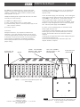
P OW E R S U P P LY
®
RMM12 Rac
k Mount 1
The RMM12 Ra ck Mount supports a single Drake Power
Supply and up to (12) modular Audio/Video modulators to
congure a professional quality, modular, headend system,
which optimizes rack spac e.
Identify the following items shipped with this kit of rack mount
assem bly and ca ble assem bly:
(1) RMM12 Ra ck Mount chassi s.
(1) Wire, ground bonding chassis to power supply
(1) C able Ass embly, 37-pin D connector (mal e) to (12) fan-out
3-Ckt connectors (female)
(2) End Cap s, Bla ck
Ins tallation :
Adequate ventilation is very important in multichan nel
installations. Ra ck units should be spaced apa rt by at least
one panel height wherever possible, and some air movement
is advisable in enclos ed rack cabi
nets. E xces s ive heat will
shorten the life of components and individual module(s).
Power supply performance will also be degraded without
proper cooling.
If desired, the supplied black end caps can be installed over
the mounting ears of the RMM12 and secured by the rack
support screws.
Locate the Power Supply (sold sepa rately) . P rior to sliding the
power supply into the right-ha nd side top and bottom slide rails
of the RMM12, loosen the #6-32 scr ew located on the top
surface of the power supply. Position the free end of the
ground wire lug (other end of wire fastened to RMM12) under
the #6-32 scr ew, and tighten the scr ew to secure the ground
wire. Slide the power supply into the RMM12.
If necessa ry, use the following steps to remove the Drake
Power Supply from the rack:
1) Rem ove
the module immediately adjacent to the Drake
Power Suppl y. Be aware that the module power ca ble will
become disconnected from the rear when the module is
removed.
2) Now grasp the edge of the Drake Power Supply front panel
and remove the unit from rack.
3) R econnect the module power cable then replace the
adjacent module as required.
RM M12
BL ACK END CAP
(DEC OR ATI VE )
SECURE LUG (G R OUND
BONDING WIRE) UNDER
#6- 32 S C R E W HEA D.
SLIDE RAIL (INTERNAL
TO R ACK CHASSI S , TOP
AND B OT TOM).
BL ACK END CAP
(DEC OR ATIVE)
FIGURE 1 - Front Vi ew of Rack Mount System with
Power Supply
® is a registered trademark of the R . L. Drake Holdings LLC
© Copyri ght 2013 R .L. Drake Holdings LLC
P/N: 651231900A
Printed in Taiwan.
R .L. DR A K E HOLDINGS LLC
9900 Springboro Pike
Miamisburg, Ohio 45342
CUSTOMER SERVICE AND PARTS TELEPHONE: +1 (937) 746-6990
FAX: +1 (937) 806-1510
http://www.rldrake.com
®

100-240 V
50/60 Hz
75 WATTS
~
VIDEO INPUT VIDEO INPUT VIDEO INPUT VIDEO INPUT VIDEO INPUT VIDEO INPUT VIDEO INPUT VIDEO INPUT VIDEO INPUT VIDEO INPUT VIDEO INPUT VIDEO INPUT
AUDIO INPUT AUDIO INPUT AUDIO INPUT AUDIO INPUT AUDIO INPUT AUDIO INPUT AUDIO INPUT AUDIO INPUT AUDIO INPUT AUDIO INPUT AUDIO INPUT AUDIO INPUT
DC INPUT DC INPUT DC INPUT DC INPUT DC INPUT DC INPUT DC INPUT DC INPUT DC INPUT DC INPUT DC INPUT DC INPUT
RF OUT RF OUT RF OUT RF OUT RF OUT RF OUT RF OUT RF OUT RF OUT RF OUT RF OUT RF OUT
+5V
+12V
GND
+5V
+12V
GND
+5V
+12V
GND
+5V
+12V
GND
+5V
+12V
GND
+5V
+12V
GND
+5V
+12V
GND
+5V
+12V
GND
+5V
+12V
GND
+5V
+12V
GND
+5V
+12V
GND
+5V
+12V
GND
+12 VDC
(3A Max):
Pins 2, 3, 5,
6, 8, 9,11,
13, 14, 16,
17, 19.
+5 VDC
(3A Max):
Pins 1, 4, 7,
12, 15, 18,
21, 24, 27,
30, 33, 36.
GND:
Pins 10, 20,
22, 23, 25,
26, 28, 29,
31, 32, 34,
35, 37.
37
19
20
1
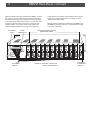
2 RMM12 Rack Mount, continued
With the Drake Power Supply installed in the RMM12, connect
the 37-pin D connector to the mating connector at the rear of
the Drake Power Supply. Slide individual modules (maximum
of 12 units) into the desired rack locations. Connect one 3-Ckt
connector to the rear panel power input connector of each
installed module. Connect the shorter 3-Ckt cables to the
modules that are located closer to the power supply, and
AC POWER
CORD
3-PIN MALE
CONNECTOR
(TYPICAL)
AUDIO/VIDEO MODULATORS
(REAR PANEL VIEW)
DC POWER
CABLES
FIGURE 2 - Rear View of System with
12 Audio/Video Modulators.
37-PIN
CONNECTOR
longer cables to the modules located farther from the power
supply. Avoid stretching the cables or routing them where
damage to the cable is likely.
After the desired modules are installed into the RMM12 and
the RMM12 is secured in the rack, connect the power supply
to a source of AC power.
-
 1
1
-
 2
2


in altre lingue
- English: DRAKE RMM12
Altri documenti
-
Juniper QFX5220 Manuale utente
-
-
 Sapphire Audio PI-AM3RS760G2 Quick Installation Manual
-
Tyan Transport TN27 B4987 Manuale utente
-
-
-
Nvidia nForce 680I LT SLI Manuale utente
-
Tyan Thunder S4987 Manuale utente
-
Atlona AT-HDR-M2C-QUAD Guida d'installazione
-
Juniper QFX5120-48Y-AFI2 Manuale utente
