
EBE-4U / EBE-4UG
ASUS IPC
(Industrial Computer Barebone)
User’s Manual
EBE-4U
EBE-4UG
Applicable for products with P/N of 90AE0060* & 90AE00H*

ii
E22593
Revised Edition v2
September 2023
Copyright © 2023 ASUSTeK Computer Inc. All Rights Reserved.
No part of this manual, including the products and software described in it, may be reproduced,
transmitted, transcribed, stored in a retrieval system, or translated into any language in any form or by any
means, except documentation kept by the purchaser for backup purposes, without the express written
permission of ASUSTeK Computer Inc. (“ASUS”).
Product warranty or service will not be extended if: (1) the product is repaired, modied or altered, unless
such repair, modication of alteration is authorized in writing by ASUS; or (2) the serial number of the
product is defaced or missing.
ASUS PROVIDES THIS MANUAL “AS IS” WITHOUT WARRANTY OF ANY KIND, EITHER EXPRESS
OR IMPLIED, INCLUDING BUT NOT LIMITED TO THE IMPLIED WARRANTIES OR CONDITIONS OF
MERCHANTABILITY OR FITNESS FOR A PARTICULAR PURPOSE. IN NO EVENT SHALL ASUS, ITS
DIRECTORS, OFFICERS, EMPLOYEES OR AGENTS BE LIABLE FOR ANY INDIRECT, SPECIAL,
INCIDENTAL, OR CONSEQUENTIAL DAMAGES (INCLUDING DAMAGES FOR LOSS OF PROFITS,
LOSS OF BUSINESS, LOSS OF USE OR DATA, INTERRUPTION OF BUSINESS AND THE LIKE),
EVEN IF ASUS HAS BEEN ADVISED OF THE POSSIBILITY OF SUCH DAMAGES ARISING FROM ANY
DEFECT OR ERROR IN THIS MANUAL OR PRODUCT.
SPECIFICATIONS AND INFORMATION CONTAINED IN THIS MANUAL ARE FURNISHED FOR
INFORMATIONAL USE ONLY, AND ARE SUBJECT TO CHANGE AT ANY TIME WITHOUT NOTICE,
AND SHOULD NOT BE CONSTRUED AS A COMMITMENT BY ASUS. ASUS ASSUMES NO
RESPONSIBILITY OR LIABILITY FOR ANY ERRORS OR INACCURACIES THAT MAY APPEAR IN THIS
MANUAL, INCLUDING THE PRODUCTS AND SOFTWARE DESCRIBED IN IT.
Products and corporate names appearing in this manual may or may not be registered trademarks or
copyrights of their respective companies, and are used only for identication or explanation and to the
owners’ benet, without intent to infringe.

iii
Table of contents
Notices ............................................................................................................v
Safety information .......................................................................................... vi
About this guide ............................................................................................ vii
System package contents ............................................................................ viii
Chapter 1 System introduction
1.1 Welcome! ......................................................................................... 1-2
1.2 Brief introduction .............................................................................. 1-2
1.3 Front panel ...................................................................................... 1-4
1.4 Rear panel ........................................................................................ 1-5
1.5 Internal components ......................................................................... 1-8
Chapter 2 Motherboard information
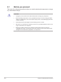
2.1 Before you proceed .......................................................................... 2-2
2.2 Motherboard layout .......................................................................... 2-3
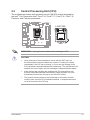
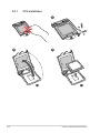
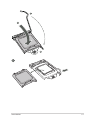
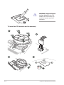
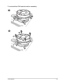
2.3 Central Processing Unit (CPU)......................................................... 2-5
2.3.1 CPU installation ................................................................... 2-6
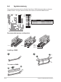
2.4 System memory ............................................................................. 2-10
2.5 Jumpers.......................................................................................... 2-11
2.6 Connectors ..................................................................................... 2-14
Chapter 3 BIOS setup
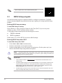
3.1 BIOS Setup program ........................................................................ 3-2
3.2 Main menu........................................................................................ 3-3
3.2.1 System Date [Day MM/DD/YYYY] ....................................... 3-3
3.2.2 System Time [HH:MM:SS] .................................................. 3-3
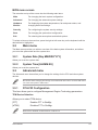
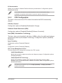
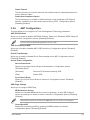
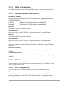
3.3 Advanced menu ............................................................................... 3-3
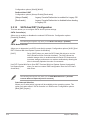
3.3.1 PCH-FW Conguration ........................................................ 3-3
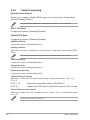
3.3.2 Trusted Computing .............................................................. 3-4
3.3.3 CPU Conguration .............................................................. 3-5
3.3.4 Graphics Conguration ........................................................ 3-6
3.3.5 PCI Express Conguration .................................................. 3-6
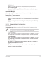
3.3.6 AMT Conguration .............................................................. 3-9
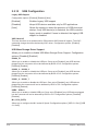
3.3.7 CSM Conguration ............................................................ 3-10
3.3.8 Super IO Conguration ...................................................... 3-10
3.3.9 Serial Console Redirection ................................................ 3-12
3.3.10 SATA And RST Conguration ........................................... 3-14

iv
Table of contents
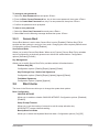
3.3.11 Network Stack Conguration ............................................. 3-15
3.3.12 USB Conguration ............................................................. 3-16
3.3.13 NVMe Conguration .......................................................... 3-17
3.3.14 Onboard Devices Conguration ........................................ 3-17
3.3.15 EZ-Flash ............................................................................ 3-17
3.3.16 APM Conguration ............................................................ 3-17
3.3.17 Watchdog Timer ................................................................ 3-19
3.3.19 Miscellaneous .................................................................... 3-19
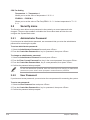
3.4 Hardware Monitor menu ................................................................. 3-19
3.4.1 Smart Fan Mode ................................................................ 3-19
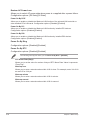
3.5 Security menu ................................................................................ 3-20
3.5.1 Administrator Password .................................................... 3-20
3.5.2 User Password .................................................................. 3-20
3.5.3 Secure Boot ....................................................................... 3-21
3.6 Boot menu ...................................................................................... 3-21
3.7 Exit menu ....................................................................................... 3-22
Appendix
Notices ........................................................................................................ A-1
Service and Support ...................................................................................A-5

v
Notices
Canadian Department of Communications Statement
This digital apparatus does not exceed the Class B limits for radio noise emissions from
digital apparatus set out in the Radio Interference Regulations of the Canadian Department
of Communications.
This class B digital apparatus complies with Canadian ICES-003.
WARNING! The use of shielded cables for connection of the monitor to the graphics card
is required to assure compliance with FCC regulations. Changes or modications to this
unit not expressly approved by the party responsible for compliance could void the user’s
authority to operate this equipment.
ASUS Recycling/Takeback Services
ASUS recycling and takeback programs come from our commitment to the highest standards
for protecting our environment. We believe in providing solutions for you to be able to
responsibly recycle our products, batteries, other components, as well as the packaging
materials. Please go to http://csr.asus.com/english/Takeback.htm for the detailed recycling
information in different regions.
REACH
Complying with the REACH (Registration, Evaluation, Authorisation, and Restriction of
Chemicals) regulatory framework, we published the chemical substances in our products at
ASUS REACH website at http://csr.asus.com/english/REACH.htm
Federal Communications Commission Statement
This device complies with Part 15 of the FCC Rules. Operation is subject to the following two
conditions:
•
This device may not cause harmful interference, and
•
This device must accept any interference received including interference that may
cause undesired operation.
This equipment has been tested and found to comply with the limits for a Class B digital
device, pursuant to Part 15 of the FCC Rules. These limits are designed to provide
reasonable protection against harmful interference in a residential installation. This
equipment generates, uses and can radiate radio frequency energy and, if not installed
and used in accordance with manufacturer’s instructions, may cause harmful interference
to radio communications. However, there is no guarantee that interference will not occur
in a particular installation. If this equipment does cause harmful interference to radio or
television reception, which can be determined by turning the equipment off and on, the user
is encouraged to try to correct the interference by one or more of the following measures:
•
Reorient or relocate the receiving antenna.
•
Increase the separation between the equipment and receiver.
•
Connect the equipment to an outlet on a circuit different from that to which the receiver
is connected.
•
Consult the dealer or an experienced radio/TV technician for help.

vi
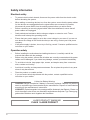
Safety information
Electrical safety
• To prevent electric shock hazard, disconnect the power cable from the electric outlet
before relocating the system.
• When adding or removing devices to or from the system, ensure that the power cables
for the devices are unplugged before the signal cables are connected. If possible,
disconnect all power cables from the existing system before you add a device.
• Before connecting or removing signal cables from the motherboard, ensure that all
power cables are unplugged.
• Seek professional assistance before using an adapter or extension cord. These
devices could interrupt the grounding circuit.
• Ensure that your power supply is set to the correct voltage in your area. If you are not
sure about the voltage of the electrical outlet you are using, contact your local power
company.
• If the power supply is broken, do not try to x it by yourself. Contact a qualied service
technician or your retailer.
Operation safety
•
Before installing the motherboard and adding devices on it, carefully read all the
manuals that came with the package.
•
Before using the product, ensure that all cables are correctly connected and the power
cables are not damaged. If you detect any damage, contact your dealer immediately.
•
To avoid short circuits, keep paper clips, screws, and staples away from connectors,
slots, sockets and circuitry.
•
Avoid dust, humidity, and temperature extremes. Do not place the product in any area
where it may become wet.
•
Place the product on a stable surface.
•
If you encounter technical problems with the product, contact a qualied service
technician or your retailer.
Lithium-Ion Battery Warning
CAUTION: Danger of explosion if battery is incorrectly replaced. Replace only with the
same or equivalent type recommended by the manufacturer. Dispose of used batteries
according to the manufacturer’s instructions.
VORSICHT: Explosionsgetahr bei unsachgemäßen Austausch der Batterie. Ersatz nur
durch denselben oder einem vom Hersteller empfohlenem ähnljchen Typ. Entsorgung
gebrauchter Batterien nach Angaben des Herstellers.
LASER PRODUCT WARNING
CLASS 1 LASER PRODUCT

vii
Conventions used in this guide
WARNING: Indicates information that could prevent injury when completing a
task.
CAUTION: Indicates information to prevent damage to the components when
completing a task.
IMPORTANT: Instructions that you MUST follow to complete a task.
NOTE: Tips and additional information when completing a task.
Where to find more information
Refer to the following sources for additional information and for product and software
updates.
1. ASUS Website
The ASUS website worldwide provides updated information on ASUS hardware and
software products. Refer to the ASUS contact information.
2. Optional Documentation
Your product package may include optional documentation, such as warranty yers,
that may have been added by your dealer. These documents are not part of the
standard package.
About this guide
Audience
This guide provides general information and installation instructions about ASUS EBE-
4U barebone system. This guide is intended for users and administrators with experience
handling hardware and PC components.
How this guide is organized
This guide contains the following parts:
1. Chapter 1: System introduction
This chapter gives a general description of ASUS EBE-4U. The chapter lists system
features, physical descriptions of the front and rear panels, and an overview of internal
components.
2. Chapter 2: Motherboard info
This chapter provides details about the motherboard that comes with the system. This
chapter includes the motherboard layout, jumper settings, and connector locations.
3. Chapter 3: BIOS setup
This chapter provides a detailed guide to navigating and setting up the BIOS.

viii
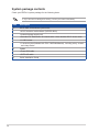
System package contents
Check your EBE-4U system package for the following items.
If any of the items is damaged or missing, contact your retailer immediately.
Item Description
1. ASUS EBE-4U barebone system with
• ASUS industrial motherboard (Q470EA-IM-A)
• Industrial power supply unit
• Standard 19” Rackmount 4U chassis with 1.2mm durable SGCC sheet metal
• 1 x M.2 screw
• 1 accessory box (labeled with P/N: 13AE0060Mxxxxx), including a key, screws
and clamp hooks
2. Cables
• Power SW cable
• SATA 6G cable
3. Quick Installation Guide

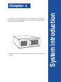
System introduction
This chapter gives a general description of ASUS EBE-4U. The chapter lists
system features, physical descriptions of the front and rear panels, and an
overview of internal components.
Chapter 1
The illustrations in this user manual are for reference only. Actual product
may vary.

1-2 Chapter 1: System introduction
1.1 Welcome!
Thank you for choosing the ASUS EBE-4U!
The ASUS EBE-4U provides cutting-edge performance and uncompromised reliability for
industrial use.
The system is powered by the ASUS motherboard that supports the 10th Intel® Core™ i9 / i7 /
i5 / i3, Pentium® and Celeron® processors in the Intel® socket 1200.
The system supports up to 128 GB of system memory using DDR4 2933/2666/2400 MHz
DIMMs. High-resolution graphics via integrated graphics controller or PCI Express x16 slots,
SATA 6.0Gb/s, USB 3.2 Gen 1 ports, USB 2.0 ports, and 8-channel audio features take you
ahead in the world of power computing.
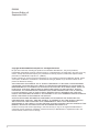
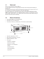
1.2 Brief introduction
• Color: Black (EBE-4U) or Gray (EBE-4UG)
• Net weight: refer to the data sheet
• Form factor: 450mm (H) x 482mm (D) x 172±2.0mm (H) (with handles)
• Operation temperature: 0~50°C
• Non-operation temperature: -40~85°C
• Relative humidity: 0% - 85%
• OS support:
Windows® 7 (32/64bit)
Windows® 10 (64bit)
Windows® 10 IoT Enterprise
Ubuntu
RedHat Enterprise
Fedora Workstation
OpenSUSE
L
D
H172±2.0mm
482mm
450mm

1-3
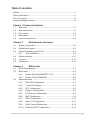
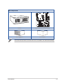
ASUS EBE-4U
Main components
PCIEX4_1
PCIEX4_2
PCIEX4_3
PCI_2
PCI_1
SPEAKER
SATA6G_4
128Mb
BIOS
SATA6G_3 SATA6G_2 SATA6G_1
CHASSIS
AT_ATX_SEL
SPDIF_OUT
WDT_EN
CLRTC
F_PANEL
USB1011
I2C
BUZZER
M.2(WIFI)
LPT
AAFP
TPM
EATXPWR
CPU_FAN CHA_FAN2
CHA_FAN3
CHA_FAN1
BATTERY
PCIEX16_1
PCIEX16_2
Super
I/O
ASM
1083
ASM1480
ASM1480
ASM1480
ASM1480
ASM1480
ASM1480
ALC
897
LGA1200
Intel®
Q470E
Intel®
I219LM
DDR4 DIMM_A1 (64bit, 288-pin module)
2242
2280 2260 2242
2260 30522280 2242
3042
M.2_PCH_(SKT3)
M.2_PCH_(SKT2)
M.2_PCH_(SOCKET3)
PCIE SATA IRST
X4 V V
DDR4 DIMM_A2 (64bit, 288-pin module)
DDR4 DIMM_B1 (64bit, 288-pin module)
DDR4 DIMM_B2 (64bit, 288-pin module)
AUDIO
KBMS_USB89
COM1
HDMI
LAN1_U32G2_2
U32G2_C1
LAN2_U32G2_34
SATA6G_6
SATA6G_5
COM1_SEL
EATX12V
USB_INTERNAL_13
U32G1_67
USB_INTERNAL_12
COM2 COM3
COM2_SEL
COM4 COM5 COM6
LPC_DEBUG
DIS_ME
GPIO_CON
DP2
DP1
VGA
NANO_SIM
Chassis Motherboard (ASUS Q470EA-IM-A)
Power supply unit Accessory box
The tools and components in the table above are not included in the motherboard package.

1-4 Chapter 1: System introduction
1.3 Front panel
The front panel includes the optical drive bays, power button, reset button, LED indicators
and several I/O ports.
1. Cabinet cover. Use the key to lock or unlock the cabinet cover.
2. Reset button. Press this button to reset the system.
3. Power button. Press this button to turn the system on.
4. PLED. The LED lights up or blinks to indicate the status of the system power.
5. HLED. The LED lights up or blinks to indicate the status of the HDD.
6. 5.25-inch optical disk drive bay (empty). Allows you to install an additional optical
disk drive in this bay.
7. 3.5 inch drive bay. This 3.5 inch drive bay is for 3.5 inch hard disk drives / memory
card readers.
8. USB 2.0 ports. These Universal Serial Bus 2.0 ports connect to USB 2.0 devices such
as a mouse, printer, scanner, camera, PDA, and others.

1-5
ASUS EBE-4U
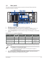
1.4 Rear panel
The system rear panel includes the power connector and several I/O ports that allow
convenient connection of devices.
1. Microphone port (pink). This port connects to a microphone.
2. Line Out port (lime). This port connects to a headphone or speaker. In a 4, 5.1, or
7.1-channel conguration, the function of this port becomes Front Speaker Out.
3. Line In port (light blue). This port connects to a tape, CD, DVD player, or other audio
sources.
Audio 2, 4, 5.1 or 7.1-channel configuration
Port Headset
2-channel 4-channel 5.1-channel 7.1-channel
Light Blue (Rear panel) Line In Rear Speaker Out Rear Speaker Out Rear Speaker Out
Lime (Rear panel) Line Out Front Speaker Out Front Speaker Out Front Speaker Out
Pink (Rear panel) Mic In Mic In Bass/Center Bass/Center
Lime (Front panel) — — — Side Speaker Out*/
Headphone
Pink (Front panel) — — — Mic In*/
Side Speaker Out
* Multi-streaming is disabled by default, and the Lime (front panel) jack may be used as Side Speaker Out. If multi-
streaming is enabled, the Lime (front panel) jack will support headphone, and Pink (front panel) jack will support
Side Speaker Out.
To configure a 7.1-channel audio output:
Use a chassis with HD audio module in the front panel to support a
7.1-channel audio output.
4. USB 3.2 Gen 2 (up to 10Gbps) ports (teal blue, Type-A). These 9-pin Universal
Serial Bus (USB) ports are for USB 3.2 Gen 2 devices.

1-6 Chapter 1: System introduction
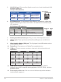
6. 2.5G Ethernet port. This port allows 2.5Gbps Ethernet connection to a Local Area
Network (LAN) through a network hub. Refer to the table below for the Ethernet port
LED indications.
2.5G LAN port LED indications
LAN port
Speed
LED
Activity Link
LED
Activity/Link LED Speed LED
Status Description Status Description
Off No link OFF No link
Green Linked Green 2.5 Gbps connection
Blinking Data activity Orange 1 Gbps/100Mbps/10Mbps connection
7. PS/2 Keyboard/Mouse Combo port. This port is for a PS/2 keyboard or mouse.
8. USB 2.0 ports. These 4-pin Universal Serial Bus (USB) ports are for USB 2.0/1.1
devices.
9. Video Graphics Adapter (VGA) port. This 15-pin port is for a VGA monitor or other
VGA-compatible device.
10. DisplayPorts. These ports are for DisplayPort-compatible devices.
11. COM port. This port connects a modem or other device that conforms with serial
specication.
RS232 RS485 RS422
Pin1 DCD B T(B)
Pin2 RXD A T(A)
Pin3 TXD NC R(A)
Pin4 DTR NC R(B)
Pin5 GND GND GND
Pin6 DSR NC NC
Pin7 RTS NC NC
Pin8 CTS NC NC
Pin9 RI/5V/12V NC/5V/12V NC/5V/12V
12. HDMITM port. This port is for a High-Denition Multimedia Interface (HDMITM)
connector, and is HDCP compliant allowing playback of HD DVD, Blu-ray, and other
protected content.
13. Power supply unit fan vent. This vent is for the PSU fan that provides ventilation
inside the power supply unit.
5. LAN (RJ-45) port. This port allows Gigabit connection to a Local Area Network (LAN)
through a network hub.
Activity/Link LED Speed LED
Status Description Status Description
OFF No link OFF 10Mbps connection
ORANGE Linked ORANGE 100Mbps connection
BLINKING Data activity GREEN 1Gbps connection LAN port
SPEED LED
ACT/LINK LED
LAN port LED indications

1-7
ASUS EBE-4U
14. Expansion slot brackets. Remove the expansion slot bracket when installing an
expansion card.
15. Parallel ports (optional). These 25-pin ports connect parallel printers, scanners, or
other devices.
16. USB 3.2 Gen 2 (up to 10Gbps) port (USB Type-C®). This 9-pin Universal Serial Bus
3.2 (USB 3.2) port is for USB 3.2 Gen 2 Type-C® devices.
17. Air vents. These vents allow air ventilation.
18. Serial ports (optional). These 9-pin COM ports are for pointing devices or other serial
devices.
19. Power connector. Plug the power cord to this connector.
RATING: 115/230Vac, 50/60Hz, 6A/3A (WW)
115Vac, 60Hz, 6A (TW)
220Vac, 50Hz, 3A (China)

1-8 Chapter 1: System introduction
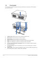
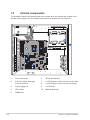
1.5 Internal components
The illustration below is the internal view of the system when you remove the chassis cover
and the power supply unit. The installed components are labeled for your reference.
1. Front panel cover
2. 5.25-inch optical drive bays
3.5-inch drive bay
3. Power supply unit
4. CPU socket
5. DIMM slots
6. ASUS motherboard
7. 2 x PCI Express 3.0/2.0 x16 slots (x16 mode)
8. 3 x PCI Express 3.0/2.0 x4 slots (x4 mode)
9. 2 x PCI slots
10. Metal bracket lock

This chapter provides details about the motherboard that comes with
the system. This chapter includes the motherboard layout, jumper
settings, and connector locations.
Motherboard information
Chapter 2

Chapter 2: Motherboard information
2-2
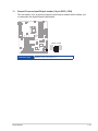
2.1 Before you proceed
Take note of the following precautions before you install motherboard components or change
any motherboard settings.
CAUTION!
• Unplug the power cord from the wall socket before touching any component.
• Before handling components, use a grounded wrist strap or touch a safely grounded
object or a metal object, such as the power supply case, to avoid damaging them due
to static electricity.
• Hold components by the edges to avoid touching the ICs on them.
• Whenever you uninstall any component, place it on a grounded antistatic pad or in the
bag that came with the component.
• Before you install or remove any component, always remove the AC power by
unplugging the power cord from the power outlet. Failure to do so may cause severe
damage to the motherboard, peripherals, or components.

ASUS EBE-4U 2-3
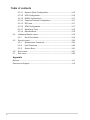
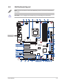
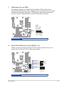
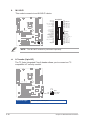
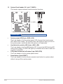
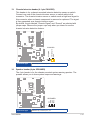
2.2 Motherboard layout
NOTE: Place nine screws into the holes indicated by circles to secure the motherboard to
the chassis.
CAUTION! Do not overtighten the screws! Doing so can damage the motherboard.
PCIEX4_1
PCIEX4_2
PCIEX4_3
PCI_2
PCI_1
SPEAKER
SATA6G_4
128Mb
BIOS
SATA6G_3 SATA6G_2 SATA6G_1
CHASSIS
AT_ATX_SEL
SPDIF_OUT
WDT_EN
CLRTC
F_PANEL
USB1011
I2C
BUZZER
M.2(WIFI)
LPT
AAFP
TPM
EATXPWR
CPU_FAN CHA_FAN2
CHA_FAN3
CHA_FAN1
BATTERY
PCIEX16_1
PCIEX16_2
Super
I/O
ASM
1083
ASM1480
ASM1480
ASM1480
ASM1480
ASM1480
ASM1480
ALC
897
24.4cm(9.6in)
LGA1200
Intel®
Q470E
Intel®
I219LM
DDR4 DIMM_A1 (64bit, 288-pin module)
2242
2280 2260 2242
2260 30522280 2242
3042
M.2_PCH_(SKT3)
M.2_PCH_(SKT2)
M.2_PCH_(SOCKET3)
PCIE SATA IRST
X4 V V
DDR4 DIMM_A2 (64bit, 288-pin module)
DDR4 DIMM_B1 (64bit, 288-pin module)
DDR4 DIMM_B2 (64bit, 288-pin module)
AUDIO
KBMS_USB89
COM1
HDMI
LAN1_U32G2_2
U32G2_C1
LAN2_U32G2_34
SATA6G_6
SATA6G_5
COM1_SEL
EATX12V
30.5cm(12in)
USB_INTERNAL_13
U32G1_67
USB_INTERNAL_12
COM2 COM3
COM2_SEL
COM4 COM5 COM6
LPC_DEBUG
DIS_ME
GPIO_CON
DP2
DP1
VGA
NANO_SIM
1 432 65 33
1
1516177
7
28
2
8
3
11
10
9
12
13
14
20 20 2012324 11 18192122
29
26
26
27
25
28
29
Place this side
towards the rear
of the chassis

Chapter 2: Motherboard information
2-4
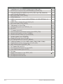
Connectors/Jumpers/Slots Page
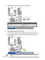
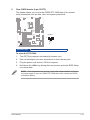
1. COM RING/+5V/+12V selection jumper (6-pin COM1_SEL) 2-11
2. EATX Power connectors (24-pin EATXPWR, 8-pin EATX12V) 2-16
3. CPU and Chassis Fan headers (4-pin CPU_FAN, 4-pin CHA_FAN1/2/3) 2-16
4. Intel® LGA1200 CPU socket 2-5
5. M.2 socket 3 (M.2_PCH_(SKT3)) 2-17
6. DDR4 DIMM slots 2-10
7. USB 2.0 connectors / header (USB_INTERNAL_12, USB_INTERNAL_13,
USB1011)
2-17
8. USB 3.2 Gen 1 header (20-1 pin U32G1_67) 2-18
9. M.2 socket 2 (M.2_PCH_(SKT2)) 2-18
10. TPM header (14-1 pin TPM) 2-19
11. SATA 6.0Gb/s ports (7-pin SATA6G_1-6) 2-19
12. M.2 Wi-Fi 2-20
13. I2C header (6-pin I2C) 2-20
14. General Purpose Input/Output header (10-pin GPIO_CON) 2-21
15. System Panel header (10-1 pin F_PANEL) 2-22
16. Chassis Intrusion header (4-1 pin CHASSIS) 2-23
17. Speaker header (4-pin SPEAKER) 2-23
18. Disable ME jumper (3-pin DIS_ME) 2-11
19. LPC Debug header (10-1 pin LPC_DEBUG) 2-24
20. COM Port headers (10-1 pin COM2, COM3, COM4, COM5, COM6) 2-24
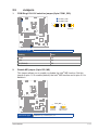
21. AT/ATX Mode selection jumper (3-pin AT_ATX_SEL) 2-12
22. WDT Enable jumper (2-pin WDT_EN) 2-12
23. LPT header (26-1 pin LPT) 2-25
24. Front Panel Audio header (10-1 pin AAFP) 2-25
25. Clear CMOS header (2-pin CLRTC) 2-13
26. PCI slots
27. Digital Audio header (4-1 pin SPDIF_OUT) 2-26
28. PCI Express 3.0/2.0 x4 slots
29. PCI Express 3.0/2.0 x16 slots
La pagina si sta caricando...
La pagina si sta caricando...
La pagina si sta caricando...
La pagina si sta caricando...
La pagina si sta caricando...
La pagina si sta caricando...
La pagina si sta caricando...
La pagina si sta caricando...
La pagina si sta caricando...
La pagina si sta caricando...
La pagina si sta caricando...
La pagina si sta caricando...
La pagina si sta caricando...
La pagina si sta caricando...
La pagina si sta caricando...
La pagina si sta caricando...
La pagina si sta caricando...
La pagina si sta caricando...
La pagina si sta caricando...
La pagina si sta caricando...
La pagina si sta caricando...
La pagina si sta caricando...
La pagina si sta caricando...
La pagina si sta caricando...
La pagina si sta caricando...
La pagina si sta caricando...
La pagina si sta caricando...
La pagina si sta caricando...
La pagina si sta caricando...
La pagina si sta caricando...
La pagina si sta caricando...
La pagina si sta caricando...
La pagina si sta caricando...
La pagina si sta caricando...
La pagina si sta caricando...
La pagina si sta caricando...
La pagina si sta caricando...
La pagina si sta caricando...
La pagina si sta caricando...
La pagina si sta caricando...
La pagina si sta caricando...
La pagina si sta caricando...
La pagina si sta caricando...
La pagina si sta caricando...
La pagina si sta caricando...
La pagina si sta caricando...
La pagina si sta caricando...
La pagina si sta caricando...
La pagina si sta caricando...
-
 1
1
-
 2
2
-
 3
3
-
 4
4
-
 5
5
-
 6
6
-
 7
7
-
 8
8
-
 9
9
-
 10
10
-
 11
11
-
 12
12
-
 13
13
-
 14
14
-
 15
15
-
 16
16
-
 17
17
-
 18
18
-
 19
19
-
 20
20
-
 21
21
-
 22
22
-
 23
23
-
 24
24
-
 25
25
-
 26
26
-
 27
27
-
 28
28
-
 29
29
-
 30
30
-
 31
31
-
 32
32
-
 33
33
-
 34
34
-
 35
35
-
 36
36
-
 37
37
-
 38
38
-
 39
39
-
 40
40
-
 41
41
-
 42
42
-
 43
43
-
 44
44
-
 45
45
-
 46
46
-
 47
47
-
 48
48
-
 49
49
-
 50
50
-
 51
51
-
 52
52
-
 53
53
-
 54
54
-
 55
55
-
 56
56
-
 57
57
-
 58
58
-
 59
59
-
 60
60
-
 61
61
-
 62
62
-
 63
63
-
 64
64
-
 65
65
-
 66
66
-
 67
67
-
 68
68
-
 69
69


in altre lingue
- English: Asus EBE-4U User manual
Documenti correlati
-
Asus EBE-4U Manuale utente
-
-
-
-
-
-
-
-
-