Videotec MAXIMUS MVXT Manuale del proprietario
- Tipo
- Manuale del proprietario

EN
English - Instruction manual
IT
Italiano - Manuale di istruzioni
FR
Français - Manuel d’instructions
DE
Deutsch - Bedienungsanleitung
RU
Русский - Руководство по эксплуатации
PT
Português - Manual de instruções
KO
한국어 - 지침 설명서
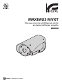
ITALIANO
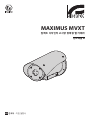
MAXIMUS MVXT
High-spec ex-proof thermal camera in a compact design
Manual B


EN
English - Instruction manual
ENGLISH
MAXIMUS MVXT
High-spec ex-proof thermal camera in a compact design
Manual B

EN - English - Instruction manual
2 MNVCMVXTBCAM_1813_EN
Contents
ENGLISH 1
1 About this manual ....................................................................................................................3
1.1 Typographical conventions ................................................................................................................................................ 3
2 Notes on copyright and information on trademarks .............................................................3
3 Identification .............................................................................................................................3
3.1 Product marking ..................................................................................................................................................................... 3
4 Installation ................................................................................................................................4
4.1 Range of use ............................................................................................................................................................................. 4
4.2 Connection of the power supply line .............................................................................................................................. 4
4.3 Connection of the Ethernet cable .................................................................................................................................... 5
4.4 Signal cable connection ....................................................................................................................................................... 5
4.4.1 Alarm and relay connections ...............................................................................................................................................................5
4.4.1.1 Connecting an alarm with dry contact .................................................................................................................................................................... 5
4.4.1.2 Relays connection ...........................................................................................................................................................................................................6
5 Switching on .............................................................................................................................6
5.1 Before powering the product in an explosive atmosphere .................................................................................... 6
5.2 First start-up ............................................................................................................................................................................. 6
6 Configuration ............................................................................................................................7
6.1 Default IP address................................................................................................................................................................... 7
6.2 Web interface ........................................................................................................................................................................... 7
6.2.1 First access to the web pages ..............................................................................................................................................................7
7 Accessories ................................................................................................................................ 7
8 Instructions for normal operation ...........................................................................................7
8.1 Special controls ....................................................................................................................................................................... 7
9 Maintenance .............................................................................................................................8
9.1 Firmware updating ................................................................................................................................................................ 8
9.1.1 Factory Default ......................................................................................................................................................................................... 8
10 Information on disposal and recycling ................................................................................. 8
11 Troubleshooting .....................................................................................................................8
12 Technical data .........................................................................................................................9
12.1 Cameras ................................................................................................................................................................................... 9

Instruction manual - English - EN
3MNVCMVXTBCAM_1813_EN
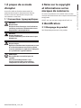
1 About this manual
Read all the documentation supplied carefully before
installing and using this unit. Keep the manual in a
convenient place for future reference.
1.1 Typographical conventions
DANGER!
High level hazard.
Risk of electric shock. Disconnect the
power supply before proceeding with any
operation, unless indicated otherwise.
DANGER!
Explosion hazard.
Read carefully to avoid danger of explosion.
CAUTION!
Medium level hazard.
This operation is very important for the
system to function properly. Please read
the procedure described very carefully and
carry it out as instructed.
INFO
Description of system specifications.
We recommend reading this part carefully
in order to understand the subsequent
stages.
2 Notes on copyright and
information on trademarks
The mentioned names of products or companies are
trademarks or registered trademarks.
ONVIF® is a trademark of Onvif, Inc.
3 Identification
3.1 Product marking
See the label attached to the product.

EN - English - Instruction manual
4 MNVCMVXTBCAM_1813_EN
4 Installation
CAUTION! Device installation and
maintaining must be performed by
specialist technical staff only.
The external multi-polar cable shield
(armature) must be earthed.
All disconnected wires must be electrically
isolated.
The product comes with a multi-polar cable
or a cable tail for coupling purposes. When
installing the device with the multi-polar
cable, keep at least 250mm free space from
the bottom of the housing to allow for the
minimum curvature radius of the multi-
polar cable.
4.1 Range of use
For installation indoors and outdoors.
Installation temperature: from -40°C (-40°F) up to
+60°C (140°F).
Operating temperature:
• Cold start from -40°C to +65°C.
• Operation from -50°C to +65°C.
Relative humidity: from 10% up to 95% (no
condensation).
4.2 Connection of the power
supply line
Electrical connections must be performed
with the power supply disconnected and
the circuit-breaker open.
When commencing installation make sure
that the specifications for the power supply
for the installation correspond with those
required by the device.
Check that the power supply is adequately
dimensioned.
The device can be provided with different power
supply voltages. The power supply voltage is
indicated on the product identification label. (3.1
Product marking, page 3).
The multicore cable has the power and earth cables
inside.
Perform the connections following the instructions
reported in the table .
CONNECTION OF THE POWER SUPPLY LINE
Power supply 24Vac/ 24Vdc/ 12Vdc
Colour Terminals
Black 1 (+) L (Phase)
Black 2 (-) N (Neutral)
Yellow/Green
Tab. 1

Instruction manual - English - EN
5MNVCMVXTBCAM_1813_EN
4.3 Connection of the Ethernet
cable
The Ethernet cable shield must always be
earthed via the connector. Always use a
shielded RJ45 connector.
Use of Ethernet cables with the following
characteristics is highly recommended:
• STP (shielded)
• Category 5E (or higher)
The product can be directly connected to an Ethernet
switch.
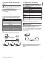
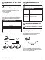
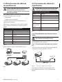
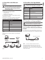
Carry out the connections as described in the table
(according to the standard specifications: TIA/EIA-
568-B).
CONNECTION OF THE ETHERNET CABLE
Pin number Cable color
1 Orange-White
2 Orange
3 Green-White
4 Blue
5 Blue-White
6 Green
7 Brown-White
8 Brown
Tab. 2
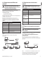
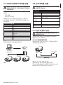
The example below shows a typical installation.
Switch
Personal
Computer
Fig. 1
4.4 Signal cable connection
CAUTION! TNV-1 installation type. The
installation is type TNV-1, do not connect it
to SELV circuits.
SIGNAL CABLE CONNECTION
Colour Function
White RS-485 A (+)
Yellow RS-485 B (-)
Pink Relay 1, Terminal A
Violet (blue, cable
tail version)
Relay 1, Terminal B
Red (brown, cable
tail version)
Alarm/Digital input
Green GND/Common alarm
Grey Reset
Tab. 3
4.4.1 Alarm and relay connections
The external relay and alarm cable shield
must be earthed.
The unit is equipped with the alarms and relays
indicated in the table (Tab. 3, page 5).
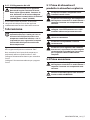
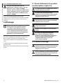
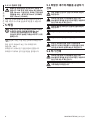
4.4.1.1 Connecting an alarm with dry contact
In case of free contact alarm make the connection as
shown in the figure.
AL1 COM
Dry contact
Fig. 2 AL1: Alarm 1. COM: Common alarms.
Clean contact of the alarm can be set NO (normally
open) or NC (normally closed) using the web
interface.

EN - English - Instruction manual
6 MNVCMVXTBCAM_1813_EN
4.4.1.2 Relays connection
The relays are usable with the specifications
described below. Working voltage: up
to 30Vac or 60Vdc. Current: 1A max. Use
suitable cable sections with the following
characteristics: from 0.25mm² (23AWG) up
to 1.5mm² (15AWG).
Due to the absence of polarity, both terminals of the
same relay can be connected either to alternating or
direct current voltages.
5 Switching on
The automatic pre-heating procedure (De-
Ice) activates for 2 hours if on device switch
on an ambient temperature is detected
under -10 °C (+14°F). The procedure is
necessary to guarantee correct operation of
the devices even at low temperatures.
The full functionality of the product is guaranteed
from the following ambient temperature: -40°C.
Do not turn on the unit when the ambient
temperature is lower than indicated: -40°C.
The unit is switched on by connecting the power
supply.
To switch off the unit disconnect the power.
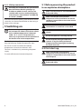
5.1 Before powering the product
in an explosive atmosphere
Make sure that all parts are fastened down
firmly and safely.
Make sure that the unit and other
components of the installation are closed
so that it is impossible to come into contact
with live parts.
Make sure that the device has been
connected to an earth link as described.
Ensure the rear cover plate is correctly
closed.
Ensure the product is correctly closed.
Ensure that the sealing of cable entry
systems (if any) has been performed
properly and the time of glue hardening
has been observed.
5.2 First start-up
Make sure that the unit and other
components of the installation are closed
so that it is impossible to come into contact
with live parts.
Make sure that all parts are fastened down
firmly and safely.

Instruction manual - English - EN
7MNVCMVXTBCAM_1813_EN
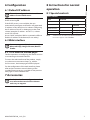
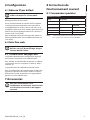
6 Configuration
6.1 Default IP address
The unit is configured to obtain an IP
address from a DHCP server.
The IP address acquired via DHCP is visible in the
DHCP server log file.
If the DHCP server is not available, the unit
automatically configures itself with a self-generated
IP address in the 169.254.x.x/16 subnet. Configuring
the IP address of the PC as belonging to the same
subnet (example: IP address: 169.254.1.1, subnet
mask: 255.255.0.0).
Use an ONVIF compliant VMS or a network sniffer to
find the IP address of the device (IP scan utility).
6.2 Web interface
Browsers supported (the latest version):
Microsoft Edge, Google Chrome, Mozilla
Firefox.
6.2.1 First access to the web pages
The first operation in configuring the device consists
in connecting to the web interface.
To access the web interface of the product, simply
use a browser to connect to http:/ ip_address.
On first access, the Home page will be displayed.
For the configuration of the web interface, please
refer to the instruction manual relating to the
installed firmware version, available on the product
web page on www.videotec.com.
7 Accessories
For further details on configuration and
use, refer to the manual of the relevant
accessory or support.
8 Instructions for normal
operation
8.1 Special controls
SPECIAL CONTROLS
Action Command
Protocol
HTTP API ONVIF (auxiliary
command)
Reboot the device
√¹
–
Relé On – tt:Relay1|On
Relé Off – tt:Relay1|Off
Tab. 4 ¹ Command can be enabled, for further information
contact the support centre VIDEOTEC.

EN - English - Instruction manual
8 MNVCMVXTBCAM_1813_EN
9 Maintenance
The pre-installed camera can only be
replaced with one of the same brand and
model.
Read the product Manual A before
performing any operation.
Please provide the device serial number when
requesting any replacement parts.
9.1 Firmware updating
Firmware upgrading can be carried out
directly on the web interface.
If necessary it is possible to update the device
firmware.
For further information please contact the VIDEOTEC
service center.
9.1.1 Factory Default
It is possible to reset to the factory default settings.
Follow the procedure below:
• Switch off the unit.
• Connect the signal cable grey and green wires (
Tab. 3, page 5).
• Power the unit.
• Wait 30 seconds.
• Disconnect the previously connected green and
grey wires.
• Wait for 2 minutes.
• Switch off the unit.
• Power the unit.
Once the factory default procedure has
terminated, you need to configure the unit
as described in the relevant chapter (6.1
Default IP address, page 7).
10 Information on disposal
and recycling
The European Directive 2012/19/EU on Waste
Electrical and Electronic Equipment (WEEE) mandates
that these devices should not be disposed of in the
normal flow of municipal solid waste, but they should
be collected separately in order to optimize the
recovery stream and recycling of the materials that
they contain and to reduce the impact on human
health and the environment due to the presence of
potentially hazardous substances.
The symbol of the crossed out bin is marked
on all products to remember this.
The waste may be delivered to appropriate collection
centers, or may be delivered free of charge to the
distributor where you purchased the equipment at
the time of purchase of a new equivalent or without
obligation to a new purchase for equipment with size
smaller than 25cm (9.8in).
For more information on proper disposal of these
devices, you can contact the responsible public
service.
11 Troubleshooting
Contact an authorized support centre if the
problems listed below persist or you have
any other issues that are not described
here.
Read the product Manual A before
performing any operation.
PROBLEM Video streaming is not visible.
CAUSE Incorrect IP address settings.
SOLUTION Check the device IP address
and the configuration of the
computer network card.
CAUSE Automatic preheating
procedure (De-Ice) in progress.
SOLUTION Wait until the end of the pre-
heating procedure. If the ambient
temperature is too low the unit
will remain blocked.

Instruction manual - English - EN
9MNVCMVXTBCAM_1813_EN
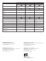
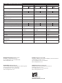
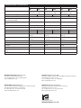
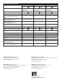
12 Technical data
For the technical data of the housing, consult Manual A of the product.
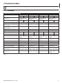
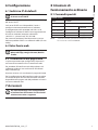
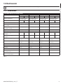
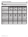
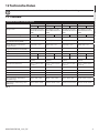
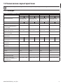
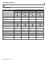
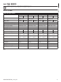
12.1 Cameras
THERMAL CAMERAS RESOLUTION 336X256
Lens 9mm Lens 13mm Lens 19mm Lens 25mm
PAL NTSC PAL NTSC PAL NTSC PAL NTSC
Image Device Uncooled VOx micro
-
bolometer
Uncooled VOx micro-
bolometer
Uncooled VOx micro-
bolometer
Uncooled VOx micro-
bolometer
Interpolated resolution 720x576 720x480 720x576 720x480 720x576 720x480 720x576 720x480
Pixel dimensions 17m 17m 17m 17m
Spectral response - long wave
infrared (LWIR)
from 7.5m to 13.5m from 7.5m to 13.5m from 7.5m to 13.5m from 7.5m to 13.5m
Internal shutter (only for sensor
compensation)
Video stop < 1sec. Video stop < 1sec. Video stop < 1sec. Video stop < 1sec.
Digital Detail Enhancement (DDE)
√ √ √ √
Digital Zoom 2x, 4x 2x, 4x 2x, 4x 2x, 4x
Image updating frequency 8.3fps 7.5fps 8.3fps 7.5fps 8.3fps 7.5fps 8.3fps 7.5fps
Image updating high frequency 25fps 30fps 25fps 30fps 25fps 30fps 25fps 30fps
Scene range (High Gain) -40°C ÷ +160°C (-40°F ÷
+320°F)
-40°C ÷ +160°C (-40°F ÷
+320°F)
-40°C ÷ +160°C (-40°F ÷
+320°F)
-40°C ÷ +160°C (-40°F ÷
+320°F)
Scene range (Low Gain) -40°C ÷ +550°C (-40°F ÷
+1022°F)
-40°C ÷ +550°C (-40°F ÷
+1022°F)
-40°C ÷ +550°C (-40°F ÷
+1022°F)
-40°C ÷ +550°C (-40°F ÷
+1022°F)
Horizontal field of view 35° 25° 17° 13°
Vertical field of view 27° 19° 13° 10°
F-number F/1.25 F/1.25 F/1.25 F/1.1
Thermal sensitivity (NEdT) < 50mK at f/1.0 < 50mK at f/1.0 < 50mK at f/1.0 < 50mK at f/1.0
Person (detection / recognition /
identification)
285m / 71m / 36m
(935ft / 233ft / 118ft)
440m / 112m / 56m
(1443ft / 2368ft / 183ft)
640m / 160m / 80m
(2099ft / 524ft / 262ft)
930m / 230m / 116m
(3051ft / 754ft / 380ft)
Auto (detection / recognition /
identification)
880m / 220m / 108m
(2887ft / 722ft / 354ft)
1340m / 340m / 170m
(4396ft / 1115ft / 557ft)
1950m / 500m / 250m
(6397ft/ 1640ft/ 820ft)
2800m / 710m / 360m
(9186ft / 2329ft /
1181ft)
Tab. 5

EN - English - Instruction manual
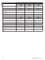
10 MNVCMVXTBCAM_1813_EN
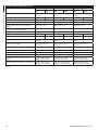
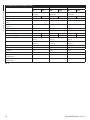
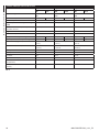
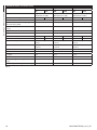
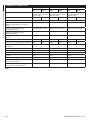
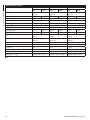
THERMAL CAMERAS RESOLUTION 336X256
Lens 35mm Lens 50mm Lens 60mm
PAL NTSC PAL NTSC PAL NTSC
Image Device Uncooled VOx microbolo
-
meter
Uncooled VOx microbolo
-
meter
Uncooled VOx microbolo
-
meter
Interpolated resolution 720x576 720x480 720x576 720x480 720x576 720x480
Pixel dimensions 17m 17m 17m
Spectral response - long wave infrared (LWIR) from 7.5m to 13.5m from 7.5m to 13.5m from 7.5m to 13.5m
Internal shutter (only for sensor compen
-
sation)
Video stop < 1sec. Video stop < 1sec. Video stop < 1sec.
Digital Detail Enhancement (DDE)
√ √ √
Digital Zoom 2x, 4x 2x, 4x 2x, 4x
Image updating frequency 8.3fps 7.5fps 8.3fps 7.5fps 8.3fps 7.5fps
Image updating high frequency 25fps 30fps 25fps 30fps 25fps 30fps
Scene range (High Gain) -40°C ÷ +160°C (-40°F ÷
+320°F)
-40°C ÷ +160°C (-40°F ÷
+320°F)
-40°C ÷ +160°C (-40°F ÷
+320°F)
Scene range (Low Gain) -40°C ÷ +550°C (-40°F ÷
+1022°F)
-40°C ÷ +550°C (-40°F ÷
+1022°F)
-40°C ÷ +550°C (-40°F ÷
+1022°F)
Horizontal field of view 9,3° 6,5° 5,5°
Vertical field of view 7,1° 5° 4,2°
F-number F/1.2 F/1.2 F/1.25
Thermal sensitivity (NEdT) < 50mK at f/1.0 < 50mK at f/1.0 < 50mK at f/1.0
Person (detection / recognition / identifi
-
cation)
1280m / 320m / 160m
(4199ft / 1050ft / 525ft)
1700m / 430m / 215m
(5577ft / 1410ft / 715ft)
2000m / 510m / 255m
(6561ft / 1673ft / 836ft)
Auto (detection / recognition / identification) 3850m / 950m / 295m
(12631ft / 3116ft / 967ft)
5100m / 1320m / 660m
(16732ft / 4330ft / 2165ft)
6000m / 1560m / 780m
(19685ft / 5118ft / 2559ft)
Tab. 6

Instruction manual - English - EN
11MNVCMVXTBCAM_1813_EN
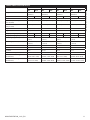
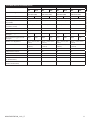
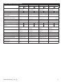
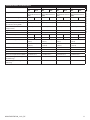
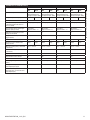
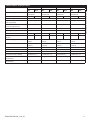
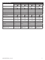
THERMAL CAMERAS RESOLUTION 640X512
Lens 9mm Lens 13mm Lens 19mm Lens 25mm
PAL NTSC PAL NTSC PAL NTSC PAL NTSC
Image Device Uncooled VOx micro
-
bolometer
Uncooled VOx micro
-
bolometer
Uncooled VOx micro
-
bolometer
Uncooled VOx micro
-
bolometer
Interpolated resolution 720x576 720x480 720x576 720x480 720x576 720x480 720x576 720x480
Pixel dimensions 17m 17m 17m 17m
Spectral response - long wave
infrared (LWIR)
from 7.5m to 13.5m from 7.5m to 13.5m from 7.5m to 13.5m from 7.5m to 13.5m
Internal shutter (only for sensor
compensation)
Video stop < 1sec. Video stop < 1sec. Video stop < 1sec. Video stop < 1sec.
Digital Detail Enhancement (DDE)
√ √ √ √
Digital Zoom 2x, 4x, 8x 2x, 4x, 8x 2x, 4x, 8x 2x, 4x, 8x
Image updating frequency 8.3fps 7.5fps 8.3fps 7.5fps 8.3fps 7.5fps 8.3fps 7.5fps
Image updating high frequency 25fps 30fps 25fps 30fps 25fps 30fps 25fps 30fps
Scene range (High Gain) -40°C ÷ +160°C (-40°F ÷
+320°F)
-40°C ÷ +160°C (-40°F ÷
+320°F)
-40°C ÷ +160°C (-40°F ÷
+320°F)
-40°C ÷ +160°C (-40°F ÷
+320°F)
Scene range (Low Gain) -40°C ÷ +550°C (-40°F ÷
+1022°F)
-40°C ÷ +550°C (-40°F ÷
+1022°F)
-40°C ÷ +550°C (-40°F ÷
+1022°F)
-40°C ÷ +550°C (-40°F ÷
+1022°F)
Horizontal field of view 69° 45° 32° 25°
Vertical field of view 56° 37° 26° 20°
F-number F/1.4 F/1.25 F/1.25 F/1.1
Thermal sensitivity (NEdT) < 50mK at f/1.0 < 50mK at f/1.0 < 50mK at f/1.0 < 50mK at f/1.0
Person (detection / recognition /
identification)
250m / 63m / 31m
(820ft / 207ft / 102ft)
390m / 95m / 47m
(1280ft / 312ft / 154ft)
570m / 144m / 72m
(1870 / 472 / 236ft)
820m / 210m / 104m
(2690ft / 689ft / 341ft)
Auto (detection / recognition /
identification)
720m / 175m /88m
(2362 / 574 / 289ft)
1080m / 275m / 140m
(3543ft / 902ft / 459ft)
1550m / 400m / 200m
(5085ft / 1312ft / 656ft)
2200m / 580m / 290m
(7218ft / 1903ft / 951ft)

MNVCMVXTBCAM_1813_EN
THERMAL CAMERAS RESOLUTION 640X512
Lens 35mm Lens 50mm Lens 60mm
PAL NTSC PAL NTSC PAL NTSC
Image Device Uncooled VOx microbolo
-
meter
Uncooled VOx microbolo
-
meter
Uncooled VOx microbolo
-
meter
Interpolated resolution 720x576 720x480 720x576 720x480 720x576 720x480
Pixel dimensions 17m 17m 17m
Spectral response - long wave infrared (LWIR) from 7.5m to 13.5m from 7.5m to 13.5m from 7.5m to 13.5m
Internal shutter (only for sensor compen
-
sation)
Video stop < 1sec. Video stop < 1sec. Video stop < 1sec.
Digital Detail Enhancement (DDE)
√ √ √
Digital Zoom 2x, 4x, 8x 2x, 4x, 8x 2x, 4x, 8x
Image updating frequency 8.3fps 7.5fps 8.3fps 7.5fps 8.3fps 7.5fps
Image updating high frequency 25fps 30fps 25fps 30fps 25fps 30fps
Scene range (High Gain) -40°C ÷ +160°C (-40°F ÷
+320°F)
-40°C ÷ +160°C (-40°F ÷
+320°F)
-40°C ÷ +160°C (-40°F ÷
+320°F)
Scene range (Low Gain) -40°C ÷ +550°C (-40°F ÷
+1022°F)
-40°C ÷ +550°C (-40°F ÷
+1022°F)
-40°C ÷ +550°C (-40°F ÷
+1022°F)
Horizontal field of view 18° 12.4° 10.4°
Vertical field of view 14° 9.9° 8.3°
F-number F/1.2 F/1.2 F/1.25
Thermal sensitivity (NEdT) < 50mK at f/1.0 < 50mK at f/1.0 < 50mK at f/1.0
Person (detection / recognition / identifi
-
cation)
1140m / 280m / 142m
(3740ft / 919ft / 466ft)
1500m / 380m / 190m
(4921ft / 1247ft / 623ft)
1750m / 450m / 225m
(5741ft / 1476ft / 738ft)
Auto (detection / recognition / identification) 3000m / 800m / 200m
(9843ft / 2625ft / 656ft)
3900m / 1060m / 540m
(12795ft / 3478ft / 1772)
4500m / 1240m / 640m
(14764ft / 4068ft / 2100ft)
Headquarters Italy Videotec S.p.A.
Via Friuli, 6 - I-36015 Schio (VI) - Italy
Tel. +39 0445 697411 - Fax +39 0445 697414
Email: [email protected]
France Videotec France SARL
Immeuble Le Montreal, 19bis Avenue du Québec, ZA de Courtaboeuf
91140 Villebon sur Yvette - France
Tel. +33 1 60491816 - Fax +33 1 69284736
Email: info.fr@videotec.com
Asia Pacific Videotec (HK) Ltd
Flat 8, 19/F. On Dak Industrial Building, No. 2-6 Wah Sing Street
Kwai Chung, New Territories - Hong Kong
Tel. +852 2333 0601 - Fax +852 2311 0026
Email: info.hk@videotec.com
Americas Videotec Security, Inc.
Gateway Industrial Park, 35 Gateway Drive, Suite 100
Plattsburgh, NY 12901 - U.S.A.
Tel. +1 518 825 0020 - Fax +1 518 825 0022
Email: info.usa@videotec.com
www.videotec.com

IT
Italiano - Manuale di istruzioni
ITALIANO
MAXIMUS MVXT
Telecamera termica antideflagrante ad alte
prestazioni dal design compatto
Manuale B

IT - Italiano - Manuale di istruzioni
2 MNVCMVXTBCAM_1813_IT
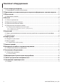
Sommario
ITALIANO 1
1 Informazioni sul presente manuale ........................................................................................3
1.1 Convenzioni tipografiche .................................................................................................................................................... 3
2 Note sul copyright e informazioni sui marchi commerciali ...................................................3
3 Identificazione ..........................................................................................................................3
3.1 Marcatura del prodotto ........................................................................................................................................................ 3
4 Installazione ..............................................................................................................................4
4.1 Campo di utilizzo .................................................................................................................................................................... 4
4.2 Collegamento della linea di alimentazione .................................................................................................................. 4
4.3 Collegamento del cavo di rete Ethernet ........................................................................................................................ 5
4.4 Collegamento dei cavi di segnale .................................................................................................................................... 5
4.4.1 Collegamento degli allarmi e dei relè ..............................................................................................................................................5
4.4.1.1 Collegamento allarme con contatto pulito ............................................................................................................................................................5
4.4.1.2 Collegamento dei relè ...................................................................................................................................................................................................6
5 Accensione ................................................................................................................................6
5.1 Prima di alimentare il prodotto in atmosfera esplosiva............................................................................................ 6
5.2 Prima accensione .................................................................................................................................................................... 6
6 Configurazione .........................................................................................................................7
6.1 Indirizzo IP di default............................................................................................................................................................. 7
6.2 Interfaccia web ........................................................................................................................................................................ 7
6.2.1 Primo accesso alle pagine web ...........................................................................................................................................................7
7 Accessori ....................................................................................................................................7
8 Istruzioni di funzionamento ordinario ...................................................................................7
8.1 Comandi speciali .................................................................................................................................................................... 7
9 Manutenzione ...........................................................................................................................8
9.1 Aggiornamento del firmware ............................................................................................................................................ 8
9.1.1 Factory Default ......................................................................................................................................................................................... 8
10 Informazioni sullo smaltimento e il riciclo ...........................................................................8
11 Risoluzione dei problemi ....................................................................................................... 8
12 Dati tecnici ..............................................................................................................................9
12.1 Telecamere ............................................................................................................................................................................. 9

Manuale di istruzioni - Italiano - IT
3MNVCMVXTBCAM_1813_IT
1 Informazioni sul presente
manuale
Prima di installare e utilizzare questa unità, leggere
attentamente tutta la documentazione fornita. Tenere
il manuale a portata di mano per consultazioni
successive.
1.1 Convenzioni tipografiche
PERICOLO!
Pericolosità elevata.
Rischio di scosse elettriche. Prima di
eseguire qualsiasi operazione assicurarsi di
togliere tensione al prodotto, salvo diversa
indicazione.
PERICOLO!
Pericolo di esplosione.
Leggere attentamente per evitare pericoli
di esplosione.
ATTENZIONE!
Pericolosità media.
L'operazione è molto importante per il
corretto funzionamento del sistema. Si
prega di leggere attentamente la procedura
indicata e di eseguirla secondo le modalità
previste.
INFO
Descrizione delle caratteristiche del
sistema.
Si consiglia di leggere attentamente per
comprendere le fasi successive.
2 Note sul copyright e
informazioni sui marchi
commerciali
I nomi di prodotto o di aziende citati sono marchi
commerciali o marchi commerciali registrati
appartenenti alle rispettive società.
ONVIF® è un marchio di proprietà di Onvif, Inc.
3 Identificazione
3.1 Marcatura del prodotto
Vedere l’etichetta posta sul prodotto.

IT - Italiano - Manuale di istruzioni
4 MNVCMVXTBCAM_1813_IT
4 Installazione
ATTENZIONE! L'installazione e la
manutenzione del dispositivo devono
essere eseguite solo da personale tecnico
specializzato.
La calza esterna del cavo multipolare
(armatura) deve essere collegata a terra.
Isolare elettricamente tutti i cavi non
collegati.
Il prodotto è provvisto di un cavo
multipolare o di una coda libera di cavi
che permette di effettuare i collegamenti.
Nel caso del cavo multipolare, durante
l'installazione del dispositivo tenere
almeno 250mm di spazio libero dal fondo
della custodia per rispettare il raggio di
curvatura minimo del cavo multipolare.
4.1 Campo di utilizzo
Installazione per interni ed esterni.
Temperatura di installazione: da -40°C fino a +60°C.
Temperatura di esercizio:
• Partenza a freddo da -40°C fino a +65°C.
• In funzionamento da -50°C fino a +65°C.
Umidità relativa: da 10% fino a 95% (senza condensa).
4.2 Collegamento della linea di
alimentazione
Eseguire le connessioni elettriche in
assenza di alimentazione e con dispositivo
di sezionamento aperto.
All’atto dell’installazione controllare che
le caratteristiche di alimentazione fornite
dall’impianto corrispondano a quelle
richieste dal dispositivo.
Verificare che la sorgente di alimentazione
sia adeguatamente dimensionata.
Al dispositivo possono essere fornite diverse
tensioni di alimentazione. Il valore di tensione di
alimentazione è riportato nell'etichetta identificativa
del prodotto (3.1 Marcatura del prodotto, pagina 3).
Nel cavo multipolare sono presenti i cavi di
alimentazione e di messa a terra.
Effettuare i collegamenti secondo quanto descritto
nella tabella.
COLLEGAMENTO DELLA LINEA DI ALIMENTAZIONE
Alimentazione 24Vac/ 24Vdc/ 12Vdc
Colore Morsetti
Nero 1 (+) L (Fase)
Nero 2 (-) N (Neutro)
Giallo/Verde
Tab. 1

Manuale di istruzioni - Italiano - IT
5MNVCMVXTBCAM_1813_IT
4.3 Collegamento del cavo di rete
Ethernet
La calza del cavo Ethernet deve sempre
essere collegata a terra tramite il
connettore. Utilizzare sempre un
connettore RJ45 di tipo schermato.
Si raccomanda l'utilizzo di cavi Ethernet con le
seguenti caratteristiche:
• STP (schermato)
• Categoria 5E (o superiore)
Il prodotto può essere collegato direttamente ad uno
switch Ethernet.
Effettuare i collegamenti secondo quanto descritto
nella tabella (in accordo con lo standard: TIA/EIA-
568-B).
COLLEGAMENTO DEL CAVO DI RETE ETHERNET
Numero del pin Colore del cavo
1 Arancione-Bianco
2 Arancione
3 Verde-Bianco
4 Blu
5 Blu-Bianco
6 Verde
7 Marrone-Bianco
8 Marrone
Tab. 2
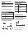
Una installazione tipica è quella riportata
nell’esempio sottostante.
Switch
Personal
Computer
Fig. 1
4.4 Collegamento dei cavi di
segnale
ATTENZIONE! L'installazione è di tipo TNV-1.
Non collegare a circuiti SELV.
COLLEGAMENTO DEI CAVI DI SEGNALE
Colore Funzione
Bianco RS-485 A (+)
Giallo RS-485 B (-)
Rosa Relè 1, Terminale A
Viola (blu, versione
con coda di cavi)
Relè 1, Terminale B
Rosso (marrone,
versione con coda
di cavi)
Allarme/Ingresso digitale
Verde GND/Comune allarme
Grigio Reset
Tab. 3
4.4.1 Collegamento degli allarmi e dei
relè
La calza esterna del cavo allarmi e relè deve
essere collegata a terra.
L’unità è dotata degli allarmi e dei relè riportati in
tabella (Tab. 3, pagina 5).
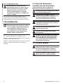
4.4.1.1 Collegamento allarme con contatto
pulito
Nel caso di allarme a contatto pulito eseguire il
collegamento come illustrato in figura.
AL1 COM
Contatto pulito
Fig. 2 AL1: Allarme 1. COM: Comune allarmi.
Il contatto pulito di allarme può essere impostato
NO (normalmente aperto) oppure NC (normalmente
chiuso) tramite l'interfaccia web.

IT - Italiano - Manuale di istruzioni
6 MNVCMVXTBCAM_1813_IT
4.4.1.2 Collegamento dei relè
I relè sono utilizzabili con le specifiche
descritte di seguito. Tensione di lavoro:
fino a 30Vac oppure 60Vdc. Corrente: 1A
max. Utilizzare cavi di sezione adeguata
con le seguenti caratteristiche: da 0.25mm²
(23AWG) fino a 1.5mm² (15AWG).
A causa dell’assenza di polarità, ad entrambi
i terminali del relè possono essere applicate
indifferentemente tensioni alternate o continue.
5 Accensione
La procedura di preriscaldamento
automatico (De-Ice) si attiva per 2 ore se
all’accensione il dispositivo rileva una
temperatura ambiente inferiore a -10 °C.
La procedura serve a garantire la corretta
funzionalità del dispositivo anche alle
basse temperature.
È garantita la completa funzionalità del prodotto
dalla seguente temperatura ambiente: -40°C.
Non accendere l'unità quando la temperatura
ambiente è inferiore a quella indicata: -40°C.
Collegare l’alimentazione elettrica per accendere
l'unità.
Scollegare l’alimentazione elettrica per spegnere
l'unità.
5.1 Prima di alimentare il
prodotto in atmosfera esplosiva
Assicurarsi che tutti i componenti siano
installati in modo sicuro.
Assicurarsi che l'unità e gli altri componenti
dell’impianto siano chiusi in modo idoneo a
impedire il contatto con componenti sotto
tensione.
Assicurarsi che l’apparecchio sia stato
collegato a un allacciamento a terra nelle
modalità indicate nel presente manuale.
Assicurarsi che il fondo posteriore sia
chiuso correttamente.
Assicurarsi che il prodotto sia chiuso
correttamente.
Assicurarsi che la sigillatura dei sistemi di
entrata cavi (se presente) sia stata eseguita
correttamente lasciando agire il preparato
per la sigillatura fino all’indurimento
completo.
5.2 Prima accensione
Assicurarsi che l'unità e gli altri componenti
dell’impianto siano chiusi in modo idoneo a
impedire il contatto con componenti sotto
tensione.
Accertarsi che tutte le parti siano fissate in
maniera solida ed affidabile.
La pagina si sta caricando...
La pagina si sta caricando...
La pagina si sta caricando...
La pagina si sta caricando...
La pagina si sta caricando...
La pagina si sta caricando...
La pagina si sta caricando...
La pagina si sta caricando...
La pagina si sta caricando...
La pagina si sta caricando...
La pagina si sta caricando...
La pagina si sta caricando...
La pagina si sta caricando...
La pagina si sta caricando...
La pagina si sta caricando...
La pagina si sta caricando...
La pagina si sta caricando...
La pagina si sta caricando...
La pagina si sta caricando...
La pagina si sta caricando...
La pagina si sta caricando...
La pagina si sta caricando...
La pagina si sta caricando...
La pagina si sta caricando...
La pagina si sta caricando...
La pagina si sta caricando...
La pagina si sta caricando...
La pagina si sta caricando...
La pagina si sta caricando...
La pagina si sta caricando...
La pagina si sta caricando...
La pagina si sta caricando...
La pagina si sta caricando...
La pagina si sta caricando...
La pagina si sta caricando...
La pagina si sta caricando...
La pagina si sta caricando...
La pagina si sta caricando...
La pagina si sta caricando...
La pagina si sta caricando...
La pagina si sta caricando...
La pagina si sta caricando...
La pagina si sta caricando...
La pagina si sta caricando...
La pagina si sta caricando...
La pagina si sta caricando...
La pagina si sta caricando...
La pagina si sta caricando...
La pagina si sta caricando...
La pagina si sta caricando...
La pagina si sta caricando...
La pagina si sta caricando...
La pagina si sta caricando...
La pagina si sta caricando...
La pagina si sta caricando...
La pagina si sta caricando...
La pagina si sta caricando...
La pagina si sta caricando...
La pagina si sta caricando...
La pagina si sta caricando...
La pagina si sta caricando...
La pagina si sta caricando...
La pagina si sta caricando...
La pagina si sta caricando...
La pagina si sta caricando...
La pagina si sta caricando...
La pagina si sta caricando...
La pagina si sta caricando...
-
 1
1
-
 2
2
-
 3
3
-
 4
4
-
 5
5
-
 6
6
-
 7
7
-
 8
8
-
 9
9
-
 10
10
-
 11
11
-
 12
12
-
 13
13
-
 14
14
-
 15
15
-
 16
16
-
 17
17
-
 18
18
-
 19
19
-
 20
20
-
 21
21
-
 22
22
-
 23
23
-
 24
24
-
 25
25
-
 26
26
-
 27
27
-
 28
28
-
 29
29
-
 30
30
-
 31
31
-
 32
32
-
 33
33
-
 34
34
-
 35
35
-
 36
36
-
 37
37
-
 38
38
-
 39
39
-
 40
40
-
 41
41
-
 42
42
-
 43
43
-
 44
44
-
 45
45
-
 46
46
-
 47
47
-
 48
48
-
 49
49
-
 50
50
-
 51
51
-
 52
52
-
 53
53
-
 54
54
-
 55
55
-
 56
56
-
 57
57
-
 58
58
-
 59
59
-
 60
60
-
 61
61
-
 62
62
-
 63
63
-
 64
64
-
 65
65
-
 66
66
-
 67
67
-
 68
68
-
 69
69
-
 70
70
-
 71
71
-
 72
72
-
 73
73
-
 74
74
-
 75
75
-
 76
76
-
 77
77
-
 78
78
-
 79
79
-
 80
80
-
 81
81
-
 82
82
-
 83
83
-
 84
84
-
 85
85
-
 86
86
-
 87
87
-
 88
88


Videotec MAXIMUS MVXT Manuale del proprietario
- Tipo
- Manuale del proprietario
in altre lingue
Documenti correlati
-
Videotec MAXIMUS MVXT Manuale del proprietario
-
-
-
-
-
-
Videotec NXPTZR SERIES2 Manuale utente
-
Videotec MAXIMUS MPX SERIES2 Manuale utente
-
-
