

genius
ENGLISH
pag.2
CONTENTS
1 INTRODUCTION .............................................................................................................3
2 OPERATIVE PRINCIPLES..............................................................................................3
3 DECRIPTION...................................................................................................................6
3.1 FRONTAL PANEL...............................................................................................6
3.2 BACK PANEL......................................................................................................7
4 JUMPER SETTING AND FUNCTIONS...........................................................................8
4.1 INDEPENDENT, MASTER AND SLAVE.............................................................8
4.2 EXTERNAL CONTROLS ....................................................................................9
4.3 EXPANDER BUS................................................................................................9
4.4 AUDIO DETECTOR..........................................................................................10
4.5 LED 1/16...........................................................................................................10
4.6 MULTIPLAY......................................................................................................10
4.7 PRE-EMPHASIS E 19 KHz (INPUT B)..............................................................10
4.8 OUTPUT LEVEL ...............................................................................................11
4.9 PLUG AUTOFADER (OPTIONAL)....................................................................11
4.10 JUMPER SUMMARY........................................................................................11
5 REMOTE INTERFACE..................................................................................................13
6 EXPANDER BUS...........................................................................................................13
7 INSTALLATION AND CONNECTIONS .........................................................................14
7.1 INPUTS.............................................................................................................15
7.2 OUTPUTS.........................................................................................................16
8 APPLICATIONS.............................................................................................................17
8.1 BI-CHANNEL SWITCHER ................................................................................17
8.2 EMERGENCY SWITCHER...............................................................................17
8.3 MPX SWITCHER ..............................................................................................17
9 TECHNICAL SPECIFICATIONS....................................................................................18
10 WARRANTY ..................................................................................................................18
11 TECHNICAL DOCUMENTATION..................................................................................19

genius
ENGLISH
pag.3
1 INTRODUCTION
•
genius
is a multifunction switcher with several applications: its different configurations
depend form the way the jumpers inside the equipment are set.
genius
can be used in
the following ways:
- manual or remote switcher
- audio detector with automatic switching
- balancing equipment with level setting
- audio distributor
- bi-channel splitting system or double MPX
- audio emergency system
- autofader system
•
genius
immediateness makes its use simple allowing remote control too.
•
genius
solves all the problems which can occur in all audio signal applications, deleting
every risky connection and assuring a safe and easy switching.
• Its features and conception have been studied to support its different applications at the
best:
- balanced inputs and outputs with very high S/N ratio to assure disturb immunity even in
difficult conditions while using long wires.
- EXPANDER BUS connector studied for cascade connection of several genius.
- Remote interface with optoisolated input and output controls and a section of relé
contacts.
For all these simple but useful peculiar features
genius
can be considered a genial
equipment.
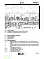
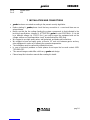
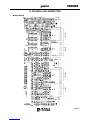
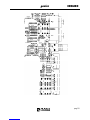
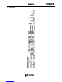
2 OPERATIVE PRINCIPLES
genius
is a multifunction switcher with several applications: its different configurations depend
form the way the jumpers inside the equipment are set.
genius
features two electronically balanced inputs on XLR with DRAW plugs to withdraw
output service signals.
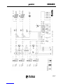
The A input can use the XLR signal (INDEPENDENT USE) or the EXPANDER BUS
(MASTER or SLAVE) signal, as shown in the block diagram.
The default setting is INDIPENDENT USE to allow the equipment to work independently, if
there is not a specific customer’s request.
The A input features a ±10 dB amplifying section set through the potentiometer on the front
panel.
The B input structure is different: it features a 50 μsec pre-emphasis and a 19 kHz sinusoid
oscillator, both set trough jumper.

genius
ENGLISH
pag.4
The B input features a ±10 dB amplifying section set through the potentiometer on the front
panel, too.
The frontal panel selector can select 3 operative modes with the following features:
• AUTO: it allows remote control and the Auto Detector system can directly switch on B
channel if audio is missing on A channel. If external controls are missing the A inputs are
directed to the output.
• A: manual mode (MAN led lighted) A input is directed to the output: remote control and
audio detector cannot switch signals.
• B: manual mode (MAN led lighted) B input is directed to the output: remote control and
audio detector cannot switch signals
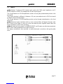
genius
features a bypass hardware which, in case of power problems or failure, will bypass
through a relé, the A input in the output.
The two R and L outputs are electronically balanced on XLR trough specific BUFFERS able to
control impedance up to 600 Ω, the two DRAW plugs withdraw output service signals.
The outputs can work at 0 dB or at +6 dB according to the used standard (setting through
internal jumper).
The EXPANDER BUS is used only for cascade connection of several
genius
in a chain, in
which you need to distribute the signal A and/or RDS of one of them (MASTER) on the other
A inputs (SLAVE) connected to the external BUS.
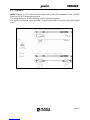
When used as MPX splitter,
genius
features an RDS input which is distributed and set on the
two outputs.
With several
genius
connected in cascade the RDS signal the RDS signal can be injected or
withdrawn from the EXPANDER BUS.
genius
features an Audio Detector circuit able to verify the presence of an audio signal on one
of the two input channels and if correctly set, it commutes one channel on another one, by
closing relé and optoisolated contacts on the remote connector.
A well conceived philosophy allows
genius
to run external switching controls coming from
other automated systems.


genius
ENGLISH
pag.6
3 DECRIPTION
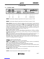
3.1 FRONTAL PANEL
À GAIN A: Potentiometer setting the signal level on the A input, it controls ±10 dB.
Á GAIN B: Potentiometer setting the signal level on the B input, it controls ±10 dB.
 Audio detector: device able to detect the white in the selected signal; it spots when the
sound does not reach the set threshold (see THR). When the white is detected the 1/16 led
starts blinking according to the number of times set (see Led 1/16). If the white lasts
longer than 16 blinking, the Audio Detector goes TIME OUT (if jumper J21 and J22 are
inserted) and commutes from the A to the B inputs till the A level does not come back to
the threshold value (see jumper Audio Detector, chapter 4.4).
N.B. see jumper setting in chapter 4.
THR: multi-turn trimmer; it sets the Audio Detector threshold from –20 dB to –6 dB by
turning anti-clockwise. The trimmer turns 20 times (it does not stop), the standard blinking
threshold is set at –20 dB.
TIME: multi-turn trimmer; it sets the led length from 0 to 20 sec turning anti-clockwise. The
trimmer turns 20 times (it does not stop), the standard blinking time is set at 1 sec.
Led 1/16: it blinks when the selected signal level does not reach the threshold value. You
can set the number of blinks that the led need to realise before the Audio Detect goes to
TIME OUT (see jumper led 1/16, chapter 4.5).
à Switcher: it selects the operative mode.
Led AUTO: lights out when the switcher is in auto position.
AUTO: it allows
genius
remote control and the Audio Detector system can automatically
switch on B channel when there is no audio signal in A.
When external controls are missing the A inputs are directed to the output.
A: manual mode (led MAN lit), the A input is directed to the output and the remote control
and the audio detector cannot switch.
B: manual mode (led MAN lit), the B input is directed to the output and remote control and
the audio detector cannot switch.
Led Man: it lights out when the switcher is in A or B position.
Ä Led A L: it shows the presence of left A input in the left OUT output.

genius
ENGLISH
pag.7
Å Led A R: it shows the presence of right A input in the right OUT output.
Æ Led B L: it shows the presence of left B input in the left OUT output.
Ç Led B R: it shows the presence of right B input in the right OUT output.
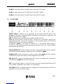
3.2 BACK PANEL
À ON/OFF switch: it switches on the equipment, the led inside shows the status of the
equipment. If the led is off and the switch is ON please check the power supply wire and
the PWS protection fuse integrity
VDE: net power supply standard plug ( using the provided net wire)
Fuse: the fuse box houses 2 fuses 100 mA T, the first one is connected in series to the
primary feed while the second one is stockpile. In case the primary feed is not 220/230 but
110/115 the fuse does not need to be replaced.
ATTENTION:
genius
is set ex-work at 220/230 VAC, if the network power supply is
110/115 VAC, you need to open the equipment and set the feed circuit tension modifier
placed behind the VDE plug.
Á Remote INTERFACE: interface 25 pole connector to input and output controls needed to
connect any external equipment controlling or to be controlled by
genius
.
 Expander BUS: 9 pole connector to connect in chain other
genius
, the BUS transfers
simultaneously signals and controls to all the equipment in the chain.
à RDS input: BNC connector which injects the RDS signal in the outputs, this connection is
used only when
genius
works in MPX split mode.
Ä OUT: Left and Right outputs on 3 pole XLR male connectors electronically balanced, PIN
OUT standard configuration (see chapter 7 for connections).
Å OUT DRAW: PIN RCA unbalanced output, it supplies the same signal present in OUT; we
suggest to use it only as service output.

genius
ENGLISH
pag.8
Æ B IN: Left and Right inputs on connectors 3 pole XLR female connectors electronically
balanced, PIN OUT standard configuration.
Ç OUT DRAW: PIN RCA unbalanced output, it supplies the same signal present in B IN ; we
suggest to use it as service output.
È A IN: Left and Right inputs on connectors 3 pole XLR female connectors electronically
balanced, PIN OUT standard configuration.
É OUT DRAW: PIN RCA unbalanced output, it supplies the same signal present in A IN; we
suggest to use it as service output.
4 JUMPER SETTING AND FUNCTIONS
4.1 INDEPENDENT, MASTER AND SLAVE
genius
can operate in INDIVIDUAL mode or in CHAIN, with several
genius
connected trough
an external BUS (see chapter 6).
The RDS, A left and A right signals can be withdrawn from their corresponding input
connectors placed on the back panel or from the External Bus connector.
This last solution is only used in the chain operative mode and distributes the signal on every
genius
without connecting them in parallel.
The A Left and A Right and RDS inputs have always to be set in one of the following ways:
• INDEPENDENT: it withdraws the signal form the input connector on the back panel and
ignores the one present on the Bus
• MASTER: it withdraws the signal form the input connector in the back panel and it injects it
in the Bus.
• SLAVE: it withdraws the signal form the Bus and ignore the one present on the input
connector.
Working with just 1
genius
the inputs must be set INDEPENDENT, while in chain you need to
distinguish between MASTER and SLAVE (and in the whole chain there must be just 1
equipment set as MASTER).
J5∩J6 A input Right channel INDEPENDENT.
J7∩J8 A input Left channel INDEPENDENT
J15∩J16 RDS input INDEPENDENT
J5+J6 A input Right channel MASTER.
J7+J8 A input Left channel MASTER.
J15+J16 RDS MASTER input.
J5 A input Right channel SLAVE.
J7 A input Left channel SLAVE.
J15 RDS input SLAVE.

genius
ENGLISH
pag.9
(N.B. J5∩J6 shows that you must insert the jumper between a contact in the J5 position and a
contact in the J6; J5+J6 shows that you need to insert 2 jumpers, one in J5 and another one
in J6).
4.2 EXTERNAL CONTROLS
It is possible to connect external controls, to the Remote Interface, to remote A into B input
switching and mix A and B on the outputs (MIX control). Even if the controls are connected,
in order for them to work,
genius
should be in AUTO mode (see switcher on front panel).
Independently of the external control presence, when the switcher is not in AUTO position, the
signal MANUAL ERROR is sent to Remote Interface special contacts.
By connecting an external alarm system to these contacts the operator is informed that the
remote controls are disabled.
4.3 EXPANDER BUS
The Expander Bus allows to easily connect several
genius
and distribute the signals and
controls to all of them without creating the connection in parallel among them.
Through this connector the external controls connected to the Remote Interface can be
injected and /or withdrawn from the external Bus which connects the equipment.
The controls which can be injected or withdrawn on the external Bus are:
• MIX: it mixes the signals on A (L and R) and on B (Land R) and send them on OUT (L and
R) output.
• COMMAND B Left: it commutes the A left and B left signals.
• COMMAND B Right: it commutes the A right and B right signals.
• MANUAL ERROR: it shows that one equipment in the chain is in MANUAL mode and the
external controls connected to its Remote Interface cannot work.
The signals which can be injected or withdrawn from the external Bus are:
• A left : see MASTER and SLAVE setting.
• A right: see MASTRE and SLAVE setting.
• RDS : see MASTRE and SLAVE setting.
An equipment connected to the BUS can inject and/or withdraw these controls from the BUS
in case the switcher on the front panel is in AUTO position and the following jumper are
inserted:
J17 It allows transmission/ reception on the BUS of the Manual Error.
J18 It allows transmission/ reception on the BUS of the commutation control from the
A left to the B left input.
J19 It allows transmission/ reception on the BUS of the MIX control.
J20 It allows transmission/ reception on the BUS of the commutation control of the A
Right and B Right input.

genius
ENGLISH
pag.10
4.4 AUDIO DETECTOR
J1 It sends the signal the Left channel of the A input to the Audio Detector adder .
J2 It sends the signal of the Right channel of the A input to the Audio Detector adder.
J3 It sends the signal of the Left channel of the B input to the Audio Detector adder.
J4 It sends the signal of the Right channel of the B input to the Audio Detector adder.
J21 It assigns to the Audio Detector the switching control from the A Left channel to the B
left channel in the B left (N.B. only in AUTO mode).
J22 It assigns to the Audio Detector the switching control from the A Right channel to
the B Right channel in the B Right (N.B. only in AUTO mode).
J23 It transforms from impulsive to stable the closure of the Audio Detector relé contacts on
the Remote Interface (stable with jumper inserted).
4.5 LED 1/16
J33 It sets 16 led blinks to show the white (standard).
J34 It sets 64 led blinks to show the white.
J35 It sets 128 led blinks to show the white.
J36 It sets 256 led blinks to show the white.
4.6 MULTIPLAY
The Multiplay is an oscillator which generates closure and open impulses; these can be
addressed to the Remote Interface and control the operation of the Audio Detector relé.
The Multiplay restarts when the Audio Detector remarks the white for a longer time than the
set one (see Auto Detector) and it stops when the signal level goes over the threshold again.
Every impulse lasts about 1 second.
J23+J24 The opening and the closure of the relé audio detect are controlled by the
Multiplay.
J25 It sets 1 second of closure and 1 second of opening.
J26 It sets 1 second of closure and 3 seconds of opening.
J27 It sets 1 second of closure and 7 seconds of opening.
J28 It sets 1 second of closure and 15 seconds of opening.
J29 It sets 1 second of closure and 31 seconds of opening.
4.7 PRE-EMPHASIS E 19 KHz (INPUT B)
J9 It inserts the pre-emphasis in the signal of the Right channel in the B input.
J11 It inserts the pre-emphasis in the signal of the Left channel in the B input.
J10 It overlaps the 19 KHz to the –20dB to the signal of the Right channel of the B input.
J12 It overlaps the 19 KHz to the –20dB to the signal of the Right channel of the B input.
See Note at the following page

genius
ENGLISH
pag.11
NOTE! Apart from closing Jumpers J10 e J12, to enable the 19 KHz tone when Input B is
selected You need to establish again the R52 resistor which is located near IC 9 and behind
the INPUT B – RIGHT XLR connector on the rear board.
4.8 OUTPUT LEVEL
J13 It enlarges by +6 dB the level of the Right channel output.
J14 It enlarges by +6 dB the level of the Left channel output.
4.9 PLUG AUTOFADER (OPTIONAL)
J30 master/slave A right
J31 master slave A left
J32 stereo coupling
4.10 JUMPER SUMMARY
J1 It sends the signal the Left channel of the A input to the Audio Detector adder .
J2 It sends the signal of the Right channel of the A input to the Audio Detector
adder.
J3 It sends the signal of the Left channel of the B input to the Audio Detector adder.
J4 It sends the signal of the Right channel of the B input to the Audio Detector
adder.
J5 A input Right channel SLAVE.
J5+J6 A input Right channel MASTER.
J5∩J6 A input Right channel INDEPENDENT.
J7 A input Left channel SLAVE.
J7+J8 A input Left channel MASTER.

genius
ENGLISH
pag.12
J7∩J8 A input Left channel INDEPENDENT
J9 It inserts the pre-emphasis in the signal of the Right channel in the B input.
J11 It inserts the pre-emphasis in the signal of the Left channel in the B input.
J10 It overlaps the 19 KHz to the –20dB to the signal of the Right channel of the B
input.
J12 It overlaps the 19 KHz to the –20dB to the signal of the Right channel of the B
input.
J13 It enlarges by +6 dB the level of the Right channel output.
J14 It enlarges by +6 dB the level of the Left channel output.
J15∩J16 RDS input INDEPENDENT
J15+J16 RDS MASTER input.
J15 RDS input SLAVE.
J17 It allows transmission/ reception on the BUS of the Manual Error.
J18 It allows transmission/ reception on the BUS of the commutation control from the
A left to the B left input.
J19 It allows transmission/ reception on the BUS of the MIX control.
J20 It allows transmission/ reception on the BUS of the commutation control of the A
Right and B Right input.
J21 It assigns to the Audio Detector the switching control from the A Left channel to
the B left channel in the B left (N.B. only in AUTO mode).
J22 It assigns to the Audio Detector the switching control from the A Right channel to
the B Right channel in the B Right (N.B. only in AUTO mode).
J23 It transforms from impulsive to stable the closure of the Audio Detector relé
contacts on the Remote Interface (stable with jumper inserted).
J23+J24 The opening and the closure of the relé audio detect are controlled by the
Multiplay.
J25 It sets 1 second of closure and 1 second of opening.
J26 It sets 1 second of closure and 3 seconds of opening.
J27 It sets 1 second of closure and 7 seconds of opening.
J28 It sets 1 second of closure and 15 seconds of opening.
J29 It sets 1 second of closure and 31 seconds of opening.
J30 master/slave A right
J31 master slave A left
J32 stereo coupling
J33 It sets 16 led blinks to show the white (standard).
J34 It sets 64 led blinks to show the white.
J35 It sets 128 led blinks to show the white.
J36 It sets 256 led blinks to show the white.
P1 Trimmer to set the RDS signal level on the Right output.
P2 Trimmer to set the RDS signal level on the Left output.
P3 Trimmer to set the internal oscillator level at 19 KHz sinusoid associated to the
B-Right output.
P4 Trimmer to set the internal oscillator level at 19 KHz internal sinusoid associated
to the B-Left output.
P7 Trimmer to set the internal oscillator frequency at 19 KHz sinusoid.
P12 Trimmer to set the switching time.

genius
ENGLISH
pag.13
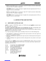
5 REMOTE INTERFACE
Interface to connect the commands for the remote control of some functions of the
genius
and
to control equipment connected to it.
Pin 1 manual error opto out (Emitter NPN optocopuler)
Pin 2 manual error opto out (Common NPN optocopuler)
Pin 3 multiplay opto out (Emitter NPN optocopuler)
Pin 4 multiplay opto out (Common NPN optocopuleR)
Pin 5 audio detect relè COMMON
Pin 6 audio detect relè NORMALY CLOSED
Pin 7 audio detect relè NORMALY OPEN
Pin 8 B left 1°relè NORMALY OPEN
Pin 9 B left 1°relè NORMALY CLOSED
Pin 10 B left 1°relè COMMON
Pin 11 B left 2°relè COMMON
Pin 12 B left 2°relè NORMALY CLOSED
Pin 13 B left 2°relè NORMALY OPEN
Pin 14 MIX command (Anode diodo optocopuler)
Pin 15 MIX command (Kathode diodo optocopuler)
Pin 16 B left command (Anode diodo optocopuler)
Pin 17 B left command (Kathode diodo optocopuler)
Pin 18 B right command (Anode diodo optocopuler)
Pin 19 B right command (Kathode diodo optocopuler)
Pin 20 GND
Pin 21 +15Vcc
Pin 22 –15Vcc
Pin 23 B right relè NORMALY OPEN
Pin 24 B right relè NORMALY CLOSED
Pin 25 B right relè COMMON
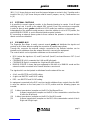
6 EXPANDER BUS
The extern Bus is used only in case there are several
genius
connected in chain. The
Expander Bus is the connector which allows reception and transmission of audio signal and
controls on the External Bus.
Pin 1 A right
Pin 2 A left
Pin 3 RDS
Pin 4 Left command B
Pin 5 Right command B
Pin 6 GND
Pin 7 GND

genius
ENGLISH
pag.14
Pin 8 Manual error
Pin 9 MIX
7 INSTALLATION AND CONNECTIONS
•
genius
has been conceived according to the present security legislation.
• Before starting Yr
genius
please check that any connection is correct and there are no
wire problems.
• Make sure that the line voltage feeding the system corresponds to that indicated in the
techìnical specifications (chapter 9). ATTENTION:
genius
is set at 220/230VAC, if it is fed
by a different voltage (ex. 110/115 VAC) you need to open the equipment and set the
volatge swithcer on the alimentation circuit, located behind the VDE plug.
• We suggest to use high quality wires, well protected, and balanced connections.
• We suggest to leave an empty space, at least a 19‘’ rack unit, between genius and any
other equipment in order not to alterate the operative temperature.
• The installation must be realised by skilled technicians.
• In case of technical problems or faults please do not open the box and contact AXEL
TECHNOLOGY.
• This manual images could differ a bit from yr
genius
real design.
• Please keep this instruction manual after reading it in detail.

genius
ENGLISH
pag.15
7.1 INPUTS
genius
features 2 balanced XLR female inputs active with 10KΩ input impedance, and 2
DRAW outputs on PIN RCA to withdraw the A and B input signals.
The A input features a ±10 dB amplification section set using the potentiometer placed on the
front panel.
The B input structure is different: it features a 50 μsec pre-emphasis and a 19 KHz sinusoid
oscillator, both set trough jumper.
The B input features a ±10 dB amplifying section set by through potentiometer on the front
panel, too.
genius
features a bypass hardware which, in case of power failure, will bypass through a relé,
the A input in the output; in case one of the two internal power supplies breaks down the
bypass hardware system starts operating.
genius
A inputs are set ex-works as INDEPENDENT and B inputs are without pre-emphasis
and 19 Khz; setting modifications are left to the user.
We always recommend, when possible, to realise balanced connections with good quality
wires.

genius
ENGLISH
pag.16
7.2 OUTPUTS
genius
features an XLR male balanced output active with 100Ω impedance and a DRAW
output on PIN RCA for general purposes.
The output features a +6 dB amplifying section controlled by jumper.
We always recommend, when possible, to realise balanced connections with good quality
wires.

genius
ENGLISH
pag.17
8 APPLICATIONS
genius
is a very flexible equipment and has many different application possibilities, according
to its different settings.
8.1 BI-CHANNEL SWITCHER
Its use as bi-channel or double mono switcher equipment does not require any internal
setting.
8.2 EMERGENCY SWITCHER
Its use as emergency switcher requires the enabling of the following functions and
connections:
1. Connect the source to be monitored to the A input.
2. Connect the emergency source to the B channel.
3. Enable the monitoring by the audio detector of the A input by inserting the J1 and J2
jumpers which send to the audio detector adder the Left A and Right A signals.
4. To modify the blinking time and frequency please take a look at the Audio Detector
section.
5. Insert the J21 and J22 to enable the commutation from the A to the B input; if you do not,
they will simply switch the audio detector relé and the multiplay photocoupler placed on
the remote door.
We suggest you to use the audio detector relé and the multiplay photocoupler to start the
equipment connected to the B input used as emergency source, or to connect it to
telecontrols to signal the presence of a problem.
The audio will be again commuted on the A input only when on the same A input it will be
present a signal for a longer time than the time set trough P12.
8.3 MPX SWITCHER
Its use as emergency switcher requires the enabling of the following functions and
connections:
1) Connect the network source to the A input
2) Connect the local source to the B input.
Both channels of the B input feature a 50 μsec pre-emphasis section and a 19 KHz settable
(sinusoid) section: to enable them you need to insert J9-J10-J11-J12 jumpers.
The BNC input for RDS allows its distribution on the two outputs, the internal trimmers P1 and
P2 allows setting of the different level on the two outputs.
By connecting more
genius
equipment it is possible to distribute the network and RDS signals
trough the expander BUS to different equipment.

genius
ENGLISH
pag.18
9 TECHNICAL SPECIFICATIONS
Input
Max level : +20dB
Bal. input common-mode rejection : 45dB 1KHz
Output
Max level : +20dB
Bal. output common-mode rejection : 45dB 1KHz
Linearity : ±0,1dB 0÷100KHz
Noise : -90dB
Mains voltage: 110/220 Vac, 50/60Hz
Consumption: 10VA
Working Temperature: -10÷50 °C
Dimension
Rackmounting: 482 x 215 x 44 mm ( 19’’ 1U )
Weight: 3,5 Kg
10 WARRANTY
The warranty covered by AXEL TECHNOLOGY S.R.L. has 1 year validity ex-work.
Do not open the equipment without being previously authorised by AXEL TECHNOLOGY, in
case of seal breaking the warranty will expire.
AXEL TECHNOLOGY will not be responsible for any damage, of any origin, caused or
related to an incorrect use of the product.


La pagina si sta caricando...
-
 1
1
-
 2
2
-
 3
3
-
 4
4
-
 5
5
-
 6
6
-
 7
7
-
 8
8
-
 9
9
-
 10
10
-
 11
11
-
 12
12
-
 13
13
-
 14
14
-
 15
15
-
 16
16
-
 17
17
-
 18
18
-
 19
19
-
 20
20
-
 21
21


