Eneo IED-62F0036P0A Quick Installation Manual
- Categoria
- Telecamere di sicurezza
- Tipo
- Quick Installation Manual
Questo manuale è adatto anche per

Quick Installation Guide
1/2.8” Network Dome, Fixed,
Day&Night, 1920x1080, Infrared
12VDC, PoE, Indoor
IED-62V2812P0B
EN
IT
FR
DE
IED-62F0036P0A

2
Table of contents
Parts supplied ...............................................................................................................5
Part names .....................................................................................................................6
Installation instructions ...............................................................................................7
Pan & Tilt adjustments .....................................................................................................................................................8
Zoom & focus adjustments (Vari-focal lens type) ..................................................................................................8
Installation and commissioning Instructions ..........................................................................................................9
Quick Network Setup ..................................................................................................10
Web viewer description .............................................................................................................................................. 11
Player control & Display ......................................................................................................................................... 11
User Manual ............................................................................................................................................................... 12
Setup Menu Table ..................................................................................................................................................... 13
Quick Setup .................................................................................................................15
Information ...................................................................................................................................................................... 15
Users ................................................................................................................................................................................... 15
Add ................................................................................................................................................................................ 16
Edit .................................................................................................................................................................................. 16
Delete ............................................................................................................................................................................ 17
Date & Time ..................................................................................................................................................................... 17
Current Time ............................................................................................................................................................... 17
New Time...................................................................................................................................................................... 17
Time Zone .................................................................................................................................................................... 17
Day & Time Display ................................................................................................................................................... 18
Network ............................................................................................................................................................................. 18
IPv4 Address ............................................................................................................................................................... 18
IPv6 Address ............................................................................................................................................................... 19
DNS ................................................................................................................................................................................ 19
Further information ....................................................................................................20

3
EN
Safety instructions
General safety instructions
•
• Keep the operating instructions in a safe place for later use.
• Installation, commissioning and maintenance of the system may only be carried out by authorised
individuals and in accordance with the installation instructions - ensuring that all applicable standards and
guidelines are followed.
• Protect the devices from water penetration and humidity, since these can cause lasting damage.
• Should moisture nevertheless enter the system, under no circumstance switch on the devices under these
conditions, instead send them for examination to an authorised specialist workshop.
•
• The device must be protected from excesses of heat, dust, humidity and vibration.
• When separating the system from the voltage supply, only ever use the plug to pull out the cable. Never
pull directly on the cable itself.
• Lay the connecting cables carefully and check that they are not mechanically stressed, kinked or damaged
and that no humidity can penetrate into them.
• In the event of a malfunction, please inform your supplier.
• Maintenance and repairs may only be carried out by authorised specialist personnel.
• The system must be isolated from the power supply before opening the housing.
•
warranty claim.
• Connection cables should always be exchanged through Videor E. Hartig GmbH.
• Use only original spare parts and accessories from Videor E. Hartig GmbH.
• The housing should only be cleaned using a mild domestic cleaning agent. Never use solvents or petrol as
these can permanently damage the surface.
• During installation, it is essential to ensure that the seals provided are correctly installed and that they are
not displaced during installation. Damaged seals must not be installed and will invalidate any warranty.
• The installer is responsible for the maintenance of the enclosure as per the technical data, e.g. by sealing
the cable outlets with silicone.
•
• The devices may only be operated in the temperature range indicated in the data sheet and within the
• The camera may never be pointed directly at the Sun with the aperture open (this will destroy the sensor).
• It is unavoidable that during manufacture and to a certain extent during later use, humidity will be present
may condense inside the housing.
• To avoid this condensation inside the very tightly sealed housing, the manufacturer has inserted silica gel
sachets in the housing of the various camera types.
• It is however a physical given, that these silica gel bags will reach saturation after a certain amount of time.
They should therefore be replaced with new silica gel sachets.
• During installation, it is essential to ensure that the seals provided are correctly installed and that they are
not displaced during installation. Damaged seals must not be installed and will invalidate any warranty.
• A multipolar, easily accessible isolation device should be installed in the proximity of the IR Spotlight, in
order to disconnect the device from the power supply for service work.
• The earth connection must be made according to the low impedance requirement of DIN VDE 0100.
• Subsequent painting of the equipment surface can impair the function.
• Any warranty claim is invalidated by subsequent painting.
• A safety margin of > 1m from the spotlight must be maintained when viewing directly into the IR Spotlight
in a darkened environment.
• Do not look directly at invisible LED radiation using optical instruments (e.g. a reading glass, magnifying
glass or microscope), since this can endanger the eyes, LED Class 1M.
• Operation of the IR spotlight with a defective cover or during repair is prohibited.

4
Class A device note
This is a Class A device. This device can cause malfunctions in the living area; in such an event, the operator may
need to take appropriate measures to compensate for these.
WEEE (Waste Electronical & Electronic Equipment)
Correct Disposal of This Product (Applicable in the European Union and other European countries with separate
collection systems).
This marking shown on the product or its literature, indicates that it should not be disposed with
other household wastes at the end of its working life. To prevent possible harm to the environment
or human health from uncontrolled waste disposal, please separate this from other types of wastes
and recycle it responsibly to promote the sustainable reuse of material resources. Household users
should contact either the retailer where they purchased this product, or their local government
Business users should contact their supplier and check the terms and conditions of the purchase
contract. This product should not be mixed with other commercial wastes for disposal.
Graphical symbols
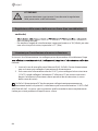
Please pay attention to the safety instructions, and carefully read through this instruction guide before initial
operation.
Important points of warning are marked with a caution symbol.
i
Important points of advice are marked with a notice symbol.

5
EN
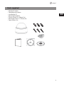
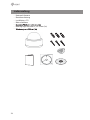
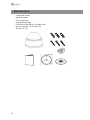
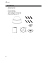
Parts supplied
• Network Camera
• Operating Instruction
• Installation CD
• Mounting Template
• Plastic Anchor: 6 x 30mm (3x)
• Mounting Screw: 4 x 25mm (3x)
• Open Driver (1x)

6
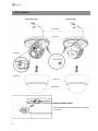
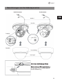
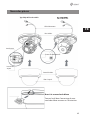
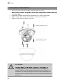
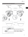
Part names
Open the dome cover
Turn the open key in the dome cover gap
as shown.
Fixed lens type
Zoom lever
Power Cable
Vari-focal lens type
Focus lever
Dome Cover
IP RESET button
Dome Base
Bubble Dome

7
EN
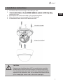
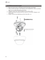
Installation instructions
1. Drill three holes for mounting on the ceiling or wall.
2.
mounting screws.
3. Route the power & ethernet cable to the connecting place.
4. Adjust the camera’s viewing angle (Pan, Tilt, Rotation)
5. Assemble the dome cover to the dome base unit.
CAUTION:
Extreme care should be taken NOT to scratch the lens and the
bubble dome surface while the camera installing or adjusting.
Care should be taken the cable is NOT to be damaged, kinked or
exposed in the hazardous area. Do not expose the camera direct-
ly to a strong light source such as the sun or spot light.
Plastic Anchor (6x30mm)
Mounting Screw (4x25mm)

8
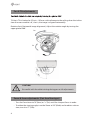
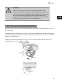
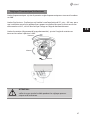
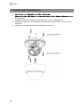
Pan & Tilt adjustments
Tilt limit: Tilt is limited to 25°min ~ 90°max. with reference to the ceiling when the inclina-
tion of camera module is 0°, that is, the image is aligned horizontally.
Rotation limit (Horizontal image alignment): Adjust the rotation angle by turning the
upper gimbal 360°.
CAUTION:
Be careful with the cable twisting during pan or tilt adjustments.
Zoom & focus adjustments (Vari-focal lens type)
• Turn the Focus lever to “N”(Near) or “∞”(Far) until the sharpest focus is made.
• To widen the viewing angle, turn the Zoom to “W”(Wide) and to obtain a closer
view, turn it to “T”(Tele)
Pan
Tilt
Rotation

9
EN
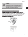
Installation and commissioning Instructions
properly, follow the order for applying power.
1. Plug the network cable into RJ-45 Ethernet Port. If PoE is the unique power, there
will be no need to connect Power jack.
2.
then plug the DC adapter to DC outlets to avoid an improper reset from power
jitter and a damage from the surge voltage when no load.
i
When PoE and Local DC power are connected at the same time, local power has pri-
ority. Camera can work with either DC12V or PoE(IEEE Std. 802.3af). Primary and second-
ary grounds are completely isolated to avoid the possible ground loop problems.

10
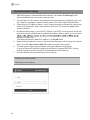
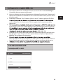
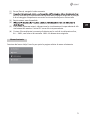
Quick Network Setup
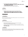
1. After the camera is connected to the network, start ‘eneo Site Manager’ tool
(downloadable from www.eneo-security.com).
2. You will get a list of cameras connected to the local network. Highlight your cam-
era in the list and open a context menu with a click of the right mouse button.
3. Select the „Set IP Address [dhcp / static]“ option to open a window for setting the
cameras IP properties. When you are done click the „OK“ button to update the
camera settings.
4. By default the camera is set to DHCP. If there is no DHCP server present in the net-
work the camera will fall back to a default IP address after a while. In this scenario
identical IP addresses.
The network camera‘s default IP address is: 192.168.1.10.
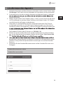
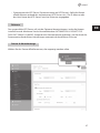
5. Right clicking the device name in the eneo Site Manager will bring up the context
menu. Use the ‘Open Device Web Site’ option to access the camera.
6. The web viewer login page will open up in your default web browser.
In case of Microsoft Internet Explorer install Active-X named VIDEOR E. Hartig
GmbH according to the instruction at the bottom of the browser.
7. Use the default user name and password to log in.
Default user name: admin
Default password: admin

11
EN
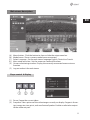
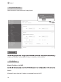
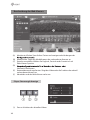
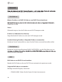
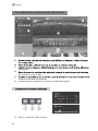
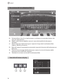
Web viewer description
(A) Menu button : Click the button to show or hide the setup menu bar.
(B) Model name : Show a camera model name connected.
(C) Select Language : Set the web viewer language English, Deutsch or French.
(D) Main setup menu bar : Set the camera or network functions.
(E) Camera monitoring window: Display the currently connected camera view or
function.
(F) Log out and exit the web viewer
Player control & Display
(1) Pause: Freeze the current video.
(2) Snapshot: Take a picture of the video image currently on display. Supports the or-
igin image size view, print, and save feature.Speaker: Enables audio to be output
to the audio out port.

12
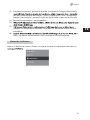
(3) Record: Not Available
(4)
(5)
returns to the previous view.
(6) Custom: Selects the live view display scale, 0%~200%, by the control bar. 100% is
the original size.
User Manual
Help the menu function. Click and pop-up the page about current menu description.

13
EN
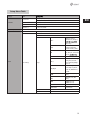
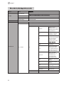
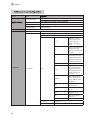
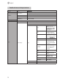
Setup Menu Table
Category Menu
LIVE VIEW
Player Control
Pause, Snapshot, Record (*)
Display (Window Fit, Full Screen, Custom)
Video Stream Stream1, Stream2, Stream3
Protocol HTTP, TCP, UDP
PTZ Contol (*) Zoom, Focus, Push AF
PLAYBACK (*) Event Search, Timeline Search, Timeline Bar
SETUP
Information General, System Information, Open source Information
Video & Image
Source
Stream1/2/3
Image
Basic
Brightness, Contrast,
Saturation, Hue, Sharpness,
mirror image
OSD
Enable text OSD, Enable
date&time OSD, Enable
zoom&focus OSD (*), Mode
AE
Mode, Shutter, Max shutter,
Gain, Max gain, Slow Shutter,
AWB Mode, Cb Gain, Cr Gain
AF (*)
Mode, Speed, Lens Locking,
Locking Timer, Lens Cali-
bration, Enable Day&Night
sync focus
Day&Night
Mode, Switching time,
Threshold (D->N), Thresh-
old (N->D), IR LED Control,
Smart IR
WDR
WDR(Mode, Level), Defog
(Mode)
BLC
BLC (Mode, Level), HLC
(Mode)
DNR
2DNR(Mode, Level),
3DNR(Mode, Level)
LDC Mode, Level, Boundary Line
VerticalView Mode, Rotation
Privacy Mask Color, Name
Digital Zoom Level
Auto iris,

14
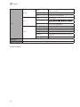
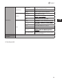
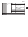
SETUP
Record (*)
Record
Overwrite when storage is full,
Continuous record setting
Schedule
Storage Format, Remove, Storage Information
Event
Triggers
Motion, VCA, Tamper, Alarm In, System, Manual, Network,
Timer, Day/Night
Actions
Server
Rules Event Processing, ONVIF Mapping
System
Security User, HTTPS, IP Filter, ONVIF, Video Stream, Export/Import
Date & Time Current Time, New Time, Time Zone, Date & Time Display
Network TCP/IP, DDNS, RTP, UPnP, Zeroconf, Bonjour
Language English, German , French, Polish, Finnish, Korean
Maintenance
Maintain (Restart, Reset, Default), Upgrade, Setup Export,
Setup Import
Log & Report Logs (Database Capacity, Search Condition, Log List), Report
USER MANUAL
LOG OUT
(*) Not Available

15
EN
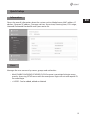
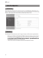
Quick Setup
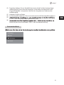
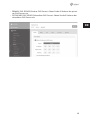
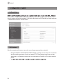
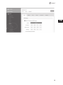
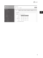
Information
Shows the overall information about the system such as Model name, MAC address, IP
address, Zeroconf, IP address, Firmware version, Server time, Running time, CPU usage,
Inbound/Outbound Bandwidth and Open source list.
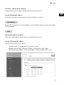
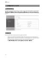
Users
Manages the user accounts by names, groups and authorities.
• Mark ENABLE ANONYMOUS VIEWR LOGIN if anyone is permitted to login anony-
mously. Accessing SETUP menu with the anonymous login will exit and require ID/
Password login.
• > USERS : Can be added, edited or deleted.

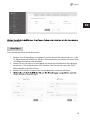
16
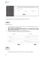
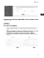
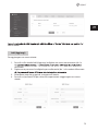
Click the Add, Edit, or Delete button for managing user account.
Add
To add a new user:
1. Click the Add tab, and type a new user name. (1 to 14 alphanumeric characters).
User names are not case sensitive.
2.
Passwords are case sensitive.
3. Select one of the groups you wish to assign to the user.
4. Click the OK button to save the settings and add a new user.
Edit
To edit a user:
1. Select one of the User Names in the User List you want to modify.

17
EN
2. Click the Edit tab, then new pop-up window appears.
3.
4. Select one of the groups you wish to assign to the user.
5. Click the OK button to save the settings and modify a user.
Delete
To delete a user:
1. Select one of the User Names in the User List you want to remove.
2.
3.
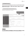
Date & Time
Current Time
Shows the current date and time. Clicking SAVE tap updates and saves the date and time
with the selected time in NEW TIME.
New Time
Select one of the following server time.
• Synchronize with computer time: Obtains the time from the computer.
• Set manually: Sets the date and time manually.
• Synchronize with NTP Server: Obtains the time from the assigned NTP server at
every hour in INTERVAL. The NTP server’s IP address or host name has to be speci-
Time Zone
Select the time zone to be referenced to the NTP server where the camera is installed
Mark AUTOMATICALLY ADJUST FOR DAYLIGHT SAVING CHANGES check box to update
the time automatically with daylight savings

18
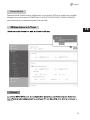
Day & Time Display
Select the date & time formats to be displayed.
Network
assigns an IP address to the device if there is a device on the network.
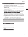
IPv4 Address
Obtain IP address via DHCP :
Status:
‘Allocated’ shows that the IP address is obtained from the DHCP.

19
EN
IP address, Subnet mask, Gateway:
Displays the current IP address which is obtained from the DHCP
Use the following IP address:
Select the choice box if you want to assign the IP address manually.
IPv6 Address
Mark ENABLE check box to use IPv6 address and click SAVE button, then new IPv6 address
will be obtained.
DNS
Obtain DNS address via DHCP :
Obtains the DNS address automatically assigned by DHCP server.
Use the following DNS address :
Requires manual input as per below.
• DOMAIN NAME : Enter the domain for the host name
• PRIMARY DNS SERVER : Enter the IP address of the primary DNS server.
• SECONDARY DNS SERVER : Enter the IP address of the secondary DNS server.

20
Further information
-
site at www.eneo-security.com to receive the latest functionality for your product.
The manual, and other software tools are available on the eneo website at
www.eneo-security.com or on the included CD.
Information on compatible video management software solutions can be found in the
category Videomanagement at www.eneo-security.com.
Open Source Software
The software included in this product contains copyrighted software that is licensed
under open source licenses.
You may obtain the complete corresponding source code from eneo for a period of three
years after the last shipment of this product by sending email to:
If you want to obtain the complete corresponding source code with a physical medium
such as CD-ROM, the cost of physically performing source distribution might be charged.
For more details about Open Source Software, refer to the eneo website at
www.eneo-security.com or an included product CD.
La pagina si sta caricando...
La pagina si sta caricando...
La pagina si sta caricando...
La pagina si sta caricando...
La pagina si sta caricando...
La pagina si sta caricando...
La pagina si sta caricando...
La pagina si sta caricando...
La pagina si sta caricando...
La pagina si sta caricando...
La pagina si sta caricando...
La pagina si sta caricando...
La pagina si sta caricando...
La pagina si sta caricando...
La pagina si sta caricando...
La pagina si sta caricando...
La pagina si sta caricando...
La pagina si sta caricando...
La pagina si sta caricando...
La pagina si sta caricando...
La pagina si sta caricando...
La pagina si sta caricando...
La pagina si sta caricando...
La pagina si sta caricando...
La pagina si sta caricando...
La pagina si sta caricando...
La pagina si sta caricando...
La pagina si sta caricando...
La pagina si sta caricando...
La pagina si sta caricando...
La pagina si sta caricando...
La pagina si sta caricando...
La pagina si sta caricando...
La pagina si sta caricando...
La pagina si sta caricando...
La pagina si sta caricando...
La pagina si sta caricando...
La pagina si sta caricando...
La pagina si sta caricando...
La pagina si sta caricando...
La pagina si sta caricando...
La pagina si sta caricando...
La pagina si sta caricando...
La pagina si sta caricando...
La pagina si sta caricando...
La pagina si sta caricando...
La pagina si sta caricando...
La pagina si sta caricando...
La pagina si sta caricando...
La pagina si sta caricando...
La pagina si sta caricando...
La pagina si sta caricando...
La pagina si sta caricando...
La pagina si sta caricando...
La pagina si sta caricando...
La pagina si sta caricando...
La pagina si sta caricando...
La pagina si sta caricando...
La pagina si sta caricando...
La pagina si sta caricando...
La pagina si sta caricando...
La pagina si sta caricando...
La pagina si sta caricando...
La pagina si sta caricando...
-
 1
1
-
 2
2
-
 3
3
-
 4
4
-
 5
5
-
 6
6
-
 7
7
-
 8
8
-
 9
9
-
 10
10
-
 11
11
-
 12
12
-
 13
13
-
 14
14
-
 15
15
-
 16
16
-
 17
17
-
 18
18
-
 19
19
-
 20
20
-
 21
21
-
 22
22
-
 23
23
-
 24
24
-
 25
25
-
 26
26
-
 27
27
-
 28
28
-
 29
29
-
 30
30
-
 31
31
-
 32
32
-
 33
33
-
 34
34
-
 35
35
-
 36
36
-
 37
37
-
 38
38
-
 39
39
-
 40
40
-
 41
41
-
 42
42
-
 43
43
-
 44
44
-
 45
45
-
 46
46
-
 47
47
-
 48
48
-
 49
49
-
 50
50
-
 51
51
-
 52
52
-
 53
53
-
 54
54
-
 55
55
-
 56
56
-
 57
57
-
 58
58
-
 59
59
-
 60
60
-
 61
61
-
 62
62
-
 63
63
-
 64
64
-
 65
65
-
 66
66
-
 67
67
-
 68
68
-
 69
69
-
 70
70
-
 71
71
-
 72
72
-
 73
73
-
 74
74
-
 75
75
-
 76
76
-
 77
77
-
 78
78
-
 79
79
-
 80
80
-
 81
81
-
 82
82
-
 83
83
-
 84
84


Eneo IED-62F0036P0A Quick Installation Manual
- Categoria
- Telecamere di sicurezza
- Tipo
- Quick Installation Manual
- Questo manuale è adatto anche per
in altre lingue
- English: Eneo IED-62F0036P0A
- français: Eneo IED-62F0036P0A
- Deutsch: Eneo IED-62F0036P0A
Documenti correlati
-
Eneo IPD-73M2812MWA Quick Installation Manual
-
-
-
-
Eneo IEB-63M2812M0A Quick Installation Manual
-
-
-
-
Eneo MPD-62V2812P0A Quick Installation Manual
-