
1st WATCH
WIRELESS RADAR
DRS4W
OPERATOR'S MANUAL
www.furuno.com
Model
PRODUCT NAME: RADAR SENSOR


i
IMPORTANT NOTICES
General
• This manual has been authored with simplified grammar, to meet the needs of international users.
• The operator of this equipment must read and follow the instructions in this manual.
Wrong operation or maintenance can void the warranty or cause injury.
• Do not copy any part of this manual without written permission from FURUNO.
• If this manual is lost or worn, contact your dealer about replacement.
• The contents of this manual and the equipment specifications can change without notice.
• The example screens (or illustrations) shown in this manual can be different from the screens you
see on your display. The screens you see depend on your system configuration and equipment
settings.
• Save this manual for future reference.
• Any modification of the equipment (including software) by persons not authorized by FURUNO will
void the warranty.
• The following concern acts as our importer in Europe, as defined in DECISION No 768/2008/EC.
- Name: FURUNO EUROPE B.V.
- Address: Ridderhaven 19B, 2984 BT Ridderkerk, The Netherlands
• The following concern acts as our importer in UK, as defined in SI 2016/1025 as amended SI 2019/
470.
- Name: FURUNO (UK) LTD.
- Address: West Building Penner Road Havant Hampshire PO9 1QY, U.K.
Trademark Notices
• All brand, product names, trademarks, registered trademarks, and service marks belong to their
respective holders.
• Apple, iPad and iPhone are registered trademarks of Apple, Inc.
• App Store is a registered service mark of Apple, Inc.
• iOS is a registered trademark of Cisco Systems, Inc.
How to discard this product
Discard this product according to local regulations for the disposal of industrial waste. For disposal in
the USA, see the homepage of the Electronics Industries Alliance (http://www.eiae.org/) for the
correct method of disposal.
How to discard a used battery
Some FURUNO products have a battery(ies). To see if your product has a battery, see the chapter
on Maintenance. If a battery is used, tape the + and - terminals of the battery before disposal to pre-
vent fire, heat generation caused by short circuit.
In the European Union
The crossed-out trash can symbol indicates that all types of batteries
must not be discarded in standard trash, or at a trash site. Take the
used batteries to a battery collection site according to your national
legislation and the Batteries Directive 2006/66/EU.
In the USA
The Mobius loop symbol (three chasing arrows) indicates that
Ni-Cd and lead-acid rechargeable batteries must be recycled.
Take the used batteries to a battery collection site according to
local laws.
In the other countries
There are no international standards for the battery recycle symbol. The number of symbols can in-
crease when the other countries make their own recycle symbols in the future.
Cd
Ni-Cd Pb

ii
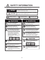
SAFETY INFORMATION
Read these safety instructions before installing or operating the equipment.
WARNING
Indicates a potentially hazardous situation which, if not avoided,
can result in minor or moderate injury.
Warning, Caution
Prohibitive Action
CAUTION
Mandatory Action
Indicates a potentially hazardous situation which, if not avoided,
can result in serious injury or death.
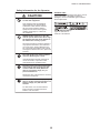
Safety Information for the Operator Safety Information for the Installer
Wear a safety belt and hard hat when
working on the antenna unit.
Serious injury or death can result if
someone falls from the radar mast.
Do not open the equipment.
The installation does not require you
to open the radar sensor.
Be sure the power source is compatible
with the voltage rating of the equipment.
Connection of an incorrect power source
can cause fire or damage the equipment.
Turn off the power at the power source
before beginning the installation.
Fire, electrical shock or serious injury can
result if the power is left on or is applied
while the equipment is being installed.
WARNING
WARNING
ELECTRICAL SHOCK HAZARD
Do not open the equipment.
There are no user servicable parts inside.
The radar antenna emits electromag-
netic radio frequency (RF) energy
which can be harmful, particularly to
your eyes. Never look directly into the
antenna aperture from a close distance
while the radar is in operation or
expose yourself to the transmitting
antenna at a close distance.
Distances at which RF radiation levels of
100, 50 and 10 W/m
2
exist are given in
the table below.
100 W/m
2
10 W/m
2
N/A 0.0 m
Do not disassemble or modify the
equipment.
Fire, electrical shock or serious injury can
result.
Wear a safety belt and hard hat when
working on the antenna unit.
Serious injury or death can result if
someone falls from the radar mast.
CAUTION
Observe the following compass safe
distance to prevent interference to a
magnetic compass.
It is recommended that you connect
the sensor to a disconnecting device
(circuit breaker, etc.) to control the
power.
Standard
compass
1.45 m 0.90 m
Steering
compass
50 W/m
2
N/A
Use the proper fuse.
Use of a wrong fuse can damage the
equipment or cause fire.
Do not depend one navigation device
for the navigation of the vessel.
For the safety of vessel and crew, the
navigator must check all aids available to
confirm position.

SAFETY INFORMATION
iii
WARNING LABEL
A warning label is attached to the sensor. Do not
remove the label. If the label is missing or
damaged, contact a FURUNO agent or dealer
about replacement.
CAUTION
Do not use high-pressure cleaners
to clean this equipment.
This equipment has the waterproof
rating outlined in the specifications,
at the back of this manual. However,
the use of high-pressure cleaning
equipment can cause water ingress,
resulting in damage to, or failure of,
the equipment.
NEVER handle, transport, or turn the
radome upside down unless the 4 large
flat washers and bolts at the bottom of
the radome are securely in place.
Since the transceiver inside the radome is
only taped to the bottom, the transceiver
can come loose, causing damage to the
RT unit and W-LAN antenna if the 4 bolts
and large flat washers are not in place and
secured.
The radar picture may not be updated
when the WLAN signal is weak.
If the WLAN signal is weak, discontinue
use of the sensor, to prevent trouble
associated with un-updated picture.
Keep the sensor and iOS terminal away
from products which use the 2.4 GHz
wireless LAN radio band (Bluetooth
devices, microwave range, etc.), to
prevent malfunction.
Discontinue use of the sensor if it receives
microwave interference.
The sensor cannot function properly if
there is trouble (equipment trouble, low
battery voltage, etc.) with the iOS
terminal.
For this reason, it is recommended to
keep more than one iOS terminal on
board in case of trouble.
Name: Warning Label (2)
Type: 03-129-1001-3
Code No: 100-236-743
Safety Information for the Operator

iv
TABLE OF CONTENTS
FOREWORD ....................................................................................................................v
1. OPERATION .............................................................................................................1
1.1 System Overview .......................................................................................................... 1
1.2 How to Start, Stop the System ...................................................................................... 1
1.3 Transmit, Standby ......................................................................................................... 2
1.4 Display Layout...............................................................................................................2
1.5 Touch Screen Operations ............................................................................................. 3
1.6 Picture Menu .................................................................................................................3
1.7 How to Adjust the Brilliance .......................................................................................... 4
1.8 How to Select a Display Range..................................................................................... 4
1.9 How to Set a Guard Alarm Zone ................................................................................... 4
1.10 How to Reduce Rain Clutter.......................................................................................... 5
1.11 How to Measure the Bearing and Range to a Target.................................................... 5
1.12 How to Off Center the Display....................................................................................... 5
1.13 Echo Stretch.................................................................................................................. 6
1.14 Palette ........................................................................................................................... 6
1.15 Echo Color .................................................................................................................... 6
1.16 Picture Format............................................................................................................... 6
1.17 How to Lock the Display (iPhone only) ......................................................................... 6
1.18 How to Take a Screenshot of the Display ..................................................................... 7
1.19 Settings Menu ...............................................................................................................7
2. MAINTENANCE, TROUBLESHOOTING..................................................................8
2.1 Maintenance..................................................................................................................8
2.2 Replacement of Fuse .................................................................................................... 8
2.3 Troubleshooting ............................................................................................................ 9
2.4 Error Messages............................................................................................................. 9
2.5 Replacement of Magnetron........................................................................................... 9
2.6 Self Test ...................................................................................................................... 10
3. INSTALLATION ......................................................................................................11
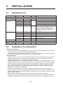
3.1 Equipment List ............................................................................................................ 11
3.2 Installation Considerations .......................................................................................... 11
3.3 How to Install the Radar Sensor ................................................................................. 12
3.4 How to Set up the Radar Sensor ................................................................................ 15
3.4.1 How to start the system ....................................................................................... 15
3.4.2 Heading, timing adjustment ................................................................................. 15
3.4.3 Range unit ........................................................................................................... 17
3.4.4 Tuning initialization .............................................................................................. 17
3.4.5 Sector blank......................................................................................................... 17
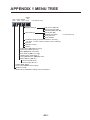
MENU TREE ..............................................................................................................AP-1
RADIO REGULATORY INFORMATION ...................................................................AP-2
SPECIFICATIONS .....................................................................................................SP-1
PACKING LIST ............................................................................................................ A-1
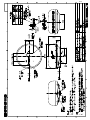
OUTLINE DRAWING ................................................................................................... D-1
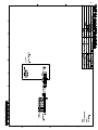
INTERCONNECTION DIAGRAM ................................................................................ S-1

v
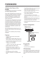
FOREWORD
A Word to the Owner of the
DRS4W
Congratulations on your choice of the FURU-
NO RADAR SENSOR DRS4W.
Since 1948, FURUNO Electric Company has
enjoyed an enviable reputation for innovative
and dependable marine electronics equip-
ment. This dedication to excellence is fur-
thered by our extensive global network of
agents and dealers.
This equipment is designed and constructed
to meet the rigorous demands of the marine
environment. However, no equipment can
perform its intended function unless installed,
operated and maintained properly. Please
carefully read and follow the recommended
procedures for installation, operation, and
maintenance.
We would appreciate hearing from you, the
end-user, about whether we are achieving our
purposes.
Thank you for considering and purchasing
FURUNO.
Features
• Complies with wireless LAN standard
IEEE802.11b.
• Radar sensor forwards radar echoes to an
iPad or iPhone via the 2.4 GHz radio band.
• Compatible with the following iOS terminals
(iOS 6.1.3, 7.0.4 or higher):
• iPhone 5, 5c, 5s, 6 Plus
• iPad 2, 3, 4, Air, Air2, mini, mini2, mini3
• Stylish radome-type radar sensor.
• Echoes shown in green or yellow, or
multicolor in red, yellow or green, corre-
sponding to strong, medium and weak
echoes.
• 14 ranges from 0.125 to 24 NM.
• Brilliance adjustable to suit lighting condi-
tions.
• Two iOS terminals can be connected to the
radar sensor at the same time.
• Guard zone alarm watches for targets en-
tering or exiting an alarm zone.
• Echo stretch lengthens echoes in range
and/or bearing direction.
• Automatic adjustment of sea clutter
(echoes from waves), gain, noise and inter-
ference.
• Off center feature lets you look focus on a
specific area ahead of or around your ves-
sel without losing track of position.
• Self test checks the radar sensor for correct
operation.
System Configuration
Program No.
• 0359329-01.**
** denotes minor modifications.
CE declaration
With regards to CE declarations, please refer
to our website (www.furuno.com), for further
information about RoHS conformity declara-
tions.
RADAR SENSOR
DRS4W
Power supply
12/24 VDC
Wireless LAN (WLAN)
2.4 GHz
AC/DC
Adapter
iOS Terminal
(iPad, iPhone)

1
1. OPERATION
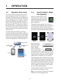
1.1 System Overview
The radar sensor transmits pulses of micro-
wave energy that bounce off any object in
their path. The object returns a tiny part of the
wave's energy to the radar sensor. Radar de-
termines the distance to a target by calculat-
ing the time difference between the trans-
mission of a radar signal and the reception of
the reflected echo. The bearing to a target
found by the radar is determined by the direc-
tion in which the antenna is pointing when it
emits an electronic pulse and then receives a
returning echo.
The radar sensor forwards the returning
echoes to the iOS terminal (iPhone, iPad), us-
ing its wireless LAN module. The radar appli-
cation in the iOS terminal displays the radar
echoes on the terminal’s display and provides
controls for adjustment of the radar picture.
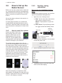
1.2 How to Start, Stop
the System
Power the radar sensor to acti-
vate the system. Open your iPad
or iPhone terminal and click the
[Marine Radar] application icon
(see right figure).
The splash screen appears for a few mo-
ments, then the application tries to connect to
the radar sensor, which normally takes no
more than three seconds. If the connection is
successful, the [Preheating] display appears.
If the connection
failed, the window
shown right ap-
pears. Tap the
[Search again] but-
ton to try to connect
to the radar sensor. If you cannot connect to
the radar sensor, check for interfering objects
near the sensor and make sure the wireless
LAN function is enabled on your terminal.
The preheating stage, which warms the mag-
netron (the device responsible for transmitting
radar pulses), takes approx. 90 seconds. The
time remaining until the completion of the pre-
heating is counted down at the center of the
screen. After the completion of the preheat-
ing, the STBY display appears.
To deactivate the system, disconnect the ra-
dar sensor from the power source.
Note: To connect an iOS terminal to another
DRS4W, reset the application first.
Radar sensor
iPhone
iPad
Wireless LAN
2.4 GHz
Wireless LAN
2.4 GHz
Splash
screen
Searching
radar sensor
Preheating
display
Radar sensor
communciation error!
E0002: Wi-fi communication error
with radar sensor occurred.
Search again

1. OPERATION
2
1.3 Transmit, Standby
Tap the [STBY-TX]
icon at the top right
corner on the screen
to put the radar in
standby, transmit
state alternately.
When you don’t need the radar, set it to stand-
by to extend the life of the magnetron.
Note: The radar application is set to standby
one minute after you switch to another appli-
cation.
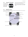
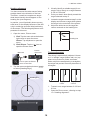
1.4 Display Layout
The figure below shows all the indications, markers and icons that appear on the iPad radar dis-
play. The layout on the iPhone is similar.
STBY-TX icon
Menu tab*
Fixed range rings
Display range
Heading line
Range selection buttons
Cursor
Own ship mark
Bearing, range box
Bearing scale
Bearing line
* Not provided on iPhone.

1. OPERATION
3
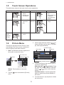
1.5 Touch Screen Operations
The table below shows all the basic touch screen operations.
1.6 Picture Menu
This sensor has three menus: Picture, Color,
and Settings.The Picture menu contains the
most frequently used radar functions.
1. iPad: Tap the Menu tab at the right side of
the screen to show the menu.
iPhone: Tap anywhere to show the
menu.
2. Tap the ( ) icon to activate the [Picture]
menu.
3. Use the page selection buttons ( ) to
browse the items of the menu. For exam-
ple, select [Sector Blank].
4. The [Picture] menu has several types of
controls for adjustment.
Slider bar with and buttons: Drag
the slider bar to adjust the item selected.
Use the or button to fine tune the
setting.
Function buttons: Tap the appropriate
button to select the function labeled on
the button.
5. To close the menu, tap anywhere outside
the menu area.
Operation Action Operation Action
Tap • Open, close
menus.
• Operate vari-
ous buttons.
Drag • Move the cur-
sor.
• Move slider bar
in menus.
• Off center the
display.
Double
tap
• Cancel off
center dis-
play.
Pinch in,
Pinch out
• Select display
range.
Long
push
(approx.
2 sec.)
• Display the
cursor.
Color menu icon
Picture menu icon
Settings menu icon
Menu tab
/
Slider bar
Item name
Page selection buttons
Item no./Item total
Function button
3 / 3

1. OPERATION
4
1.7 How to Adjust the
Brilliance
The brilliance can be adjusted to suit lighting
conditions. Open the menu then tap the ( )
icon. Drag the slider bar to adjust the bril-
liance.
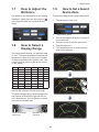
1.8 How to Select a
Display Range
The range selects how far you want the radar
to “see”. The range selected automatically de-
termines the range ring interval, the number
of range rings and pulse repetition rate. The
current range is shown at the top left corner
on the screen.
R: Display range, FRR: Fixed range ring
interval, NR: Number of fixed range rings
To select a display range, tap the range selec-
tion buttons at the bottom right and left cor-
ners. Alternatively, you can pinch in or pinch
out within the display area.
1.9 How to Set a Guard
Alarm Zone
Follow below steps to set a guard alarm zone.
1. Tap the picture menu icon.
2. Tap [Resize] menu.
3. Four circles appear at the four corners of
the guard zone.
4. Drag the circles to set the guard zone.
5. Tap [Active] menu.
6. The dotted lines turn to solid lines and
guard zone appears.
R 0.125 0.25 0.5 0.75 1
FRR 0.0625 0.125 0.125 0.25 0.25
NR 2 2 4 3 4
R1.5 2 3 46
FRR 0.5 0.5 1 1 2
NR 3 4 3 4 3
R 8 12 16 24
FRR 2 3 4 6
NR 4 4 4 4
Decrease the range
(zoom in)
Increase the range
(zoom out)

1. OPERATION
5
Guard Zone Mode
[In]: When the targets enter a target alarm
zone, the alarm occurs.
[Out]: When the targets exit a target alarm
zone, the alarm occurs.
1.10 How to Reduce
Rain Clutter
The antenna picks up rain
clutter (rain, snow, or hail)
in the same manner as
normal targets, as in the
right figure. When rain
clutter masks targets, use
the [Rain] control to re-
duce the clutter. The higher the setting the
greater the reduction of rain clutter
To adjust the rain clutter, open the menu then
tap the ( ) icon. Select the [Rain] screen.
Tap the [Manual] or [Auto] button. For manual
adjustment, drag the slider bar to reduce the
rain clutter.
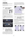
1.11 How to Measure
the Bearing and
Range to a Target
The bearing and range from own ship to a tar-
get can be measured with the cursor. Long
push the screen to show the cursor, which is
a cross (+). Drag the cursor to put it on the
center of the target. See the bearing and
range to the target in the [Bearing/Range]
box, which is to the side of the cursor. After
several seconds, the cursor is erased from
the screen.
Note: A slight difference exists between fin-
ger position and cursor position in order to
see the cursor while dragging it.
1.12 How to Off Center
the Display
Own ship position, or sweep origin, can be
displaced manually or automatically to ex-
pand the view without switching to a longer
range. The maximum amount of shift is 75%
of the range in use.
To off center the display, drag the own ship
mark to the position you want to make the
screen center. To return to the normal display,
double tap the display area.
Manual adjustment
Automatic adjustment
1 / 3
1 / 3
Bearing,
range to
cursor
Cursor
Normal display Off centered display

1. OPERATION
6
1.13 Echo Stretch
On long ranges, target echoes tend to shrink,
making them difficult to see. To enhance tar-
get video on long ranges, use the echo stretch
feature to lengthen echoes in the bearing
and/or range direction.
Open the menu then tap the ( ) icon. Select
the [Echo Stretch] screen. Select [Low] to
lengthen echoes in the bearing direction;
[High] to lengthen echoes in both the bearing
and range directions.
1.14 Palette
The palette feature changes the color of the
background, characters, range rings and
heading line to suit the time of day, daytime or
nighttime.
Open the menu then tap the ( ) icon. Select
[Day] or [Night] as appropriate.
1.15 Echo Color
Echoes can be shown in yellow, green, or
multicolor. Multicolor paints each radar echo
in a color according to its strength, in red, yel-
low or green, corresponding to strong, medi-
um and weak echoes. Open the menu then
tap the ( ) icon. Select the color desired at
[Echo Color].
1.16 Picture Format
You can show the radar picture in landscape
or portrait format. Rotate your terminal to
change the format.*
* Only Portrait display is available on iPhone.
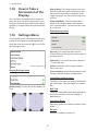
1.17 How to Lock the
Display (iPhone
only)
Tap the screen of iPhone. Tap the key icon of
menu tab to lock the display. Tap the key icon
of menu tab again to unlock.
Note: The display lock is activated only when
the radar application is shown on the top of
iPhone or iPad. The display lock is deactivat-
ed when an alarm occurs.
Item
Color
Day Night
Background White Black
Characters Gray Red
Rings Gray Red
Heading line Gray Red
Echo
Brg dir.
Brg dir.
Rng
dir.
Echo stretch
OFF
Echo stretch
Low
Echo stretch
High
2 / 3

1. OPERATION
7
1.18 How to Take a
Screenshot of the
Display
You can take a screenshot of the radar dis-
play, and save it to the Photos folder in your
terminal. Push the Home and Power buttons
together. You should hear the camera shutter
sound.
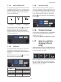
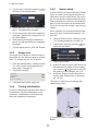
1.19 Settings Menu
The [Settings] menu contains items that once
preset do not require frequent adjustment.
Open the menu then tap the ( ) icon to open
the [Settings] menu.
Display Settings menu
[Full Screen]: Turn the full screen display on
or off.
[Range Ring]: The range rings are the con-
centric circles about own ship position, and
they function to provide an estimate of the
range to a target. You can turn the rings on or
off here.
[Own Ship Mark]: The own ship mark is
shown at the display center and indicates
your current position. You can turn the mark
on or off here.
Initial Settings menu
[Sound]: Turn on/off the alarm sound.*
* When iPhone or iPad is set on mute, there is
no alarm sound.
[Vibration]: Turn on/off the alarm vibration.*
* For iPhone only.
[Units]: Select the unit of range measure-
ment, nm or km.
[Tune Initialize]: Automatically tune the radar
receiver. See the chapter on installation.
Installation Settings menu
The items in this menu are mainly intended for
the serviceman. See the chapter on installa-
tion.
Self Test
Tests the radar sensor and radar application
for proper operation. See the chapter on
Maintenance.
Operation Guide
Operator’s guide to the basic functions of this
radar.
Version
Shows the software version no.
(Version no. appears here)
Full screen ONFull screen OFF
Units
Tune Initialize
nm
>
Sound
Vibration

8
2. MAINTENANCE,
TROUBLESHOOTING
2.1 Maintenance
Regular maintenance is important for good
performance. Check the points mentioned be-
low every 3 to 6 months to keep the radar sen-
sor in good working order. Observe the safety
instructions at the front of this manual when
working on the mast.
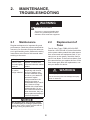
2.2 Replacement of
Fuse
The 5A fuse (Type: FGBO 250V 5A PBF,
Code No.: 000-155-840-10) in the fuse holder
on the power cable protects the radar sensor
from overcurrent and equipment fault. If you
cannot turn on the power, check the fuse to
see if it has blown. If the fuse has blown, find
the reason before you replace the fuse. If the
fuse blows again after the replacement, con-
tact your dealer for advice.
WARNING
DO NOT OPEN THE SENSOR.
Electrical shock hazard
There are no user-serviceable parts
inside. Only qualified personnel are
allowed to work inside the equipment.
Check point Action
Check fixing
bolts for corro-
sion and if tightly
fastened.
Tighten loosened bolts.
Replace corroded bolts.
Coat new bolts with marine
sealant.
Check radome
for cracks,
foreign material.
If a crack is found, repair it
temporarily with a small
amount of sealing com-
pound or adhesive. Bring
the unit to your dealer for
permanent repairs.
Foreign material on the
radome can cause a
considerable drop in sensi-
tivity. Remove foreign
material with a freshwater-
moistened cloth. Do not
use commercial cleaners to
clean the sensor; they can
remove paint and markings
or deform the plastic.
Do not apply paint, anti-corrosive sealant
or contact spray to coating or plastic parts.
Those items contain organic solvents that can
damage coating and plastic parts.
NOTICE
WARNING
Use the proper fuse.
Use of the wrong fuse can damage the equip-
ment or cause fire.

2. MAINTENANCE, TROUBLESHOOTING
9
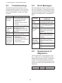
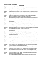
2.3 Troubleshooting
The table below provides simple trouble-
shooting procedures that the user can follow
to restore normal operation. If you cannot re-
store normal operation, contact your dealer
for advice.
2.4 Error Messages
Error messages are shown to alert you to ra-
dar sensor problems. The table below shows
the error messages and accompanying mes-
sage numbers and check points. These alerts
appear in the background; no notification is
given.
2.5 Replacement of
Magnetron
The life expectancy of the magnetron is ap-
prox. 5,000 hours. The effectiveness of the
magnetron decreases over time, causing low-
er-than-normal signal strength and loss of
echoes. If you feel the signal strength is low,
contact your dealer about replacement of the
magnetron.
Trouble Remedy
The power
cannot be
turned on.
• Check if the power cable is
connected to the power
source and the power
source is on.
• Check the power cable for
damage.
• Check if the fuse has blown.
The power is
on but noth-
ing appears
on the
display.
Try adjusting the brightness
with [Brightness] in the
[Settings] menu in your termi-
nal, or [Brilliance] in the radar
application.
The display
freezes.
• Restart the application.
• Reset your terminal.
You cannot
connect to
the wireless
LAN but you
can see the
host on the
terminal.
• Switch between standby
and transmit.
• Restart the application.
• Check the WLAN settings in
your terminal.
• Restart your terminal.
Message
Message no. and
check point
"No radar
sensor
found!"
E0001: Please check Wi-Fi
connection setup and if pow-
er is applied to radar sensor.
"Radar sen-
sor communi-
cation error!"
E0002: Wi-Fi communication
error with radar sensor oc-
curred.
"Radar sen-
sor signal
error!"
E0003: Heading pulse from
radar sensor is not detected.
Please check radar sensor
condition.
E0004: Video signal from ra-
dar sensor is not detected.
Please check radar sensor
condition.
“Guard zone
area is out of
the current
range scale!”
E0005: Please adjust the
range scale or move the
guard zone closer to your lo-
cation.
“Target
Alarm!”
Target(s) entered the guard
zone.
Target(s) exited the guard
zone.
Name Type Code no.
Magnetron E3571 000-126-646

2. MAINTENANCE, TROUBLESHOOTING
10
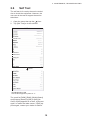
2.6 Self Test
The self test is for use by the service techni-
cian to check the equipment. However, the
user can do the test to support the service
technician.
1. Open the menu then tap the ( ) icon.
2. Tap [Self Test] to do the self test.
The result for [ROM], [RAM], [WLAN Status]
and [Antenna Status] is [OK] or [NG] (No
Good). If [NG] appears for an item, try the test
again, or restart the radar sensor. If [NG] ap-
pears again, contact your dealer for advice.
WLAN=Wireless LAN
Actual value appears in place of “x”.
WLAN FW version
WLAN Status
WLAN Channel
WLAN Power
15dBm
03593929-xx.xx
03593930-xx.xx
0359313-xxxxxxx-xx
172.31.x.xx
172.31.x.xx
xx-xx-xx-xx-xx-xx
x
Scroll

11
3. INSTALLATION
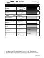
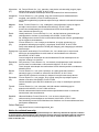
3.1 Equipment List
3.2 Installation Considerations
Name Type Code No. Qty Remarks
Standard supply
Radar Sensor RSB-126-103 - 1
Installation
Materials
CP03-35800 000-024-974 Select
one
Power cable assy., 10 m
CP03-35810 000-024-975 Power cable assy., 15 m
CP03-35820 000-024-976 Power cable assy., 20 m
CP03-35830 000-024-977 Power cable assy., 30 m
CP03-35701 001-265-920 1 - Hex bolt*(M10u25), 4 pcs.
- Flat washer (M10 SUS304), 4 pcs.
- Spring washer (M10 SUS304), 4 pcs.
*For use if thickness of platform is
6–10 mm.
Documents OME-36360 - 1 Operator’s Manual
MDC-36360 - 1 C-ROHS list
E32-01314 - 1 Template
E32-01401 - 1 SSID, password information
E32-01405 - 1 Notes on usage
Spare Parts SP03-17801 001-265-910 1 5A fuse, 2 pcs.
Optional supply
Radome Mount OP03-209 001-078-350 1 Mast mounting bracket for sailboat
General considerations:
• Do not apply paint, anti-corrosive sealant or contact spray to coating or plastic parts. Those items
contain solvents that can damage coating and plastic parts.
• The radar sensor has no power switch. Therefore, it is recommended that you connect the sensor
to a disconnecting device (circuit breaker, etc.) to control the power.
Sensor placement:
• The radar sensor uses the 2.4 GHz wireless LAN radio band to forward radar echoes to the iOS
terminal. Separate the sensor well away from products which also use this band (microwave
range, Bluetooth devices, etc.) to prevent mutual interference.
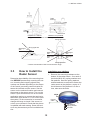
• Install the radar sensor on the hardtop, radar arch or on a mast on an appropriate platform. (For
sailboats, a “radome mount” is optionally available for fixing the sensor to a mast.) Place the sen-
sor where there is a good all-round view with, as far as possible, no part of the ship’s superstruc-
ture or rigging intercepting the scanning beam. Any obstruction will cause shadow and blind
sectors. Be sure there are no metallic objects near the antenna. See the next page for typical
placement on a sailboat and powerboat.
• Observe the wireless LAN communication range noted in the illustration on the next page.
• In order to reduce the chance of picking up electrical interference, avoid where possible routing
the power cable near other electrical equipment onboard. Also, avoid running the cable in parallel
with other power cables.
• Select a location that does not allow water to accumulate at the base of the sensor.
• A magnetic compass will be affected if the radar sensor is too close to the compass. Observe the
compass safe distances mentioned on page ii to prevent interference to a magnetic compass.

3. INSTALLATION
12
3.3 How to Install the
Radar Sensor
Determine the suitability of the mounting loca-
tion BEFORE permanently mounting the sen-
sor. Incoming and outgoing signals may
overlap one another depending on the shape
of the vessel, preventing communication be-
tween the terminal and the sensor. Set the
sensor on the selected location and connect
the sensor to the power source. Turn on the
sensor. Open the terminal, turn on the radar
application and try to connect the terminal to
the sensor (see section 3.4.1 for how to start
the system). If the connection is successful,
change the range to check if the sensor re-
ceives your command. Check that the picture
is updated with each sweep. Some trial and
error may be necessary to find a suitable loca-
tion.
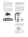
Installation on a platform
1. Remove the mounting hardware at the
bottom of the radar sensor - four each of
hex bolts (M10u20), spring washers and
flat washers. Save the spring washers
and flat washers to use them to fasten the
radar sensor to the platform, at step 4. If
the thickness of the platform is 5 mm or
less, also save the bolts.
Radar
sensor
Radar
sensor
Installation on a sailboat
Radar
sensor
Radar sensor
Installation on a powerboat
45°
60°
Weak signal
area
30°
30°
Location and wireless LAN communication range
Typical installation on a sailboat, power boat
Strong signal area
Strong signal area
Weak signal
area
Strong signal area
Weak signal
area
Weak signal
area
Weak signal
area
Hex bolt
Spring washer
Flat washer
STERN
BOW
Power
cable

3. INSTALLATION
13
2. Construct a platform (steel or aluminum)
referring to the outline drawing and the
mounting template. Fasten the platform to
the mounting location. The holes in the
platform must be parallel with the fore and
aft line.
3. Put the radar sensor on the platform with
the bow mark (U) on sensor aligned with
the bow.
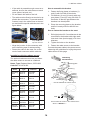
4. Use hex bolts*, flat washers and spring
washers (removed at step 1) to fasten the
radar sensor to the platform. The torque
for the bolts must be 19.6 to 24.5 N•m.
*See the figure below to determine bolt
length to use.
Note: NEVER handle, transport, or turn
the radome upside down unless the
4 large flat washers and bolts at the
bottom of the radome are securely in
place.
Since the transceiver inside the radome is
only taped to the bottom, the transceiver
can come loose, causing damage to the
RT unit and W-LAN antenna if the 4 bolts
and large flat washers are not in place
and secured. For this reason, NEVER
handle, transport, or turn the radome up-
side down unless the 4 bolts and large flat
washers are secured.
5. Connect the supplied power cable to the
sensor. Observe the guidelines for laying
the power cable shown on this page.
6. Connect the power cable to the power
source.
Guidelines for laying the power cable
• The connectors must not strike any part of
the vessel by wind, etc.
• The load applied to the connectors must
not be more than its own weight.
Flat
washer
Sensor base assy.
Platform
Hex bolt
(See below.)
Apply marine
sealant.
L
Spring
washer
Platform thickness and bolt to use
Platform
thickness
Bolt to use
5 mm or less
M10×20 (Supplied, prefastened to radome.)
6 - 10 mm
M10×25 (Supplied.)
Over 10 mm
Use bolt where the length of “L” above is
15 mm. Supply locally.
Large flat washer
Small flat
washer
Spring washer
Default position of bolt and washer
Screw
hole
1: Red
2: Braid
3: Blue
Power cable
pin assignment
La pagina si sta caricando...
La pagina si sta caricando...
La pagina si sta caricando...
La pagina si sta caricando...
La pagina si sta caricando...
La pagina si sta caricando...
La pagina si sta caricando...
La pagina si sta caricando...
La pagina si sta caricando...
La pagina si sta caricando...
La pagina si sta caricando...
La pagina si sta caricando...
La pagina si sta caricando...
La pagina si sta caricando...
La pagina si sta caricando...
La pagina si sta caricando...
La pagina si sta caricando...
La pagina si sta caricando...
La pagina si sta caricando...
La pagina si sta caricando...
-
 1
1
-
 2
2
-
 3
3
-
 4
4
-
 5
5
-
 6
6
-
 7
7
-
 8
8
-
 9
9
-
 10
10
-
 11
11
-
 12
12
-
 13
13
-
 14
14
-
 15
15
-
 16
16
-
 17
17
-
 18
18
-
 19
19
-
 20
20
-
 21
21
-
 22
22
-
 23
23
-
 24
24
-
 25
25
-
 26
26
-
 27
27
-
 28
28
-
 29
29
-
 30
30
-
 31
31
-
 32
32
-
 33
33
-
 34
34
-
 35
35
-
 36
36
-
 37
37
-
 38
38
-
 39
39
-
 40
40


in altre lingue
- English: Furuno DRS4W User manual
Documenti correlati
-
Furuno DRS4DNXT Guida d'installazione
-
-
-
-
-
-
-
-
-
Altri documenti
-
Garmin GMR Fantom™ 18 Guida d'installazione
-
 YOTA Ruby Manuale utente
-
PETKIT SUS304 Manuale utente
-
Crosby WNI10TC WNITC Compression Load Cells Manuale utente
-
AMS Asset Monitor Guida d'installazione
-
 AmazonBasics B07WJWRY82 Manuale utente
-
 AmazonBasics B07WMRJ68R Manuale utente
-
 AmazonBasics B07WMRJ15D Manuale utente


