
GP-39
OPERATOR'S MANUAL
www.furuno.com
GPS Navigator
Model
(w/GPA-C01)

7KHSDSHUXVHGLQWKLVPDQXDO
LVHOHPHQWDOFKORULQHIUHH
࣭)85812$XWKRUL]HG'LVWULEXWRU'HDOHU
$VKLKDUDFKR
1LVKLQRPL\D-$3$1
$ 6(3
3ULQWHGLQ-DSDQ
$OOULJKWVUHVHUYHG
$ $35
3XE1R 20($
7$68 *3*3$&

i
IMPORTANT NOTICE
General
• This manual has been authored with simplified grammar, to meet the needs of international us-
ers.
• The operator of this equipment must read and follow the descriptions in this manual. Wrong op-
eration or maintenance can cancel the warranty or cause injury.
• Do not copy any part of this manual without written permission from FURUNO.
• If this manual is lost or worn, contact your dealer about replacement.
• The contents of this manual and equipment specifications can change without notice.
• The example screens (or illustrations) shown in this manual can be different from the screens
you see on your display. The screens you see depend on your system configuration and equip-
ment settings.
• Save this manual for future reference.
• Any modification of the equipment (including software) by persons not authorized by FURUNO
will cancel the warranty.
•
The following concern acts as our importer in Europe, as defined in DECISION No 768/2008/EC.
- Name: FURUNO EUROPE B.V.
- Address: Ridderhaven 19B, 2984 BT Ridderkerk, The Netherlands
• All brand and product names are trademarks, registered trademarks or service marks of their
respective holders.
How to discard this product
Discard this product according to local regulations for the disposal of industrial waste. For disposal
in the USA, see the homepage of the Electronics Industries Alliance (http://www.eiae.org/) for the
correct method of disposal.
How to discard a used battery
Some FURUNO products have a battery(ies). To see if your product has a battery(ies), see the
chapter on Maintenance. Follow the instructions below if a battery(ies) is used. Tape the + and -
terminals of battery before dispossal to prevent fire, heat generation caused by short circuit.
In the European Union
The crossed-out trash can symbol indicates that all types of batteries
must not be discarded in standard trash, or at a trash site. Take the
used batteries to a battery collection site according to your national leg-
islation and the Batteries Directive 2006/66/EU.
In the USA
The Mobius loop symbol (three chasing arrows) indicates that Ni-Cd
and lead-acid rechargeable batteries must be recycled. Take the used
batteries to a battery collection site according to local laws.
In the other countries
There are no international standards for the battery recycle symbol. The number of symbols can
increase when the other countries make their own recycle symbols in the future.
Cd
Ni-Cd Pb

ii
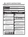
SAFETY INSTRUCTIONS
Be sure that the power supply is
compatible with the voltage rating
of the equipment.
Connection of an incorrect power
supply can cause fire or equipment
damage. The voltage rating of the
equipment appears on the label
above the power connector.
The glass of an LCD panel breaks
easily. Handle the LCD carefully.
Injury can result if the glass breaks.
No single navigation aid (including
this unit) should ever be relied upon
as the exclusive means for navigat-
ing your vessel.
The navigator is responsible for check-
ing all aids available to confirm his
position. Electronic aids are intended
to assist, not replace, the navigator.
The operator and installer must read the applicable safety instructions before attempting to operate
or install the equipment.
Indicates a potentially hazardous situation which, if not avoided,
could result in death or serious injury.
WARNING
Indicates a potentially hazardous situation which, if not avoided,
can result in minor or moderate injury.
CAUTION
Warning, Caution
Prohibitive Action
Mandatory Action
CAUTION
WARNING
WARNING
Do not disassemble or modify the
equipment.
Fire, electrical shock or serious injury
can occur.
Do not install the equipment where it
may get wet from rain or water splash.
Water in the equipment can result in fire,
electrical shock or damage to the
equipment.
Ground the equipment to prevent
electrical shock and mutual
interference.
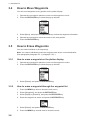
Observe the following safe compass
distances to prevent interference to a
magnetic compass:
Standard
compass
Steering
compass
0.45 m 0.30 m
GP-39
0.30 m 0.30 m
GPA-C01
Turn off the power at the mains
switchboard before beginning the
installation.
Fire, electrical shock or serious injury
can result if the power is left on or is
applied while the equipment is being
installed.
Turn off the power immediately if
water leaks into the equipment or the
equipment is emitting smoke or fire.
Continued use of the equipment can
cause fire or electrical shock.
Do not use high-pressure cleaners to
clean this equipment.
This equipment has the waterproof
rating outlined in the specifications, at
the back of this manual. However, the
use of high-pressure cleaning equipment
can cause water ingress, resulting in
damage to, or failure of, the equipment.

iii
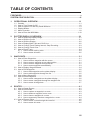
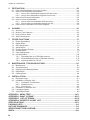
TABLE OF CONTENTS
FOREWORD.................................................................................................................... v
SYSTEM CONFIGURATION ......................................................................................... vLi
1. OPERATIONAL OVERVIEW.................................................................................1-1
1.1 Controls ......................................................................................................................1-1
1.2 How to Turn Power On/Off .........................................................................................1-2
1.3 How to Adjust LCD and Key Panel Brilliance .............................................................1-3
1.4 Display Modes............................................................................................................1-3
1.5 Menu Overview...........................................................................................................1-8
1.6 How to Enter the MOB Mark.....................................................................................1-10
2. PLOTTER DISPLAY OVERVIEW..........................................................................2-1
2.1 How to Select the Display Range...............................................................................2-1
2.2 How to Shift the Cursor ..............................................................................................2-1
2.3 How to Shift the Display .............................................................................................2-2
2.4 How to Display/Hide Track and COG Line .................................................................2-2
2.5 How to Change Track Plotting Interval, Stop Recording ............................................2-3
2.6 How to Change Track Color .......................................................................................2-4
2.7 How to Erase Track....................................................................................................2-4
2.7.1 How to erase track by color............................................................................2-4
2.7.2 How to erase all tracks ...................................................................................2-5
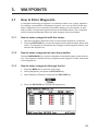
3. WAYPOINTS..........................................................................................................3-1
3.1 How to Enter Waypoints.............................................................................................3-1
3.1.1 How to enter a waypoint with the cursor ........................................................3-1
3.1.2 How to enter a waypoint at own ship position ................................................3-1
3.1.3 How to enter a waypoint through the list ........................................................3-1
3.1.4 How to enter waypoints automatically ............................................................3-3
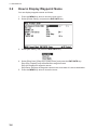
3.2 How to Display Waypoint Name.................................................................................3-4
3.3 How to Edit Waypoints ...............................................................................................3-5
3.3.1 How to edit waypoints on the plotter display ..................................................3-5
3.3.2 How to edit waypoints through the list............................................................3-5
3.4 How to Move Waypoints.............................................................................................3-6
3.5 How to Erase Waypoints ............................................................................................3-6
3.5.1 How to erase a waypoint on the plotter display..............................................3-6
3.5.2 How to erase a waypoint through the waypoint list ........................................3-6
3.5.3 How to erase all waypoints.............................................................................3-7
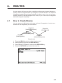
4. ROUTES ................................................................................................................4-1
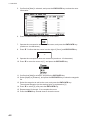
4.1 How to Create Routes ................................................................................................4-1
4.2 How to Edit Routes.....................................................................................................4-3
4.2.1 How to replace a waypoint in a route .............................................................4-3
4.2.2 How to delete a waypoint from a route...........................................................4-3
4.2.3 How to insert a waypoint in a route ................................................................4-4
4.2.4 How to temporarily deselect a waypoint in a route.........................................4-4
4.3 How to Erase a Route ................................................................................................4-5
4.3.1 How to erase a route through the route list ....................................................4-5
4.3.2 How to erase all routes...................................................................................4-5

TABLE OF CONTENTS
iv
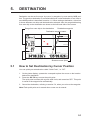
5. DESTINATION .......................................................................................................5-1
5.1 How to Set Destination by Cursor Position ................................................................5-1
5.2 How to Set Destination by Waypoint..........................................................................5-2
5.2.1 How to set a destination waypoint with the cursor ......................................... 5-2
5.2.2 How to set a destination waypoint from the list..............................................5-2
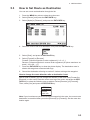
5.3 How to Set Route as Destination ............................................................................... 5-3
5.4 How to Cancel a Destination......................................................................................5-4
5.4.1 How to cancel a destination with the cursor...................................................5-4
5.4.2 How to cancel a destination through the list...................................................5-4
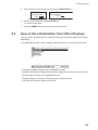
5.5 How to Set a Destination from Other Displays........................................................... 5-5
6. ALARMS ................................................................................................................6-1
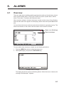
6.1 Overview ....................................................................................................................6-1
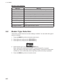
6.2 Buzzer Type Selection ............................................................................................... 6-2
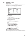
6.3 How to Set an Alarm ..................................................................................................6-3
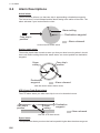
6.4 Alarm Descriptions.....................................................................................................6-4
7. OTHER FUNCTIONS .............................................................................................7-1
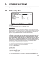
7.1 Plotter Setup Menu ....................................................................................................7-1
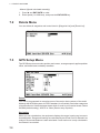
7.2 Delete Menu...............................................................................................................7-2
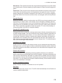
7.3 GPS Setup Menu .......................................................................................................7-2
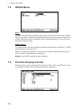
7.4 WAAS Menu...............................................................................................................7-4
7.5 Position Display Format .............................................................................................7-4
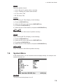
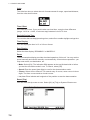
7.6 System Menu .............................................................................................................7-5
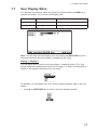
7.7 User Display Menu.....................................................................................................7-7
7.8 I/O Setup Menu........................................................................................................ 7-10
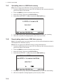
7.8.1 Uploading data to a USB flash memory.......................................................7-12
7.8.2 Downloading data from a USB flash memory .............................................. 7-12
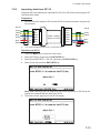
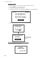
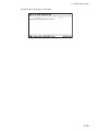
7.8.3 Importing data from GP-32...........................................................................7-13
8. MAINTENANCE, TROUBLESHOOTING...............................................................8-1
8.1 Maintenance...............................................................................................................8-1
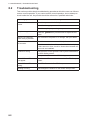
8.2 Troubleshooting .........................................................................................................8-2
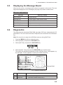
8.3 Displaying the Message Board ..................................................................................8-3
8.4 Diagnostics.................................................................................................................8-3
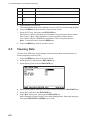
8.5 Clearing Data .............................................................................................................8-4
9. INSTALLATION .....................................................................................................9-1
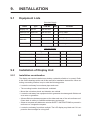
9.1 Equipment Lists..........................................................................................................9-1
9.2 Installation of Display Unit..........................................................................................9-1
9.2.1 Installation consideration................................................................................9-1
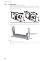
9.2.2 Desktop mount...............................................................................................9-2
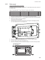
9.2.3 Flush mount ...................................................................................................9-3
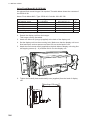
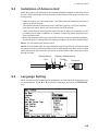
9.3 Installation of Antenna Unit ........................................................................................9-5
9.4 Language Setting.......................................................................................................9-5
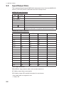
9.5 Input/Output Data.......................................................................................................9-6
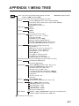
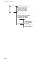
APPENDIX 1 MENU TREE .......................................................................................AP-1
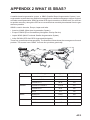
APPENDIX 2 WHAT IS SBAS? ................................................................................AP-3
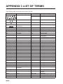
APPENDIX 3 LIST OF TERMS .................................................................................AP-4
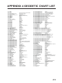
APPENDIX 4 GEODETIC CHART LIST ...................................................................AP-5
SPECIFICATIONS .....................................................................................................SP-1
PACKING LISTS.......................................................................................................... A-1
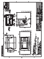
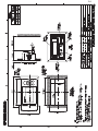
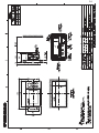
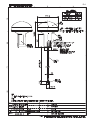
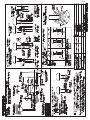
OUTLINE DRAWINGS................................................................................................. D-1
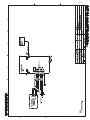
INTERCONNECTION DIAGRAM ................................................................................ S-1
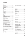
INDEX..........................................................................................................................IN-1

v
FOREWORD
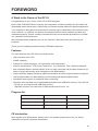
A Word to the Owner of the GP-39
Congratulations on your choice of the GP-39 GPS Navigator.
Since 1948, FURUNO Electric Company has enjoyed an enviable reputation for innovative and
dependable marine electronics is furthered by our extensive global network of agents and dealers.
Your navigator is designed and constructed to meet the rigorous demands of the marine environ-
ment. However, no machine can perform its intended function unless installed, operated and
maintained properly. Please carefully read and follow the recommended procedures for installa-
tion, operation and maintenance.
We would appreciate feedback from you, the end-user, about where we are achieving our
purposes.
Thank you for considering and purchasing FURUNO equipment.
Features
The main features of the GP-39 are as shown below.
• High-resolution color LCD
• WAAS capability
• Storage for 10,000 waypoints, 100 routes and 3,000 track points
• Alarms: Arrival/Anchor, XTE (Cross-Track Error), Trip, Odometer, Time, WAAS and Speed
• Man overboard feature records position at time of man overboard and provides continuous up-
dates of range and bearing when navigating to the MOB position.
• Unique Highway display provides a graphic presentation of boat’s progress toward a waypoint.
• User-programmable nav data displays provide analog and digital navigation data.
• Navigation data output to the autopilot when connecting.
• Waypoint and route data can be uploaded/downloaded via a USB flash memory* to the GP-39.
* Do not use a write-protected USB flash memory.
USB flash memory is a trade mark of USB Implementers Forum, Inc.
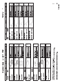
Program No.
**: Minor change
CE declaration
With regards to CE declarations, please refer to our website (www.furuno.com), for further
information on RoHS conformity declarations.
Name No. Ver.
CPU MAIN 2051584-01.** December, 2015
CPU Boot 2051583-**.** December, 2015
GPS 4850465014 December, 2015

FOREWORD
vi
Open source software
This product includes software to be licensed under the GNU General Public License (GPLv2),
MIT and others. The program(s) is/are free software(s), and you can copy it and/or redistribute it
and/or modify it under the terms of the GPLv2 as published by the Free Software Foundation.
Please access to the following URL if you need source codes: https://www.furuno.co.jp/cgi/
cnt_oss_e01.cgi.

vii
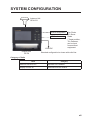
SYSTEM CONFIGURATION
Category of Units
Units Category
Antenna Unit GPA-C01 Exposed to the weather.
Display Unit GP-39 Protected from the weather.
External Equipment*
Display Unit
GP-39
Antenna Unit
GPA-C01
12-24VDC
Standard configuration is shown with solid line.
Fish Finder
PPI Sonar
Radar
GP-39
MENU
ENT
CNTR
DISP GOTO
MARK
MOB
B
R
I
L
L
USB flash memory
* Target position,
TLL sentence,
can be input
from external
equipment.

SYSTEM CONFIGURATION
viii
This page is intentionally left blank.

1-1
1. OPERATIONAL OVERVIEW
1.1 Controls
Key Description
(Cursorpad)
- Shifts the cursor.
- Selects item on menus.
- Opens the Menu. (For plotter and highway displays, press twice,
For other displays, press once)
- Shows the zoom window (plotter and highway displays only).
- Long press: Returns own ship position to center (plotter display only).
- Momentary press: Confirms selection on menus.
Selects display mode.
Sets destination.
- Long press: Inscribes MOB mark.
- Momentary press: Registers own ship position as waypoint.
- Long press: Turns power off.
- Momentary press: Turns power on./Shows Brill window.
GP-39
MENU
ENT
CNTR
DISP
GO TO
MARK
MOB
B
R
I
L
L

1. OPERATIONAL OVERVIEW
1-2
How to detach the hard cover from the unit
Put your thumbs on the front of the cover and forefingers at its back edge, and pull it
toward you.
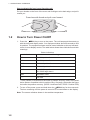
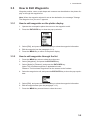
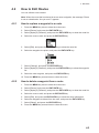
1.2 How to Turn Power On/Off
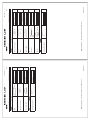
1. Press the /BRILL key to turn on the power. The unit beeps and then starts up
with the last-used display mode. Your equipment takes about 90 seconds to find
its position. The equipment shows receiver status indication at the top left-hand
corner in most display modes. The table below shows these indications and their
meanings.
Status indications
*: DOP (Dilution of Precision) is the index of position accuracy, and it is the distri-
bution pattern of satellites used in position fixing. Generally, the smaller the figure
the better the position accuracy. (HDOP: Horizontal DOP, PDOP: Position DOP)
2. To turn off the power, press and hold down the /BRILL key for three seconds.
The time remaining until the power is turned off is counted down on the display.
Note: The screen refreshes slower in low ambient temperature.
Indication Meaning
2D 2D GPS position fixed
3D 3D GPS position fixed
W2D 2D WAAS position fixed
W3D 3D WAAS position fixed
DOP* 2D: HDOP larger than 4
3D: PDOP larger than 6
SIM Simulation mode
- - - Not fixed
Press here with thumb and pull cover forward.

1. OPERATIONAL OVERVIEW
1-3
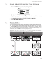
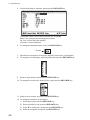
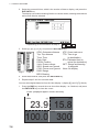
1.3 How to Adjust LCD and Key Panel Brilliance
1. Press the /BRILL key to show the following window.
2. To adjust the LCD brilliance, press /BRILL key.
The setting changes “0o1o…o7o6…0o1…” continuously. Maximum setting
is 7. You can use also the cursorpad (W, X) to adjust the brilliance.
3. To adjust the panel brilliance, press the cursorpad (S, T, max: 7).
4. Press ENT/CNTR or MENU key.
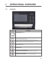
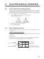
1.4 Display Modes
Your unit has seven display modes: Plotter Display, Highway Display, Steering Dis-
play, Nav Data Display, Satellite Monitor Display and User Display 1 and User Display
2. Press the DISP key to select a display mode. Each time the key is pressed, the dis-
play mode changes in the sequence shown below. To step through the displays in re-
verse order, press the DISP key more than three seconds.
Note: When input data for SOG, RNG, XTE, TTG and ETA exceeds the displayable
range, the indications change as shown in the following table.
SOG: *99 when over 999. RNG: *999 when over 999.
XTE: *9.99 when over 99.99. TTG: *9H*9M when over 99H59M.
ETA date and time: ** **.**.** when TTG is over 99H59M.
[1]: Plotter display
20.0
350
[2]: Highway display
299
166
0.46
14.6
N
E
[3]: Steering display
14.6
300
0.46 299
00 15
[4]: Nav Data display
14.6
300
135 21.074
34 44.589
N
E
[5]: Satellite Monitor display[6]: User display 1
40.0
N
E
[7]: User display 2
40.0
1.60
12.0
133
32
30
28
25
22
17
15
13
11
08
05
02
05
02
25
05
02
32
30
17
13
22
08
11
DISP DISP
DISP
DISP
DISPDISP
DISP

1. OPERATIONAL OVERVIEW
1-4
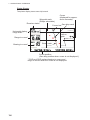
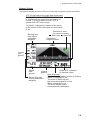
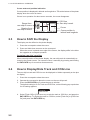
Plotter Display
The plotter display traces own ship’s track.
Receiver status
Waypoint mark
(Shape selectable)
Horizontal display
range scale
Bearing to cursor*
Range to cursor*
*:COG and SOG replace bearing to cursor and
range to cursor when the cursor is not displayed.
Cursor position
(Own ship position when cursor is not displayed.)
Own ship mark
Course bar
Cursor
(displayed for approx.
seven seconds)
92
N 34 08.375
N 34 08.250
E 135 09.750E 135 09.500
Lat/Lon
grids
Boat’s track

1. OPERATIONAL OVERVIEW
1-5
Highway Display
The highway display provides a 3D view of own ship’s progress toward destination.
Bearing from
own ship to
destination
waypoint
Speed
over
ground
Course
over
ground
Digital XTE indication
(in nautical miles)
Range from own
ship to destination
waypoint
Own ship mark
The boat mark displays course as follows:
When no waypoint is set;
The mode is North-up and
the arrow shows boat’s course.
When a waypoint is set;
The arrow shows boat’s
course towards destination.
Direction to steer
(to return to course)
Current
position
299
166
0.46
14.6
N
E
Destination
waypoint name
XTE (Cross-track error) scale and arrow mark
Arrow shifts with boat’s XTE. When the arrow
is aligned with the center line the boat is on
course. The arrow blinks if boat’s XTE is
greater than XTE scale range.
“N (North)” is displayed, instead of the arrow,
at the center of the scale when no destination
is set.
: Steer right.
: Steer left.

1. OPERATIONAL OVERVIEW
1-6
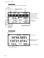
Steering Display
The steering display provides steering information.
Nav Data Display
14.6
300
0.46 299
00 15
Time-To-Go
to destination
Time
Receiver status
Speed
over ground
Bearing reference;
MAG(netic) or TRUE
Range from
own ship to
destination
Own ship mark
Bearing scale
Estimated Time of
Arrival at destination
Bearing to
the destination
Course over ground
Bearing destination
12/11/09
17:57:40
Speed over ground
14.6
300
135 21.074
34 44.589
N
E
Receiver status
Date and time
Position in latitude
and longitude
Course over ground

1. OPERATIONAL OVERVIEW
1-7
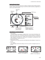
Satellite Monitor Display
The satellite monitor display shows the condition of GPS and GEO (WAAS) satellites.
Number, bearing and elevation angle of all GPS and GEO satellites (if applicable) in
view of your receiver appear.
User Display 1 and User Display 2
• Digital display
The digital display shows digital navigation data. You can select what data to dis-
play in one to four cells. The choices of data are odometer distance, trip distance,
time, date, position, power source voltage, speed over ground, course over ground,
range, bearing, cross-track-error, time-to-go to a destination, estimated time of ar-
rival at destination, waypoint and none.
• Speedometer display
The speedometer display provides both digital and analog displays of speed over
ground.
• COG display
The COG display shows both analog course over ground, and digital speed over
ground.
Receiver
signal level
Bars show
signal level.
DOP value
Elevation
45
Elevation 5
Altitude
Satellite numbers in
reverse video are
used for positioning.
Receiver
status
1.60
12.0
133
32
30
28
25
22
17
15
13
11
08
05
02
05
02
25
05
02
32
30
17
13
22
08
11
GEO satellite
Area not used
for positioning
(set at menu)
Digital display (four cells) Speedometer display COG display
40.0
N
E
40.0
23.9
15.8
55.7
335
(default: User display 1)
(default: User display 2)

1. OPERATIONAL OVERVIEW
1-8
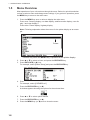
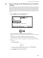
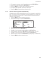
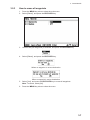
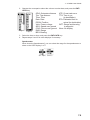
1.5 Menu Overview
Most operations of your unit are done through the menu. Below is a quick introduction
on how to select a menu and change menu settings. If you get lost in operation, press
the MENU key to return to the main menu.
1. Press the MENU key once or twice to display the main menu.
Press once: Steering display, nav data display, satellite monitor display, user dis-
play 1 and user display 2.
Press twice: Plotter display, highway display.
Note: Following explanation takes the menus for the plotter display as an exam-
ple.
2. Press S or T to select an item, and press the ENT/CNTR key.
3. Press ENT/CNTR (or X) key.
For example, select [Plotter Setup] and press the ENT/CNTR key.
4. Press S or T to select option desired.
For example, select [COG/BRG ref.]
5. Press the ENT/CNTR key (or X).
A window appears showing the options for the selected item.
6. Press S or T to select option desired.
7. Press the ENT/CNTR key (or X).
8. Press the MENU key (or W) twice to close the menu.
*
Cursor
*: Shown only when the MENU key is pressed at the plotter display.

1. OPERATIONAL OVERVIEW
1-9
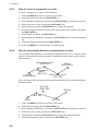
How to enter alphanumeric data
Some menu operations require you to enter alphanumeric data (A to Z, 0 to 9) and
symbols (&, _, #,’ , -, > and space). The procedure which follows shows how to enter
alphanumeric data. For example, to change the waypoint name “WP0006” to “KOBE”,
do as follows:
1) Press S or T to select “K”.
2) Press X, and press S or T to select “O”.
3) Press X, and press S or T to select “B”.
4) Press X, and press S or T to select “E”.
5) Press X, and press S or T to select “ “(space).
6) Press X, and press S or T to select “ ” (space).
7) Press the ENT/CNTR key.
Cursor

1. OPERATIONAL OVERVIEW
1-10
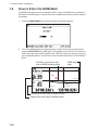
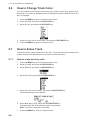
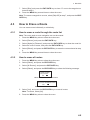
1.6 How to Enter the MOB Mark
The MOB mark denotes man overboard position. Only one MOB mark is displayed.
Each time the MOB mark is entered the previous MOB mark and its position data are
overwritten.
1. Press the MARK/MOB key until the following message appears.
2. To set the MOB position as the destination, confirm that [Yes] is selected and
press the ENT/CNTR key. MOB mark (“M”) appears and a blue line is drawn be-
tween own ship mark and the MOB mark. This line shows the shortest course to
go to the MOB position, and arrows on the line show the direction to the MOB po-
sition.
Range from own ship to MOB position
Bearing from own ship to MOB position
MOB mark
(red)
Shortest course from own
ship to MOB position (blue)
N 34 08.500
N 34 08.375
E 135 10.000E 135 09.750
95
0.20
La pagina sta caricando ...
La pagina sta caricando ...
La pagina sta caricando ...
La pagina sta caricando ...
La pagina sta caricando ...
La pagina sta caricando ...
La pagina sta caricando ...
La pagina sta caricando ...
La pagina sta caricando ...
La pagina sta caricando ...
La pagina sta caricando ...
La pagina sta caricando ...
La pagina sta caricando ...
La pagina sta caricando ...
La pagina sta caricando ...
La pagina sta caricando ...
La pagina sta caricando ...
La pagina sta caricando ...
La pagina sta caricando ...
La pagina sta caricando ...
La pagina sta caricando ...
La pagina sta caricando ...
La pagina sta caricando ...
La pagina sta caricando ...
La pagina sta caricando ...
La pagina sta caricando ...
La pagina sta caricando ...
La pagina sta caricando ...
La pagina sta caricando ...
La pagina sta caricando ...
La pagina sta caricando ...
La pagina sta caricando ...
La pagina sta caricando ...
La pagina sta caricando ...
La pagina sta caricando ...
La pagina sta caricando ...
La pagina sta caricando ...
La pagina sta caricando ...
La pagina sta caricando ...
La pagina sta caricando ...
La pagina sta caricando ...
La pagina sta caricando ...
La pagina sta caricando ...
La pagina sta caricando ...
La pagina sta caricando ...
La pagina sta caricando ...
La pagina sta caricando ...
La pagina sta caricando ...
La pagina sta caricando ...
La pagina sta caricando ...
La pagina sta caricando ...
La pagina sta caricando ...
La pagina sta caricando ...
La pagina sta caricando ...
La pagina sta caricando ...
La pagina sta caricando ...
La pagina sta caricando ...
La pagina sta caricando ...
La pagina sta caricando ...
La pagina sta caricando ...
La pagina sta caricando ...
La pagina sta caricando ...
La pagina sta caricando ...
La pagina sta caricando ...
La pagina sta caricando ...
La pagina sta caricando ...
La pagina sta caricando ...
La pagina sta caricando ...
La pagina sta caricando ...
La pagina sta caricando ...
La pagina sta caricando ...
La pagina sta caricando ...
La pagina sta caricando ...
La pagina sta caricando ...
La pagina sta caricando ...
La pagina sta caricando ...
La pagina sta caricando ...
La pagina sta caricando ...
La pagina sta caricando ...
La pagina sta caricando ...
-
 1
1
-
 2
2
-
 3
3
-
 4
4
-
 5
5
-
 6
6
-
 7
7
-
 8
8
-
 9
9
-
 10
10
-
 11
11
-
 12
12
-
 13
13
-
 14
14
-
 15
15
-
 16
16
-
 17
17
-
 18
18
-
 19
19
-
 20
20
-
 21
21
-
 22
22
-
 23
23
-
 24
24
-
 25
25
-
 26
26
-
 27
27
-
 28
28
-
 29
29
-
 30
30
-
 31
31
-
 32
32
-
 33
33
-
 34
34
-
 35
35
-
 36
36
-
 37
37
-
 38
38
-
 39
39
-
 40
40
-
 41
41
-
 42
42
-
 43
43
-
 44
44
-
 45
45
-
 46
46
-
 47
47
-
 48
48
-
 49
49
-
 50
50
-
 51
51
-
 52
52
-
 53
53
-
 54
54
-
 55
55
-
 56
56
-
 57
57
-
 58
58
-
 59
59
-
 60
60
-
 61
61
-
 62
62
-
 63
63
-
 64
64
-
 65
65
-
 66
66
-
 67
67
-
 68
68
-
 69
69
-
 70
70
-
 71
71
-
 72
72
-
 73
73
-
 74
74
-
 75
75
-
 76
76
-
 77
77
-
 78
78
-
 79
79
-
 80
80
-
 81
81
-
 82
82
-
 83
83
-
 84
84
-
 85
85
-
 86
86
-
 87
87
-
 88
88
-
 89
89
-
 90
90
-
 91
91
-
 92
92
-
 93
93
-
 94
94
-
 95
95
-
 96
96
-
 97
97
-
 98
98
-
 99
99
-
 100
100


in altre lingue
- English: Furuno GP39 User manual
Documenti correlati
Altri documenti
-
Boston Whaler 150 Montauk Manuale del proprietario
-
-
Si-tex Nautilus NT & Neptune NT Manuale utente
-
Raymarine Loran/GPS 6400 Manuale utente
-
Garmin 618 Manuale utente
-
 Geonav 4C User and Installation Manual
-
Garmin GPS152H Manuale utente
-
Seiko 8X22 Guida utente
-
Magellan SPORTRAK COLOR User Manual Addendum
-
Simrad RS35 VHF and HS35 Handset Istruzioni per l'uso
