MULTIPLEX Acro Master Building Instructions
- Categoria
- Giocattoli
- Tipo
- Building Instructions

1
F
GB
D
E
I
Bauanleitung 3 ... 8
Notice de construction 9 ... 14
Building instructions 15 ... 28
Instruzioni di montaggio 29 ... 34
Instrucciones de montaje 35 ... 34
Baukasten / kit # 21 4215
© Copyright by MULTIPLEX 2006
Ersatzteile
/ /
/ /
/ Replacement parts 24

3
D
F
GB
I
E
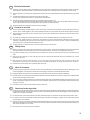
Sicherheitshinweise
-
Prüfen Sie vor jedem Start den festen Sitz des Motors und der Luftschraube - insbesondere nach dem Transport, härteren Landungen
sowie Abstürzen. Prüfen Sie ebenfalls vor jedem Start den festen Sitz und die richtige Position der Tragflächen auf dem Rumpf.
- Akku erst einstecken, wenn Ihr Sender eingeschaltet ist und Sie sicher sind, daß das Bedienelement für die Motorsteuerung auf "AUS"
steht.
- Im startbereiten Zustand nicht in den Bereich der Luftschraube greifen.
Vorsicht in der Luftschraubendrehebene - auch Zuschauer zur Seite bitten!
- Zwischen den Flügen die Motortemperatur durch vorsichtige Fingerprobe prüfen und
vor einem Neustart den Motor ausreichend abkühlen lassen. Die Temperatur ist richtig, wenn Sie den Motor problemlos berühren
können. Insbesondere bei hohen Außentemperaturen kann dieses bis zu 15 Minuten dauern.
- Denken Sie immer daran: Niemals auf Personen und Tiere zufliegen.
Conseils de sécurité
-
Avant chaque décollage, vérifiez la fixation du moteur et de l'hélice, notamment après le transport, après les atterrissages violents et
après un “Crash”. Vérifiez également, avant chaque décollage la fixation ainsi que le positionnement de l’aile par rapport au fuselage.
- Ne branchez l’accu de propulsion que si vous êtes sûr que votre émetteur est allumé et que l’élément de commande moteur est en
position “ARRET”.
- Ne mettez pas vos doigts dans l’hélice! Attention à la mise en marche, demandez également aux spectateurs de reculer.
- Entre deux vols, vérifiez en posant un doigt dessus, la température du moteur, laissezle refroidir suffisamment avant le prochain
décollage. La température est correcte si vous pouvez maintenir votre doigt ou votre main sur le moteur. Le temps de refroidissement
peut varier jusqu’à 15 minutes s’il fait particulièrement chaud.
- Pensez-y toujours: ne volez jamais vers ou au-dessus des personnes ou des animaux.
Safety notes
- Before every flight check that the motor and propeller are in place and secure - especially after transporting the model, and after hard
landings and crashes. Check also that the wing is correctly located and firmly secured on the fuselage before each flight.
- Don’t plug in the battery until you have switched on the transmitter, and you are sure that the motor control on the transmitter is set to
“OFF”.
- When the model is switched on, ready to fly, take care not to touch the propeller. Keep well clear of the propeller disc too, and ask
spectators to stay back.
- Allow the motor to cool down after each flight. You can check this by carefully touching the motor case with your finger. The
temperature is correct when you can hold your finger on the case without any problem. On hot days this may take up to 15 minutes.
- Please keep in mind at all times: don’t fly towards people or animals.
Note di sicurezza
- Prima di ogni decollo controllare che il motore e la eliche siano fissati stabilmente - specialmente dopo il trasporto, atterraggi duri e se il
modello è precipitato. Controllare prima del decollo anche il fissaggio e la posizione corretta delle ali sulla fusoliera.
- Collegare la batteria solo quando la radio è inserita ed il comando del motore è sicuramente in posizione ”SPENTO”.
- Prima del decollo non avvicinarsi al campo di rotazione della eliche. Attenzione alla eliche in movimento - pregare che eventuali spettatori
si portino alla dovuta distanza di sicurezza!
- Tra un volo e l’altro controllare cautamente con le dita la temperatura del motore e farli raffreddare sufficientemente prima di ogni nuovo
decollo. La temperatura è giusta se si possono toccare senza problemi. Specialmente con una temperatura esterna alta questo può
durare fino a 15 minuti.
- Fare attenzione: Non volare mai nella direzione di persone ed animali.
Advertencias de seguridad
- Compruebe antes de cada despegue que el motor y la hélice estén fuertemente sujetados, sobretodo después de haberlo transportado,
de aterrizajes más fuertes así como después de una caída. Compruebe igualmente antes de cada despegue que las alas estén bien
sujetas y bien colocadas en el fuselaje.
- Conectar la batería, cuando la emisora esté encendida y Usted esté seguro que el elemento de mando para el motor esté en ”OFF”.
- No meter la mano en la zona inmediata a la hélice cuando el avión esté a punto de despegar. ¡Cuidado con la zona de la hélice! ¡Pedir a
los espectadores que se aparten!
- Entre los vuelos hay que comprobar cuidadosamente la temperatura del motor con el dedo y dejar que el motor se enfríe antes de volver
a despegar. La temperatura es correcta, si puede tocar el motor sin problemas. Sobretodo en el caso de temperaturas del ambiente muy
altas, esto puede tardar unos 15 minutos.
- Recuerde: No volar nunca hacía personas o animales.

15
Examine your kit carefully!
MULTIPLEX model kits are subject to constant quality checks throughout the production process, and we hope that you
are satisfied with the contents of your kit. However, we would ask you to check all the parts before you start
construction (using the Parts List as a guide), as we cannot exchange components which you have already
worked on. If you find a part is not acceptable for any reason, please take it back to your supplier (model shop), as he
is your first port of call. After checking, he will send the part or the kit to our Quality Control department. Please be sure
to include the purchase receipt and a brief description of the fault, otherwise we cannot process your complaint.
We are constantly working on improving our models, and for this reason we must reserve the right to change the kit
contents in terms of shape or dimensions of parts, technology, materials and fittings, without prior notification. Please
understand that we cannot entertain claims against us if the kit contents do not agree in every respect with the
instructions and the illustrations.
Caution!
Radio-controlled models, and especially model aircraft, are by no means playthings. Building and operating
them safely requires a certain level of technical competence and manual skill, together with discipline and a
responsible attitude at the flying field. Errors and carelessness in building and flying the model can result in
serious personal injury and damage to property. Since we, as manufacturers, have no control over the
construction, maintenance and operation of our products, we are obliged to take this opportunity to point out
these hazards and to emphasise your personal responsibility.
Additional items required:
e.g. MULTIPLEX Micro IPD receiver 35 MHz A-band Order No. 5 5971
alternatively: 40 MHz Order No. 5 5972
MULTIPLEX RX-7 Synth DS IPD receiver 35 MHz A-band Order No. 5 5885
MULTIPLEX Nano S servo (2 required for ailerons) Order No. 6 5120
Tiny-S (2 required for rudder and elevator) Order No. 6 5121
Servo extension lead (2 required for aileron servos) Order No. 8 5031
”AcroMaster” power set, HiMax HC 3516-1130 Order No. 33 2631
Contents: 1 HC 3516-1130 motor
1 11 x 5.5” APC propeller
1 5 mm Ø collet propeller driver
1 speed controller, e.g. Castle Creations Phoenix 45A
Flight battery:
MULTIPLEX flight battery, e.g. LiBATT 2100 mAh - 3200 mAh, 3 cells (maximum load approx. 40 A)
Adhesive: cyano-acrylate
Use any type of medium or thick cyano-acrylate adhesive (”cyano”, ”CA”). Do not use styrofoam cyano. Epoxy
adhesives produce what initially appears to be a sound joint, but the bond is only superficial, and the hard resin breaks
away from the parts under load. White glue is entirely unsuitable. However, hot-melt adhesive from a glue gun (”HM”) is
a very useful alternative - especially for mounting servos.
Tools:
Scissors, balsa knife, combination pliers, long-nose pliers, cross-point / slot-head screwdrivers (for servo output arms).
Specification:
Wingspan 1095 mm
Overall fuselage length 1150 mm
All-up weight min. 920 g
Wing area 36.6 dm²
Wing loading (FAI) min. 25 g / dm²
RC functions Aileron, elevator, rudder and throttle
Note: please remove the illustration pages from the centre of the instructions.
# 21 4215
GB

16
Important note
This model is not made of styrofoam™, and it is
not possible to glue the material using white glue
or epoxy. Please be sure to use cyano-acrylate glue
exclusively, preferably in conjunction with cyano
activator (kicker). Use medium or high-viscosity
(thick) cyano (”CA”) for all joints. When gluing
Elapor® parts always spray one face with activator,
and allow it to air-dry until the surface looks ”dry”
(takes about two minutes). Apply cyano glue to the
mating surface, then place the parts together and
immediately position them.
Please be cautious when working with cyano-
acrylate adhesives. These glues can harden in
seconds, so don’t allow them to contact your
fingers or other parts of your body. Always wear
protective goggles to guard against eye injuries.
Keep these materials well out of the reach of
children.
the large control surface travels required for 3-D aerobatics.
However, they are also useful for ”normal” aerobatics, as
the holes are the correct size for the pre-formed snake inner
rods. To fit the servo output arm extensions 43 cut off the
raised collar around the central hole in the original output
arm, and fix the parts together using the standard retaining
screw and the locating screw 49, as shown in Fig. 05. Don’t
over-tighten the screws, or the threads will strip!
Carefully lay the fuselage shells down flat, and connect the
pre-formed end of the steel inner rods (including snake
sleeves) to the servo output arms. For ”normal aerobatics”
use the innermost hole in the output arm extensions, and
for 3-D aerobatics the outermost hole. Apply cyano to the
channels for the snakes. Check once more that the fuselage
shell is exactly flat (straight), then glue the snake sleeve in
the channel. Fig. 06
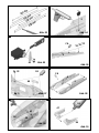
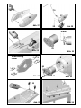
5. Installing the motor mounts
Glue the two motor mounts 60 in the right and left fuselage
shells using cyano. Ensure that the mounts 60 fit flush with
the foam shells before you apply the glue. Fig. 07
6. Canopy latch
Glue the canopy latch clips 32 in the fuselage shells as
shown in Fig. 07.
7. Joining the fuselage shells
Tape the servo leads in the fuselage so that they don’t get
in the way when you join the fuselage shells. Offer up the
fuselage shells 3 + 4 ”dry” (no glue), and check that
everything fits correctly. Apply thick cyano to one shell, hold
the second shell against it, and check that the fuselage is
straight and correctly aligned before the glue sets. This may
take up to a minute, depending on humidity. Hold the
fuselage in your hands for a further two or three minutes,
checking constantly that the fuselage is still straight, because
the adhesive takes at least this length of time to cure. Fig.
08
Place the motor mount brace 62 between the rear ends of
the motor mounts (a pair of pointed-nose pliers is very useful
here) and secure it with cyano. Fig. 09
8. Preparing the tailplane
Glue together the elevator joiner components 46 + 47 on a
flat surface. It is important that the parts are not twisted
relative to each other.
Fig. 10
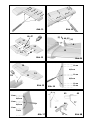
Cut slots for the hinges 42 in the tailplane 12 and the elevator
13 using a sharp balsa knife, positioned as shown in Figs.
11 + 12.
Ensure that the slots are in line with each other, and are
exactly central. Figs. 11 + 12
Install the hinges ”dry” and check that the elevators are
aligned correctly and move freely. Dismantle the parts. Glue
the elevator joiner 46 / 47 between the elevator panels 13.
Push the hinges about ¼ of the way into the elevators, apply
cyano to both sides, then immediately push them into final
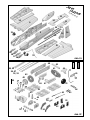
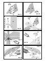
1. Before assembling the model
Please check the contents of your kit.
You will find Figs. 01 + 02 and the Parts List helpful here.
Note: the control ”snakes” are supplied in the following
lengths, and will need to be cut to final length:
2 off 3 / 2 Ø x 480 mm snake outer sleeve
2 off 2 / 1 Ø x 500 mm snake inner tube
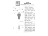
2. Preparing the control snakes
The first step is to cut the snake outers and inners to the
lengths stated below. To cut the sleeves, place them on a
hard surface and roll them to and fro under a sharp balsa
knife, so that they are grooved all round. They can then
simply be broken off.
3 / 2 Ø snake outer sleeves
54 = 480 mm 55 = 400 mm
2 / 1 Ø snake inner tubes
56 = 500 mm 57 = 420 mm
The short pieces of sleeve left over are not required for the
model.
Fig. 03
3. Completing the snakes
Prepare the control snakes by slipping the inner tubes 56 /
57 into the outer sleeves 54 / 55, followed by the steel inner
rods 52 / 53. Parts 54, 56 and 52 are required for the rudder,
and parts 55, 57 and 53 for the elevator.
4. Preparing the fuselage shells
The first step is to install the Tiny-S servos for rudder and
elevator in the fuselage shells 3 + 4. Place the servos in the
recesses and apply a drop of thick cyano or hot-melt glue to
secure them. Fig. 04
The servo output arm extensions 43 are used to produce

25
position. Wipe off excess glue at the pivot line.
Allow the glued hinge joints to set hard, then assemble
the tailplane and elevators again, but pushing the hinges
only ¼ of the way into the tailplane. Apply cyano to both
sides of the hinges as described previously, then push the
elevators into final position. Wipe off excess adhesive
immediately. Fig. 13
Fit the pushrod connector on the elevator horn as shown
in Fig. 14, and lock the nut with a drop of paint or glue.
9. Gluing the tailplane to the fuselage
Offer up the tailplane to the fuselage and check that it is
an accurate fit, and that it can be aligned properly. Glue it
in place using cyano, and align it accurately before the
glue sets hard. Fig. 15
10. Preparing the fin
Cut the slots for the hinges 42 in the tailplane 15 and the
rudder 16 using a sharp balsa knife, as shown in Figs. 16
- 17.
Ensure that the slots are in line with each other, and are
exactly central.
Install the hinges ”dry” and check that the rudder is
aligned correctly and moves freely. Dismantle the parts.
Fit the tailwheel wire 77 through the tailskid bush 45 and
the rudder horn 44, and bend the end at 90° as close to
the horn as possible, as shown in Fig. 18.
Glue the horn 44 to the rudder,
but apply the cyano to the
underside only. Now cut a slot about 1.5 mm deep above
the horn to accept the tailskid wire.
Push the hinges about ¼ of the way into the rudder, apply
cyano to both sides, then immediately push them into final
position. Wipe off excess glue at the pivot line.
Allow the glued hinge joints to set hard, then assemble
the fin, rudder and tailskid wire 77 again, but this time
pushing the hinges and the tailskid bush 45 only ¼ of the
way in again. Apply cyano to both sides of the hinges as
described previously, then push the rudder into final
position. Wipe off excess adhesive immediately. Fig. 19
Swing the tailwheel wire 77 over the rudder horn 44, align
the parts and glue the wire to the slot in the rudder, using
plenty of cyano to obtain a sound joint. Fig. 20
Fit the pushrod connector on the rudder horn as shown in
Fig. 21, and lock the nut with a drop of paint or glue.
Glue in rudder fin Fig.22
The tailwheel 78 can now be fitted to complete this stage:
fit a retaining collar 79 on the wire, followed by the wheel
and the second collar. Apply a drop of cyano to the two
wheel collars 79.
Caution: apply the adhesive on the tip of a small
screwdriver or similar tool. Take care not to glue the
wheel to the axle! Fig. 24
11. Installing the main undercarriage mount
Offer up the undercarriage mount 76 to the recess in the
fuselage. Press it into place ”dry”, so that the locating lugs
push their way into the foam, then simply glue it in place
with cyano. Fig. 24
12. Preparing the wheel spats (replacement part No.
22 4204)
Glue the wheel spat brackets 75 in the outer wheel spat
shells 19 / 20 on both sides. Fit the collet 72 and the 5
mm socket-head grubscrew 74. Close the wheel spats by
gluing the inner spat shells 17 / 18 to the outer shells 19 /
20 using cyano. Figs. 25 - 27
13. Completing and installing the main undercarriage
Fit the inner collets 72 as shown in the picture, and fit the
wheels 71 together with the assembled wheel spats on
the undercarriage unit 70. Align the parts carefully. Fit the
outer collets 72, and tighten the grubscrews to fix the
wheels and spats on the undercarriage.
Fig. 28
Push the undercarriage unit 70 in the undercarriage
mount, make sure it snaps into place, and secure it with a
drop of cyano. Fig. 29
14. Installing the motor
The motor must be attached to the motor bulkhead 61 in
such a way that the end of the shaft is located about 10
mm beyond the front face of the bulkhead. Fig. 30
For most power plants you will need to fit packing behind
the motor to achieve this. The kit contains a spacer ring
63 which is suitable for the recommended Himax motors
(long shaft).
15. Attaching the motor bulkhead to the motor
mounts
The design of the motor mounts 60 and the motor
bulkhead 61 allows you to adjust the sidethrust and
downthrust of the motor. When the four adjustor screws
64 are fitted flush, the mount is already installed
asymmetrically; this arrangement gives maximum
sidethrust and no downthrust. Make the following
adjustments to set the motor thrustline at the correct initial
angle. Note that we are working from the rear of the
bulkhead.
Upper left adjustor screw 0.5 mm = approx. 1
turn
Upper right adjustor screw 1.5 mm = approx. 3
turns
Lower left adjustor screw 0 mm = approx. 0
turns
Lower right adjustor screw 1 mm = approx. 2
turns
Figs. 31 + 32
The correct sidethrust and downthrust are established in
an initial careful test-flying procedure, and when this is
completed you should use a sanding block and new
abrasive paper to sand down the nose of the fuselage to
align it with the spinner, as the final curvature varies
according to the sidethrust and downthrust of the motor.
16. Completing the canopy
Insert the latch tongues 33 in the canopy latch clips, and

26
check that they fit correctly. Place the canopy 5 on the
fuselage and press down lightly to position the latch tongues
correctly. Carefully open the canopy, bend the latch tongues
33 slightly to one side, and apply cyano to the joint surfaces.
Straighten the latch tongues again immediately. Fig. 33
If you wish, you can paint the canopy at this stage. Please
note that you must use our MULTIPrimer, # 60 2700, prior
to painting. Mask off the edge of the canopy using tape.
Apply a very thin coat of the primer; just wipe it on and off
again, as if you were cleaning the surface. After this
treatment you can paint the canopy using any paint of your
choice.
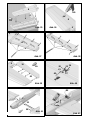
17. Joining the wing shells
Lay the wing panels 6 / 7 (top shells) on a flat building board,
with the rear flat section making contact with the board; allow
the root area to project as shown in the illustration. Weight
down the panels at the centre section and the tip. Carefully
slide the styrofoam strip 22 under the wing leading edge
until the wing shell is fully supported, then fix the strip in that
position. Fig. 34
Apply thick cyano to the wing shells 6 / 7 along all the contact
lines of the internal structure. Don’t apply too much glue in
the areas on both sides of the spar, otherwise the spar may
not fit in its socket. Now apply cyano to the side of the wing
cover panel 8 / 9. Don’t worry about running out of time -
depending on humidity you have one or two minutes before
the glue starts to set. Now insert the wing cover panel and
immediately position if correctly; press it down evenly with
the flat of your hand, working from the aileron area towards
the thickest part of the wing. Leave the wing in this position
(no tests!) for a few minutes, because the glue takes at
least two to five minutes in order to set hard. Fig. 35
18. Installing the servos
The Nano S aileron servos are installed standing upright in
the wings. The servo leads can be drawn through to the
wing root using a length of wire with a hook formed in the
end. You may need to use servo extension leads, # 8 5031.
Place the servos in the recesses in the wing and secure
each with a drop of cyano or hot-melt glue applied to the
mounting lugs. Fig. 36
19. Installing the ailerons
Cut slots in the wing panels 6 / 7 and the ailerons 10 / 11 for
the hinges 42, as shown in Figs. 37 + 38.
Ensure that the slots are in line with each other, and are
exactly central.
Install the hinges ”dry” and check that the ailerons are aligned
correctly and move freely. Remove the ailerons again.
Push the hinges about ¼ of the way into the ailerons, apply
cyano to both sides, then immediately push them into final
position. Wipe off excess glue at the pivot line.
Allow the glued hinge joints to set hard, then assemble the
ailerons and wings again, but pushing the hinges only ¼ of
the way in. Apply cyano to both sides of the hinges as
described previously, then push the ailerons into final
position. Wipe off excess adhesive immediately. Fig. 39
20. Aileron pushrods
Glue the horns 34 in the recesses in the ailerons using cyano.
The aileron linkages are assembled from parts 38,35,34
and 37, as shown in Fig. 40.
Screw the clevis 40 on the threaded end of the pushrod 41
and set it to the correct length. Connect the pushrod using
the pushrod connector, as shown in Fig. 40.
21. Final assembly
The first step in assembling the model is to fit the tubular
spars 50 / 51 in one wing panel. Carefully insert the wing
panel in the recess in the side of the fuselage, at the same
time threading the aileron servo lead into the interior. Fit the
second wing panel on the other side and draw the servo
lead through. Fig. 41
22. Receiving system components
1. Motor: already installed.
2. Speed controller: behind the motor, supported by the
cables.
3. LiPo 2100 - 3200 flight battery: depending on the mode’s
balance, on the angled area behind the motor, or on the
shelf under the canopy and above the wing.
4. Connect the servo / speed controller cables to the receiver
and fit it in the compartment above the fuselage air vents.
Pack foam rubber round it if required.
Velcro (hook-and-loop) tape 30 + 31 is supplied in the kit for
retaining the components mentioned above.
Fig. 42
23. Centre of Gravity
Right from the outset, the RC system components should
be installed with the model’s Centre of Gravity in mind; any
corrections should be made by re-positioning these items.
The CG should be in the range 110 - 120 mm aft of the wing
root leading edge, measured at the fuselage. Fig. 43
24. Initial testing
Install all the airborne components and connect them. Set
up the control surface travels as stated below, and check
the ”sense” (direction) of the servos. All the control surfaces
must move freely. Check that the motor spins in the correct
direction, and reverse it if necessary.
25. Fitting the propeller
Fit the propeller on the motor as shown in Fig. 44. The driver
features an integral holder for the EPP spinner.
26. Basic settings (guideline only!):
Centre of Gravity: 110 - 120 mm
Longitudinal dihedral: 0°
Motor downthrust: 0 - 2°
Motor sidethrust: 2 - 3° (right)
Control surface travels measured at the point of maximum
chord
”normal” 3-D
Ailerons: 35 mm 60 mm
Elevator: 35 mm 70 mm
Rudder: 45 mm 80 mm

27
Dualrate for Elevator and Ailerons 30 -50%
Expo
Ailerons 30%, Elevator 50%
27. Test-flying
Longitudinal dihedral = 0°; this is defined by the model itself.
Centre of Gravity:
Start by setting the CG within the stated range. Now to the
fine-tuning: fly straight and level at half-throttle, then roll
inverted. If you have to apply a lot of ”down” to maintain
level flight, the model is nose-heavy, and you need to move
the CG back. If the machine tends to climb when inverted,
the CG is too far rearward. The CG is correct when you
need to apply just slight down-elevator for inverted level flight.
Correcting the tracking:
First the static balancing: hold the model by the spinner and
rudder; it should balance in the normal flight attitude. If one
wing is heavy (swings down), add ballast to the lighter tip.
During the next flight apply just enough throttle for the model
to remain airborne, and trim it for normal flight. Now fly the
model inverted and check its tracking. Add ballast if
necessary after the model has landed.
Sidethrust:
Place the model in straight and level flight, allow it to fly past
you at full-throttle, then pull up into a vertical climb. In a
vertical climb the model should show no tendency to fall
away to either side. If it veers to the left, add more right
sidethrust, and vice versa. However, please note that any
wind will also tend to push the aeroplane off course.
Downthrust:
Place the model in straight and level flight, and allow it to fly
past you at full-throttle, so that you view the model from the
side. Now pull up into a vertical climb. The model should
continue to climb vertically, with no tendency to tip forward
or over onto its back. If not, adjust the downthrust to correct
the fault.
After making these corrections you may find it necessary to
repeat the procedure for fine-tuning the model’s Centre of
Gravity.
Aileron differential
Fly three of four rolls to the right at half-throttle; if the model
ends up veering off to the right, the differential needs to be
increased. If it veers to the left, the differential is already too
great, and needs to be reduced.
28. Gilding the lily - applying the decals
The kit is supplied with a multi-colour decal sheet. Cut out
the individual name placards and emblems and apply them
to the model in the positions shown in the kit box illustration,
or in an alternative arrangement which you find pleasing.
29. Safety
Safety is the First Commandment when flying any model
aircraft. Third party insurance should be considered a basic
essential. If you join a model club suitable cover will usually
be available through the organisation. It is your personal
responsibility to ensure that your insurance is adequate (i.e.
that its cover includes powered model aircraft).
Make it your job to keep your models and your radio control
system in perfect order at all times. Check the correct
charging procedure for the batteries you are using. Make
use of all sensible safety systems and precautions which
are advised for your system. An excellent source of practical
accessories is the MULTIPLEX main catalogue, as our
products are designed and manufactured exclusively by
practising modellers for other practising modellers.
Always fly with a responsible attitude. You may think that
flying low over other people’s heads is proof of your piloting
skill; others know better: the real expert does not need to
prove himself in such childish ways. Let other pilots know
that this is what you think too. Always fly in such a way that
you do not endanger yourself or others. Bear in mind that
even the best RC system in the world is subject to outside
interference. No matter how many years of accident-free
flying you have under your belt, you have no idea what will
happen in the next minute.
All of us in the MULTIPLEX team hope you have many hours
of pleasure building and flying your new model.
MULTIPLEX Modellsport
Product development and maintenance
Klaus Michler
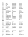
Parts list - AcroMaster kit
Part No. Description Material Dimensions
No. off
1 1 Kit building instructions Paper, 80 g / m² A4
2 1 Decal sheet Printed adhesive film 700 x 1000 mm
3 1 L.H. fuselage shell Moulded Elapor foam Ready made
4 1 R.H. fuselage shell Moulded Elapor foam Ready made
5 1 Canopy Moulded Elapor foam Ready made
6 1 L.H. wing panel Moulded Elapor foam Ready made
7 1 R.H. wing panel Moulded Elapor foam Ready made
8 1 L.H. wing cover panel Moulded Elapor foam Ready made
9 1 R.H. wing cover panel Moulded Elapor foam Ready made
10 1 L.H. aileron Moulded Elapor foam Ready made

28
Part No. Description Material Dimensions
No. off
11 1 R.H. aileron Moulded Elapor foam Ready made
12 1 Tailplane Moulded Elapor foam Ready made
13 1 L.H. elevator Moulded Elapor foam Ready made
14 1 R.H. elevator Moulded Elapor foam Ready made
15 1 Fin Moulded Elapor foam Ready made
16 1 Rudder Moulded Elapor foam Ready made
17 1 L.H. inner wheel spat Moulded EPP foam Ready made
18 1 R.H. inner wheel spat Moulded EPP foam Ready made
19 1 L.H. outer wheel spat Moulded EPP foam Ready made
20 1 R.H. outer wheel spat Moulded EPP foam Ready made
21 1 Spinner Moulded EPP foam Ready made, approx. 62 Ø
22 1 Wing jig strip Pre-cut EPS foam 10 x 30 x 460 mm
Small items set
30 3 Hook-and-loop tape, hook Plastic 25 x 60 mm
31 3 Hook-and-loop tape, loop Plastic 25 x 60 mm
32 2 Canopy-Lock latch clip Inj. moulded plastic Ready made
33 2 Canopy-Lock latch tongue Inj. moulded plastic Ready made
34 2 Acro glue-fitting horn (ailerons) Inj. moulded plastic Ready made
35 4 Pushrod connector Metal Ready made, 6 mm Ø
36 4 Washer Metal M2
37 4 Nut Metal M2
38 4 Socket-head grubscrew Metal M3 x 3 mm
39 1 Allen key Metal 1.5 mm A/F
40 2 Clevis Inj. moulded plastic Ready made
41 2 Pre-formed aileron pushrod Metal M2 x 200 mm
42 3 x 6 Film hinge (sprues of 6) Inj. moulded plastic Ready made
43 2 Servo output arm extension Inj. moulded plastic Ready made
44 1 Glue-fitting horn, rudder / tailskid Inj. moulded plastic Ready made
45 1 Glue-fitting tailwheel bush Inj. moulded plastic Ready made
46 1 Elevator joiner A (with horn) Inj. moulded plastic Ready made
47 1 Elevator joiner B Inj. moulded plastic Ready made
48 1 Spinner holder Inj. moulded plastic Ready made
49 2 Servo output arm extension screw Metal
Wire set
50 1 Front tubular spar GRP tube 10 Ø x 7.4 x 200 mm
51 1 Rear tubular spar CFRP tube 10 Ø x 7.4 x 620 mm
52 1 Pre-formed rudder pushrod Metal 0.8 Ø x 580 mm
53 1 Pre-formed elevator pushrod Metal 0.8 Ø x 510 mm
54 1 Snake outer sleeve, rudder Plastic (480 mm*) 3 Ø x 2 x 480 mm
55 1 Snake outer sleeve, elevator Plastic (480 mm*) 3 Ø x 2 x 400 mm
56 1 Snake inner tube, rudder Plastic (500 mm*) 2 Ø x 1 x 500 mm
57 1 Snake inner tube, elevator Plastic (500 mm*) 2 Ø x 1 x 420 mm
AcroMaster motor mount incl. screws
60 2 Motor mount Inj. moulded plastic Ready made
61 1 Motor bulkhead Inj. moulded plastic Ready made
62 1 Motor mount brace Inj. moulded plastic Ready made
63 1 Spacer ring Inj. moulded plastic Ready made
64 4 Motor bulkhead adjustor screw Metal M3 x 8 mm
65 4 Motor bulkhead mounting screw Metal M3 x 16 mm
Undercarriage set
70 1 Main undercarriage unit Metal 2.5 Ø, ready made
71 2 Lightweight wheel Moulded EPP foam 53 Ø, hub bore 2.5 mm
72 4 Collet Metal 2.7 Ø x 7 x 5 mm
73 2 Socket-head grubscrew Metal M3 x 3 mm
74 2 Socket-head grubscrew Metal M3 x 5 mm
75 2 Wheel spat bracket Inj. moulded plastic Ready made
76 1 Undercarriage mount Plastic Ready made
77 1 Tailwheel wire Metal 1.3 mm Ø
78 1 Lightweight tailwheel Plastic 26 Ø, hub bore 1.5 mm
79 2 Tailwheel retainer (tubular rivet) Metal 2 Ø x 0.2 x 3 mm

17
Abb. 01
Abb. 02
7
6
5
13
12
14
10
8
16
15
11
9
22
50
51
3
4
21
17
20
70
71
18
19
72
73
74
75
76
77
78
79
30 31
32
33
37, 36, 35, 38
44
40
34
41
42
43
45
46
47
48
54, 55
56, 57
52, 53
61
60
63
64
65
62
49
Kit # 21 4215
39

18
Abb. 03
Abb. 05
Abb. 04
Abb. 07 Abb. 08
Abb. 09
480 mm
500 mm
420 mm
400 mm
Abb. 10
Abb. 06
3
HG
43
CA
3
54, 56, 52
CA
32
60
3
CA
4
3
CA
47
46
60
60
62
CA

19
Abb. 17
Abb. 14
Abb. 15
Abb. 16
Abb. 13
Abb. 18
Abb. 12
Abb. 11
12 mm
64,5 mm
12 mm
12 mm
64,5 mm
71 mm
64,5 mm
64,5 mm
12 mm
12 mm
12 mm
15 mm
12 mm
12 mm
12 mm
10 mm
43,5 mm
43,5 mm
12 mm
12 mm
12 mm
11,5 mm
43,5 mm
43,5 mm
13
CA
14
12
42
46, 47
12
37, 36, 46, 35, 38
13
14
12
CA
45
77
44
45
77
ca. 30°
44

20
Abb. 25
Abb. 22
Abb. 23
Abb. 21
Abb. 26
Abb. 20
Abb. 19
Abb. 24
16
15
CA
42
45
44
77
16
15
CA
37, 36, 44, 35, 38
16
16
15
CA
14
13
12
3
CA
!
79
79
3
4
76
CA
17
19
CA
CA
72
73
M3 x 3 mm !
75
72
74
M3 x 5 mm !

21
Abb. 33
Abb. 30
Abb. 31
Abb. 29
Abb. 34
Abb. 27
Abb. 28
Abb. 32
17
19
CA
70
19
17
71
39
10 mm
61
3
4
60
60
65
64
65
Voreinstellung
Preset
1,5 mm
= 3 Umd.
0,5 mm
= 1 Umd.
1 mm
= 2 Umd.
0,5 mm
= 1 Umd.
CA
76
71
20
CA
5
33
22
6

22
Abb. 38
Abb. 39
Abb. 37
Abb. 42
Abb. 40
Abb. 35
Abb. 36
8
6
CA
HG
8
6
6
6
10
CA
42
40
41
38
35
34
36
37
Abb. 41
51
50
RX
or
oder
12 mm
12 mm
12 mm
12 mm
15 mm
122 mm
122 mm
122 mm
122 mm
122 mm
122 mm
12 mm
12 mm
12 mm
12 mm
17 mm

23
Abb. 45
Abb. 44
Abb. 43
110-120 mm
21 48

24
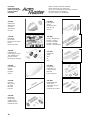
Ersatzteile (bitte bei Ihrem Fachhändler bestellen)
Replacement parts (please order from your model shop)
Pièces de rechanges (S.V.P. à ne commander que chez votre revendeur)
Parti di ricambio (da ordinare presso il rivenditore)
Repuestos (por favor, diríjase a su distribuidor)
# 22 4203
Leitwerkssatz
Tail set
Kit de gouvernes
Piani di coda
Timones
# 22 4200
Rumpf + Bowdenzüge
fuselage + snakes
fuselage + tringlerie
fusoliera + bowden
fuselage + trans.bowden
# 22 4202
Tragflächen
Wings
ailes
ali
alas
# 22 4205
Kleinteilesatz
Small items set
Petit nécessaire
Minuteria
Piezas pequeñas
# 22 4204
Radverkleidungen
Wheel spats
carrénages de roues
copri ruota
protección para ruedas
# 22 4207
Spinner EPP
Spinner EPP
Cône EPP
ogiva in EPP
cono EPP
# 72 4390
Dekorbogen
Decal sheet
Planche de décoration
Decals
Lámina decorativa
# 22 4206
Fahrwerkssatz
Undercarriage compon.
Train d’atterrissage
Parti per carrello
Kit del tren de aterrizaje
# 22 4201
Kabinenhaube
Canopy
Verrière
Capottina
Cabina
# 72 3187
Holmrohr
Wing joniner
Clé d´aile
Baionetta
Larguero
# 33 2686
Motorträger
Motor mount
Support moteur
Supporto motore
Soporte del motor
-
 1
1
-
 2
2
-
 3
3
-
 4
4
-
 5
5
-
 6
6
-
 7
7
-
 8
8
-
 9
9
-
 10
10
-
 11
11
-
 12
12
-
 13
13
-
 14
14
-
 15
15
-
 16
16


MULTIPLEX Acro Master Building Instructions
- Categoria
- Giocattoli
- Tipo
- Building Instructions
in altre lingue
- English: MULTIPLEX Acro Master
Documenti correlati
-
MULTIPLEX 21 4215 Manuale del proprietario
-
MULTIPLEX Twister Assembly Manual
-
HiTEC GEMINI Manuale del proprietario
-
-
-
MULTIPLEX Funcub Manuale del proprietario
-
-
-
MULTIPLEX FunJet Building Instructions
-
HiTEC Mentor Manuale utente