Moog FCH SERIES Istruzioni per l'uso
- Categoria
- Telecamere di sicurezza
- Tipo
- Istruzioni per l'uso
La pagina sta caricando ...
La pagina sta caricando ...
La pagina sta caricando ...

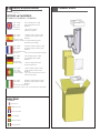
Contents of Box
24Vac: 17 watts Heater (16 watts), Blower (1 watt)
12Vdc: 7 watts Heater (6 watts), Blower (1 watt)
PoE: IEEE802.at
Camera Power:
Tools Required: .100” Flat head screwdriver
Phillips head screwdriver
24Vac: 17 vatios Calentador (16 vatios), soplador (1 vatio)
12Vdc: 7 vatios Calentador (6 vatios), soplador (1 vatio)
PoE: IEEE802.at
Energía de la cámara:
Herramientas requeridas: .100” destornillador principal plano
Destornillador principal Phillips
24Vac: 17 watts Réchauffeur (16 watts), ventilateur (1 watt)
12Vdc: 7 watts Réchauffeur (6 watts), ventilateur (1 watt)
PoE : IEEE802.at
Puissance d'appareil-photo:
Outils requis : .100 » tournevis principal plat Tournevis phillips
24Vac: 17 Watt Heizung (16 Watt), Gebläse (1 Watt)
12Vdc: 7 Watt Heizung (6 Watt), Gebläse (1 Watt)
PoE: IEEE802.at
Kamera-Energie:
Werkzeuge erfordert: .100“ acher Hauptschraubenzieher
Kreuzkopfschraubenzieher
24Vac: 17 watts Calefator (16 watts), ventilador (1 watt)
12Vdc: 7 watts Calefator (6 watts), ventilador (1 watt)
Ponto de entrada: IEEE802.at
Ferramentas exigidas: .100” chave de fenda principal lisa Chave de
fenda principal de Phillips
24Vac: 17 watt Riscaldatore (16 watt), ventilatore (1 watt)
12Vdc: 7 watt Riscaldatore (6 watt), ventilatore (1 watt)
PoE: IEEE802.at
Potere della macchina fotograca:
Gli attrezzi hanno richiesto: .100„ cacciaviti capi piani Cacciavite phillips
FCH360C2W / FCH360C2WY / FCH360C8WY
FCH360CW
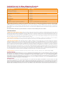
OUTDOOR and PoE MODELS:
Indoor Model:
No Electronics
Ninguna electrónica
Aucune électronique
Keine Elektronik
Nenhuma eletrônica
Nessun'elettronica
Français
FCH360 Series
Electrical Specifications
Power 24Vac / 12Vdc
Class 2 Only
!!
Deutsch
Italiano
Portuguese
Español
English
Français
Deutsch
Italiano
Portuguese
Español
English

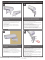
If you are running a conduit to the housing, rst
install the appropriate tting to the wall mount.
• Si usted está funcionando con un conducto a la cubierta, primero instale
la guarnición apropiada al montaje de la pared.
• Si vous courez un conduit au logement, installez d'abord l'ajustage de
précision approprié sur le bâti de mur.
• Wenn Sie ein Rohr zum Gehäuse laufen lassen, bringen Sie zuerst die
passende Befestigung zur Wandeinfassung an.
• Se você está funcionando uma canalização à carcaça, instale
primeiramente o encaixe apropriado à montagem da parede.
• Se stiate facendo funzionare un condotto all'alloggiamento, in primo
luogo installi il montaggio adatto al supporto della parete.
Attach mount to wall with suitable hardware
(not provided).
• Ate el montaje a la pared con el hardware conveniente
(no proporcionado).
• Attachez le bâti au mur avec le matériel approprié (non fourni).
• Bringen Sie Einfassung zur Wand mit der verwendbaren Hardware an
(nicht bereitgestellt).
• Una a montagem à parede com a ferragem apropriada (não fornecida).
• Attacchi il supporto alla parete con ssaggi adatti (non forniti).
WALL MOUNTING
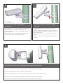
If attaching to pole, rst break away tabs with pliers and
remove (4) strap plugs.
• Si atan al poste, el primeros rompen lejos lengüetas con los alicates
y quitan (4) los enchufes de la correa.
• Si attachant au poteau, les premiers cassent loin des étiquettes avec
des pinces et enlèvent (4) des prises de courroie.
• Bei der Befestigung zum Pfosten, brechen erste weg Vorsprünge mit
Zangen und entfernen (4) Bügelstecker.
• Se unindo ao pólo, o primeiros quebram afastado abas com alicates
e removem (4) plugues da cinta.
• Se attaccando al palo, i primi rompono via le linguette con le pinze e
rimuovono (4) la cinghia tappa.
TAB
POLE MOUNTING
N O T E : T H E F O L L O W I N G I N S T R U C T I O N S M A I N LY S H O W T H E F C H 3 6 0 C W,
B U T T H E S E I N S T R U C T I O N S A R E A P P L I C A B L E T O A L L F C H 3 6 0 M O D E L S .
Lossen and then rotate the wall mount to achieve the
proper orientation.
• Aoje y gire el soporte de pared para conseguir la orientación adecuada.
• Desserrer et puis tourner le support mural pour atteindre le bon sens.
• Lösen und drehen Sie dann die Wandhalterung, um die richtige
Ausrichtung zu erreichen.
• Solte e, em seguida, gire o suporte de parede para alcançar a
orientação adequada.
• Allentare e quindi ruotare il supporto a parete per raggiungere il
corretto orientamento.
Twist
Rotate
21
3
4
Recommended Hardware for the Mounting Holes: • 5/16” - 18 (or M8 for metric) x minimum 1 ¼” Hex Head Bolt • 5/16” Flat Washer
• 5/16” Lock Washer

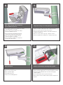
Hinge housing away from mount by loosening (2)
rear screws.
• Abisagre la cubierta lejos del montaje aojando (2) los tornillos
posteriores.
• Articulez le logement à partir du bâti en desserrant (2) les vis arrière.
• Lagern Sie Gehäuse weg von Einfassung schwenkbar, indem Sie (2)
hintere Schrauben lösen.
• Articule a carcaça longe da montagem afrouxando (2) os parafusos
traseiros.
• Alloggiamento della cerniera a partire dal supporto allentando (2) viti
posteriori.
Attach mount to pole with suitable hardware
(not provided).
• Ate el montaje al poste con el hardware conveniente (no proporcionado).
• Attachez le bâti au poteau avec le matériel approprié (non fourni).
• Bringen Sie Einfassung zum Pfosten mit der verwendbaren Hardware an
(nicht bereitgestellt).
• Una a montagem ao pólo com a ferragem apropriada (não fornecida).
• Attacchi il supporto al palo con ssaggi adatti (non forniti).
TAB
* Max Strap Width: 0.75”
6
Run cables through mount either by conduit input or through the back of the mount.
• Funcione con los cables montan a través por el conducto entrado o a través de la parte posterior del montaje.
• Courez les câbles montent à travers par le conduit entré ou par le dos du bâti.
• Laufen lassen Sie Kabel anbringen durch entweder durch das eingegebene Rohr oder durch die Rückseite der Einfassung.
• Funcione cabos montam completamente pela canalização entrada ou através da parte traseira da montagem.
• Faccia funzionare i cavi attraverso montano dal condotto immesso o tramite la parte posteriore del supporto.
7
5

Pass cables through wiring membranes
(use screwdriver to pierce).
.
• Pase los cables a través de las membranas del cableado
(el destornillador del uso a perforar) .
• Passez les câbles par des membranes de câblage
(le tournevis d'utilisation à percer).
• Führen Sie Kabel durch Verdrahtungsmembranen
(zu durchbohren der Gebrauchschraubenzieher) .
• Passe cabos através das membranas da ação
(a chave de fenda do uso a perfurar).
• Passi i cavi tramite le membrane dei collegamenti
(cacciavite di uso da perforare).
Hinge the housing closed and tighten (2) rear screws.
.
• Abisagre la cubierta cerrada y apriete (2) los tornillos posteriores.
• Articulez le logement fermé et serrez (2) les vis arrière.
• Lagern Sie das geschlossene Gehäuse schwenkbar und ziehen Sie
(2) hintere Schrauben fest.
• Articule a carcaça fechado e aperte (2) os parafusos traseiros.
• Munisca l'alloggiamento di cardini chiuso e stringa (2) viti posteriori.
Open housing lid.
.
• Abra la tapa de la cubierta.
• Ouvrez le couvercle de logement.
• Öffnen Sie Gehäusekappe.
• Abra a tampa da carcaça.
• Apra il coperchio dell'alloggiamento.
Remove camera tray by squeezing tabs together.
.
• Quite la bandeja de la cámara exprimiendo lengüetas juntas.
• Enlevez le plateau d'appareil-photo en serrant des étiquettes ensemble.
• Entfernen Sie Kamerabehälter, indem Sie zusammen Vorsprünge
zusammendrücken.
• Remova a bandeja da câmera espremendo abas junto.
• Rimuova insieme il vassoio della macchina fotograca comprimendo le
linguette.
TAB
TAB
8
9
10
11

Mount camera with ¼-20 hardware. Position the lens as shown and center with the spacers as needed, conrm
tabs are securely snapped into place. NOTE: Take care not to scratch dome with lens case.
• Monte la cámara con ¼ -20 hardware. Coloque el lente como se muestra y centro con los espaciadores según sea necesario,
conrmar pestañas estén bien encajados. NOTA: Tenga cuidado de no rayar cúpula con estuche.
• Montage de la caméra avec ¼ -20 matériel. Positionnez l'objectif dans le centre et avec les entretoises au besoin,
conrmer onglets sont correctement enclenché. REMARQUE: Veillez à ne pas rayer dôme avec étui à lentilles.
• Mount Kamera mit ¼ -20 Hardware. Positionieren Sie das Objektiv wie abgebildet und in der Mitte mit den Abstandshaltern wie nötig,
werden sicher einrastet bestätigen Registerkarten. HINWEIS: Achten Sie darauf, Kuppel mit Linsenbehälter kratzen.
• Suporte de câmera com ¼ de hardware -20. Posicione a lente como mostrado e centro com os espaçadores, conforme necessário,
conrme guias são bem encaixada no lugar. NOTA: Tome cuidado para não arranhar cúpula com lente caso.
• Montare con fotocamera ¼ -20 hardware. Posizionare la lente come mostrato e centro con i distanziali, se necessario,
vericare le schede siano correttamente scattati in posizione. NOTA: Fare attenzione a non grafare cupola con portalenti.
- ALIGN LENS -
Spacer
- TOP VIEW-
Detail
12
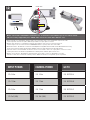
INPUT POWER CAMERA POWER GO TO
⇒
24Vac ⇒ 24Vac ⇒ SECTION A
⇒ 12Vdc ⇒ 12Vdc ⇒ SECTION B
⇒ 24Vac ⇒ 12Vdc ⇒ SECTION C
⇒ PoE (30W) ⇒ PoE (30W) ⇒ SECTION D

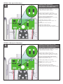
- Terminate incoming voltage as shown.
- Install shunts on “12Vdc” jumpers as shown.
- Power output to camera will be 12Vdc.
• Termine el voltaje entrante como se muestra.
- Instale la desviación en el puente “12Vdc” como se muestra.
- La salida de energía a la cámara será 12Vdc.
• Terminez la tension entrante comme montrée.
- Installez le shunt sur le pullover « 12Vdc » comme montré.
- Le rendement de puissance à l'appareil-photo sera 12Vdc.
• Beenden Sie ankommende Spannung wie gezeigt.
- Bringen Sie Shunt auf Überbrücker „12Vdc“ wie gezeigt an.
- Abgabeleistung zur Kamera ist 12Vdc.
• Termine a tensão entrante como mostrada.
- Instale a derivação na ligação em ponte “12Vdc” como
mostrada.
- A saída de poder à câmera será 12Vdc.
• Termini la tensione ricevuta come indicata.
- Installi lo shunt sul ponticello “12Vdc„ come indicato.
- L'output di forza motrice alla macchina fotograca sarà 12Vdc.
SHUNTS
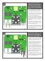
- Terminate power and data lines.
- Install shunts on “24Vac” jumpers as shown.
- Power output to camera will be 24Vac.
• Termine las líneas de la energía y de datos.
- Instale la desviación en el puente “24Vac” como se muestra.
- La salida de energía a la cámara será 24Vac.
• Terminez les lignes de puissance et de données.
- Installez le shunt sur le pullover « 24Vac » comme montré.
- Le rendement de puissance à l'appareil-photo sera 24Vac.
• Beenden Sie Energie und Datenleitungen.
- Bringen Sie Shunt auf Überbrücker „24Vac“ wie gezeigt an.
- Abgabeleistung zur Kamera ist 24Vac.
• Termine linhas do poder e de dados.
- Instale a derivação na ligação em ponte “24Vac” como
mostrada.
- A saída de poder à câmera será 24Vac.
• Termini le linee di dati e di potere.
- Installi lo shunt sul ponticello “24Vac„ come indicato.
- L'output di forza motrice alla macchina fotograca sarà 24Vac.
SHUNTS
SECTION A: 24Vac Input for 24Vac Camera
SECTION B: 12Vdc Input for 12Vdc Camera
A
B

NOTE:
To maximize power for the camera and heater option, the unit
requires that you calibrate the enclosure. During calibration,
the onboard processor intelligently determines the maximum
safe power output of the midspan, and ensures that the
enclosure does not exceed that limit. Once calibration is
complete the required values are stored in permanent
memory, with no additional calibration required.
• Para maximizar la potencia de la opción de cámara y la calefacción, la unidad requiere
que calibre la caja. Durante la calibración, el procesador de a bordo determina de forma
inteligente la potencia máxima seguridad del centro de la luz, y asegura que el recinto no
exceda de ese límite. Una vez que la calibración se ha completado los valores requeridos
se almacenan en la memoria permanente, sin calibración adicional.
• Pour maximiser la puissance de l'option appareil photo et le chauffage, l'unité exige
que vous calibrer l'enceinte. Lors de l'étalonnage, le processeur embarqué détermine
intelligemment la puissance de sortie maximale de sécurité de l'injecteur, et veille à ce
que l'enceinte ne dépasse pas cette limite. Une fois l'étalonnage est terminé, les valeurs
requises sont stockées dans la mémoire permanente, sans étalonnage supplémentaire
n'est nécessaire.
• Um Strom für die Kamera und Heizung Option zu maximieren, setzt das Gerät, dass
Sie das Gehäuse zu kalibrieren. Während der Kalibrierung der Onboard-Prozessor
ermittelt intelligent die maximale sichere Leistung der Feldmitte, und sorgt dafür, dass
das Gehäuse nicht überschreitet diese Grenze. Sobald die Kalibrierung abgeschlossen
ist die geforderten Werte im permanenten Speicher abgelegt werden, ohne zusätzliche
Kalibrierung erforderlich.
• Para maximizar a potência para a opção câmera e aquecedor, a unidade exige que você
calibrar o gabinete. Durante a calibragem, o processador de bordo inteligentemente
determina a potência de saída máxima de segurança do midspan, e assegura que o
invólucro não exceder o limite. Uma vez que a calibração é completar os valores
necessários são armazenados na memória permanente, sem calibração adicional
necessário.
• Per massimizzare la potenza per l'opzione della fotocamera e il riscaldatore, l'unità
richiede la calibrazione del contenitore. Durante la calibrazione, il processore a bordo
determina in modo intelligente la potenza massima sicurezza del midspan, e assicura
che la custodia non superi tale limite. Una volta calibrazione è completa dei necessari
valori memorizzati nella memoria permanente, senza calibrazione aggiuntiva richiesta.
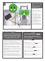
SECTION D: PoE 30W Input for 30W Camera
WARNING!
• The heater and blower will not start for 60 seconds
after power is applied to the product.
• Wait for the camera to completely boot up before
pressing the calibration button. This will allow for the
most accurate calibration.
• The heater and blower will not start for 60 seconds after power is applied to the product.
• Wait for the camera to completely boot up before pressing the calibration button. This
will allow for the most accurate calibration.
• Le chauffage et de ventilation ne démarre pas pendant 60 secondes après mise sous
tension est appliquée au produit.
• Attendez que l'appareil photo à démarrer complètement avant appuyant sur le bouton
d'étalonnage. Cela permettra pour le calibrage le plus précis.
• Die Heizung und das Gebläse wird nicht für 60 Sekunden nach dem Einschalten starten,
um das Produkt angewendet wird.
• Warten Sie, bis sich die Kamera komplett hochfahren, bevor Sie die Kalibrierung Taste.
Dies wird für die genaue Kalibrierung ermöglichen.
• Aquecedor e soprador A não será iniciado durante 60 segundos após a energia é aplicada
ao produto.
• Aguarde até que a câmera completamente arrancar antes de premir o botão de
calibração. Isto irá permitir a calibração mais precisas.
• Il riscaldamento e sofante non inizierà per 60 secondi dopo l'alimentazione è applicata
al prodotto.
• Attendere che la macchina fotograca per avviare completamente a prima di premere il
pulsante di calibrazione. Questo permetterà la taratura più accurata.
Black (-)
Red (+)
Power to Camera (12Vdc)
{
24Vac
IN
Y.
P
U
R
P
.
(
Y
E
L
L
O
W
)
(
P
U
R
P
L
E
)
- Terminate incoming 24Vac on board.
- Shunts should be installed on 24Vac
jumpers.
- Terminate the 12Vdc leads (coming
from power supply mounted on
husing lid) into corresponding
terminals on camera.
• Terminar 24Vac entrantes a bordo.
- Las derivaciones se deben instalar en los puentes
de 24 VAC.
- Terminar los conductores de 12 VCC (procedente
de la fuente de alimentación montada en la tapa
Husing) en los terminales correspondientes de la
cámara.
• Mettre n à 24Vac entrants à bord.
- Shunts doivent être installés sur les cavaliers 24Vac.
- Terminer les ls 12Vdc (en provenance de
l'alimentation monté sur Hüsing couvercle) dans les
terminaux correspondants sur l'appareil photo.
• Beenden Sie eingehende 24Vac an Bord.
- Shunts sollte auf 24Vac Jumper installiert werden.
- Beenden Sie die Leads 12Vdc (kommend von der
Stromversorgung auf Hüsing Deckel montiert) in
entsprechende Endgeräte vor der Kamera.
• Encerra 24Vac entrada a bordo.
- Shunts deve ser instalado em jumpers 24VAC.
- Terminar as ligações 12VDC (proveniente de fonte
de alimentação montada no Hüsing tampa) em
terminais correspondentes na câmera.
• Termina 24Vac in arrivo a bordo.
- Shunt deve essere installato su ponticelli 24Vac.
- Terminare i cavi 12Vdc (provenienti dalla rete di
alimentazione montato su husing coperchio) nei
terminali corrispondenti sulla macchina fotograca.
SECTION C: 12Vac Input for 12Vdc Camera
C

Connect the network cable from the
midspan to the connector that is labeled
“To Network” connect the camera to the
connector labeled “To Camera”. When
power is applied the “Heat” LED will turn
ON for 5 seconds. 60 seconds the blower
will start.
• Conecte el cable de red del centro de la luz en el conector
que tiene la etiqueta "Para Red", conecte la cámara al
conector con la etiqueta "Para la cámara". Cuando la
energía se aplica el "calor" LED se encenderá durante 5
segundos. 60 segundos, el ventilador se enciende.
• Branchez le câble réseau de la mi-portée sur le connecteur
qui est étiqueté «Pour Réseau" connecter l'appareil photo
au connecteur marqué "à la caméra". Lorsqu'une tension
est appliquée la "chaleur" LED s'allume pendant 5
secondes. 60 secondes le ventilateur démarre.
• Schließen Sie das Netzwerkkabel aus dem Midspan an
den Anschluss, die den Namen "Zum Network" schließen
Sie die Kamera an den Anschluss mit der Aufschrift "Zur
Kamera". Wenn die Macht der "Heat" wird angewendet
LED für 5 Sekunden einzuschalten. 60 Sekunden das
Gebläse startet.
• Conecte o cabo de rede do midspan ao conector que
é rotulado de "rede" conectar a câmera ao conector
identicado como "Para Camera". Quando a energia
é aplicada a "Heat" LED irá acender por 5 segundos.
60 segundos, o ventilador começará.
• Collegare il cavo di rete dal midspan al connettore che
viene etichettato come "alla rete" collegare la fotocamera
al connettore etichettato "Per Camera". Quando il potere
è applicato il "Heat" LED si accende per 5 secondi. 60
secondi il ventilatore si avvia.
To Network To Camera
Press the Calibration button for one second.
Both the Test and Heat LED will turn ON.
Once the unit has been successfully
calibrated, the Test and Heat LED will turn
OFF. Once this is complete the Heat LED
will turn ON only if the heater is ON.
• Pulse el botón de calibración durante un segundo. Tanto la
prueba y el calor se encenderá. Una vez que la unidad ha
sido calibrado correctamente, la prueba y el calor del LED
se apagará. Una vez que se trata de completar el calor se
encenderá sólo si el calentador está encendido.
• Appuyez sur le bouton d'étalonnage pour une seconde.
Tant le test et la chaleur LED s'allume. Une fois l'appareil
a été étalonné avec succès, le test et la chaleur LED
s'éteindra. Une fois cette opération terminée, la chaleur
LED s'allume que si le chauffage est allumé.
• Drücken Sie die Taste Kalibrierung für eine Sekunde.
Sowohl der Test-und Wärme-LED leuchtet auf. Sobald
das Gerät erfolgreich kalibriert wurde, wird die Test-und
Wärme-LED auszuschalten. Sobald dies abgeschlossen
ist die Wärme-LED leuchtet auf, wenn die Heizung an ist.
• Pressione o botão de calibração para um segundo.
Tanto o teste como calor LED acenderá. Uma vez que
o aparelho foi calibrado com sucesso, o teste e calor
LED apaga-se. Uma vez que este é completar o calor
LED acenderá se o aquecedor está ligado.
• Premere il pulsante di calibrazione per un secondo. Sia
il test e di calore LED si accende. Una volta che l'unità è
stata correttamente calibrata, il collaudo e calore LED si
spegne. Una volta che questo è completare il calore LED
si accende solo se il riscaldatore è ON.
Test LED
Heat LED
Calibration
Button
D
D

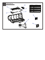
The camera tray can be securely locked into place with
the provided 3.5 x 7mm screw. Tighten it through the
rear tray tab.
.
• La bandeja de la cámara se puede trabar con seguridad en lugar con el
tornillo proporcionado de 3.5 x de 7m m. Apriétela a través de la
lengüeta posterior de la bandeja.
• Le plateau d'appareil-photo peut être solidement fermé à clef sur
l'endroit avec la vis fournie de 3.5 x de 7mm. Serrez-le par l'étiquette
arrière de plateau.
• Der Kamerabehälter kann in Platz mit der zur Verfügung gestellten 3.5 x
7mm Schraube sicher verriegelt werden. Ziehen Sie ihn durch den
hinteren Behältervorsprung fest.
• A bandeja da câmera pode ser rmemente fechado no lugar com o
parafuso fornecido de 3.5 x de 7mm. Aperte-a através da aba traseira da
bandeja.
• Il vassoio della macchina fotograca può essere saldamente bloccato nel
posto con la vite fornita di 7mm x di 3.5. Stringalo attraverso la linguetta
posteriore del vassoio.
Close the housing lid and securely tighten the
(2) lid screws.
.
• Cierre la tapa de la cubierta y apriete con seguridad (2) los tornillos
de la tapa.
• Fermez le couvercle de logement et serrez solidement (2) les vis
de couvercle.
• Schließen Sie die Gehäusekappe und ziehen Sie sicher die (2)
Kappenschrauben fest.
• Feche a tampa da carcaça e aperte rmemente (2) os parafusos
da tampa.
• Chiuda il coperchio dell'alloggiamento e saldamente stringa (2) il
coperchio avvita.
16
15
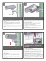
Adjust the aim of the housing by loosening the
screw on the mount arm.
.
• Ajuste la puntería de la cubierta aojando el tornillo en el brazo
del montaje.
• Ajustez le but du logement en desserrant la vis sur le bras de bâti.
• Justieren Sie das Ziel des Gehäuses, indem Sie die Schraube am
Einfassungsarm lösen.
• Ajuste o alvo da carcaça afrouxando o parafuso no braço da montagem.
• Registri lo scopo dell'alloggiamento allentando la vite sul braccio del
supporto.
Hex tool
After powering your system up, make necessary
focus and camera adjustments.
.
• Después de accionar su sistema para arriba, haga los ajustes
necesarios del foco y de la cámara.
• Après avoir mis votre système, faites les ajustements nécessaires
de foyer et d'appareil-photo.
• Nachdem Sie oben Ihr System angetrieben haben, nehmen Sie
notwendige Fokus- und Kamerajustagen vor.
• Após ter psto seu sistema acima, faça ajustes necessários do foco
e da câmera.
• Dopo la potenza del vostro sistema in su, procedi alle registrazioni
necessarie della macchina fotograca e del fuoco.
13
14

If your housing has a sunshield, adjust it for your
particular lighting conditions by loosening (2) screws.
.
• Si su cubierta tiene un sunshield, ajústelo para que haya sus condiciones
de iluminación particulares aojando (2) los tornillos.
• Si votre logement a un sunshield, ajustez-le à vos états d'éclairage
particuliers en desserrant (2) des vis.
• Wenn Ihr Gehäuse ein sunshield hat, stellen Sie es auf Ihre bestimmten
Beleuchtungzustände ein, indem Sie (2) Schrauben lösen.
• Se sua carcaça tem um sunshield, ajuste-o para suas condições de
iluminação particulares afrouxando (2) os parafusos.
• Se il vostro alloggiamento ha un sunshield, registrilo per ottenere le
vostre condizioni di luce particolari allentando (2) avvita.
17
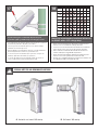
Wire Gauge
Total vA
consumed
,5
22
,75
20
1,0
18
1,5
16
2,5
14
4
12
6
10
MM
2
AWG
5.5
ft
m
400
121
600
182
960
292
- - -
10
120
36.5
180
54.9
300
91.4
480
146
800
243
1300
396
-
20
86
27.1
141
43.0
225
68.6
358
109
571
174
905
275
1440
438
30
65
19.8
90
27.4
130
39.6
225
68.6
350
106
525
160
830
252
40
44
13.4
70
21.3
112
34.1
179
54.6
285
86.9
452
138
720
219
50
35
10.6
56
17.1
90
27.4
143
43.6
228
69.5
362
110
576
175
60
29
9.4
47
14.3
75
22.9
119
36.2
190
57.9
301
91.7
480
146
70
25
8.8
40
12.2
64
19.5
102
31.1
163
49.7
258
78.6
411
125
80
31
7.6
34
10.3
55
16.8
85
25.9
140
42.7
215
65.5
340
103
These are recommended maximum distances
for 24VAC with a 10% voltage drop.
• Éstos se recomiendan las distancias máximas para
24VAC con una caída de voltaje del 10%.
• Ceux-ci sont recommandés des distances maximum
pour 24VAC avec une chute de tension de 10%.
• Diese werden maximale Abstände für 24VAC mit
einem 10% Spannungsabfall empfohlen.
• Estes são recomendados distâncias máximas para
24VAC com uma queda de tensão de 10%.
• Questi sono suggeriti distanze massime per 24VAC con
una differenza de potenziale di 10%.
18
SPECIAL NOTE FOR 360 VIEWING APPLICATIONS
A. Horizontal mast mount 360 viewing B. Wall mount 360 viewing
!!
La pagina sta caricando ...
La pagina sta caricando ...
-
 1
1
-
 2
2
-
 3
3
-
 4
4
-
 5
5
-
 6
6
-
 7
7
-
 8
8
-
 9
9
-
 10
10
-
 11
11
-
 12
12
-
 13
13
-
 14
14
-
 15
15


Moog FCH SERIES Istruzioni per l'uso
- Categoria
- Telecamere di sicurezza
- Tipo
- Istruzioni per l'uso
in altre lingue
Documenti correlati
Altri documenti
-
Moog Videolarm PFH10C2W Installation And Operation Instructions Manual
-
-
-
Moog Videolarm SM75CF2N Installation And Operation Instructions Manual
-
-
Moog Videolarm FDW75CF2N Installation And Operation Instructions Manual
-
-
-
-