
ISTRUZIONI PER L’USO – NORME DI INSTALLAZIONE
USE AND INSTALLATION INSTRUCTIONS
INSTRUCTIONS POUR L’EMPLOI – NORMES D’INSTALLATION
INSTRUCCIONES PARA EL USO – NORMAS DE INSTALACIÓN
BETRIEBSANLEITUNG - INSTALLATIONSVORSCHRIFTEN
Geo 03
24V
Geo 03
24V

AVVERTENZE PER L’INSTALLATORE
OBBLIGHI GENERALI PER LA SICUREZZA
1) ATTENZIONE! È importante per la sicurezza delle persone seguire
attentamente tutta l’istruzione. Una errata installazione o un errato uso del
prodotto può portare a gravi danni alle persone.
2) Leggere attentamente le istruzioni prima di iniziare l’installazione del
prodotto.
3) I materiali dell’imballaggio (plastica, polistirolo, ecc.) non devono
essere lasciati alla portata dei bambini in quanto potenziali fonti di
pericolo.
4) Conservare le istruzioni per riferimenti futuri.
5) Questo prodotto è stato progettato e costruito esclusivamente per
l’utilizzo indicato in questa documentazione. Qualsiasi altro utilizzo non
espressamente indicato potrebbe pregiudicare l’integrità del prodotto
e/o rappresentare fonte di pericolo.
6) GENIUS declina qualsiasi responsabilità derivata dall’uso improprio o
diverso da quello per cui l’automatismo è destinato.
7) Non installare l’apparecchio in atmosfera esplosiva: la presenza di gas
o fumi infiammabili costituisce un grave pericolo per la sicurezza.
8) Gli elementi costruttivi meccanici devono essere in accordo con
quanto stabilito dalle Norme EN 12604 e EN 12605.
Per i Paesi extra-CEE, oltre ai riferimenti normativi nazionali, per ottenere un
livello di sicurezza adeguato, devono essere seguite le Norme sopra
riportate.
9) GENIUS non è responsabile dell’inosservanza della Buona Tecnica nella
costruzione delle chiusure da motorizzare, nonché delle deformazioni
che dovessero intervenire nell’utilizzo.
10) L’installazione deve essere effettuata nell’osservanza delle Norme EN
12453 e EN 12445. Il livello di sicurezza dell’automazione deve essere
C+E.
11) Prima di effettuare qualsiasi intervento sull’impianto, togliere
l’alimentazione elettrica.
12) Prevedere sulla rete di alimentazione dell’automazione un interruttore
onnipolare con distanza d’apertura dei contatti uguale o superiore a 3
mm. È consigliabile l’uso di un magnetotermico da 6A con interruzione
onnipolare.
13) Verificare che a monte dell’impianto vi sia un interruttore differenziale
con soglia da 0,03 A.
14) Verificare che l’impianto di terra sia realizzato a regola d’arte e
collegarvi le parti metalliche della chiusura.
15) L’automazione dispone di una sicurezza intrinseca antischiacciamento
costituita da un controllo di coppia. E' comunque necessario verificarne
la sogli di intervento secondo quanto previsto dalle Norme indicate al
punto 10.
16) I dispositivi di sicurezza (norma EN 12978) permettono di proteggere
eventuali aree di pericolo da Rischi meccanici di movimento, come ad
Es. schiacciamento, convogliamento, cesoiamento.
17) Per ogni impianto è consigliato l’utilizzo di almeno una segnalazione
luminosa nonché di un cartello di segnalazione fissato adeguatamente
sulla struttura dell’infisso, oltre ai dispositivi citati al punto “16”.
18) GENIUS declina ogni responsabilità ai fini della sicurezza e del buon
funzionamento dell’automazione, in caso vengano utilizzati componenti
dell’impianto non di produzione GENIUS.
19) Per la manutenzione utilizzare esclusivamente parti originali GENIUS.
20) Non eseguire alcuna modifica sui componenti facenti parte del
sistema d’automazione.
21) L’installatore deve fornire tutte le informazioni relative al funzionamento
manuale del sistema in caso di emergenza e consegnare all’Utente
utilizzatore dell’impianto il libretto d’avvertenze allegato al prodotto.
22) Non permettere ai bambini o persone di sostare nelle vicinanze del
prodotto durante il funzionamento.
23) Tenere fuori dalla portata dei bambini radiocomandi o qualsiasi altro
datore di impulso, per evitare che l’automazione possa essere azionata
involontariamente.
24) Il transito tra le ante deve avvenire solo a cancello completamente
aperto.
25) L’Utente utilizzatore deve astenersi da qualsiasi tentativo di riparazione
o d’intervento diretto e rivolgersi solo a personale qualificato.
26) Tutto quello che non è previsto espressamente in queste istruzioni non è
permesso
IMPORTANT NOTICE FOR THE INSTALLER
GENERAL SAFETY REGULATIONS
1) ATTENTION! To ensure the safety of people, it is important that you read all
the following instructions. Incorrect installation or incorrect use of the
product could cause serious harm to people.
2) Carefully read the instructions before beginning to install the product.
3) Do not leave packing materials (plastic, polystyrene, etc.) within
reach of children as such materials are potential sources of danger.
4) Store these instructions for future reference.
5) This product was designed and built strictly for the use indicated in this
documentation. Any other use, not expressly indicated here, could
compromise the good condition/operation of the product and/or be
a source of danger.
6) GENIUS declines all liability caused by improper use or use other than
that for which the automated system was intended.
7) Do not install the equipment in an explosive atmosphere: the presence
of inflammable gas or fumes is a serious danger to safety.
8) The mechanical parts must conform to the provisions of Standards EN
12604 and EN 12605.
For non-EU countries, to obtain an adequate level of safety, the Standards
mentioned above must be observed, in addition to national legal
regulations.
9) GENIUS is not responsible for failure to observe Good Technique in the
construction of the closing elements to be motorised, or for any
deformation that may occur during use.
10) The installation must conform to Standards EN 12453 and EN 12445. The
safety level of the automated system must be C+E.
11) Before attempting any job on the system, cut out electrical power.
12) The mains power supply of the automated system must be fitted with
an all-pole switch with contact opening distance of 3mm or greater.
Use of a 6A thermal breaker with all-pole circuit break is recommended.
13) Make sure that a differential switch with threshold of 0.03 A is fitted
upstream of the system.
14) Make sure that the earthing system is perfectly constructed, and
connect metal parts of the means of the closure to it.
15) The automated system is supplied with an intrinsic anti-crushing safety
device consisting of a torque control. Nevertheless, its tripping threshold
must be checked as specified in the Standards indicated at point 10.
16) The safety devices (EN 12978 standard) protect any danger areas
against mechanical movement Risks, such as crushing, dragging, and
shearing.
17) Use of at least one indicator-light is recommended for every system,
as well as a warning sign adequately secured to the frame structure, in
addition to the devices mentioned at point “16”.
18) GENIUS declines all liability as concerns safety and efficient operation
of the automated system, if system components not produced by
GENIUS are used.
19) For maintenance, strictly use original parts by GENIUS.
20) Do not in any way modify the components of the automated system.
21) The installer shall supply all information concerning manual operation
of the system in case of an emergency, and shall hand over to the user
the warnings handbook supplied with the product.
22) Do not allow children or adults to stay near the product while it is
operating.
23) Keep remote controls or other pulse generators away from children,
to prevent the automated system from being activated involuntarily.
24) Transit through the leaves is allowed only when the gate is fully open.
25) The user must not attempt any kind of repair or direct action whatever
and contact qualified personnel only.
26) Anything not expressly specified in these instructions is not permitted.
CONSIGNES POUR L'INSTALLATEUR
RÈGLES DE SÉCURITÉ
1) ATTENTION! Il est important, pour la sécurité des personnes, de suivre à la
lettre toutes les instructions. Une installation erronée ou un usage erroné du
produit peut entraîner de graves conséquences pour les personnes.
2) Lire attentivement les instructions avant d'installer le produit.
3) Les matériaux d'emballage (matière plastique, polystyrène, etc.) ne
doivent pas être laissés à la portée des enfants car ils constituent des
sources potentielles de danger.
4) Conserver les instructions pour les références futures.
5) Ce produit a été conçu et construit exclusivement pour l'usage indiqué
dans cette documentation. Toute autre utilisation non expressément
indiquée pourrait compromettre l'intégrité du produit et/ou représenter
une source de danger.
6) GENIUS décline toute responsabilité qui dériverait d'usage impropre ou
différent de celui auquel l'automatisme est destiné.
7) Ne pas installer l'appareil dans une atmosphère explosive: la présence
de gaz ou de fumées inflammables constitue un grave danger pour la
sécurité.
8) Les composants mécaniques doivent répondre aux prescriptions des
Normes EN 12604 et EN 12605.
Pour les Pays extra-CEE, l'obtention d'un niveau de sécurité approprié
exige non seulement le respect des normes nationales, mais également
le respect des Normes susmentionnées.
9) GENIUS n'est pas responsable du non-respect de la Bonne Technique
dans la construction des fermetures à motoriser, ni des déformations qui
pourraient intervenir lors de l'utilisation.
10) L'installation doit être effectuée conformément aux Normes EN 12453
et EN 12445. Le niveau de sécurité de l'automatisme doit être C+E.
11) Couper l'alimentation électrique avant toute intervention sur l'installation.
12) Prévoir, sur le secteur d'alimentation de l'automatisme, un interrupteur

1
ITALIANO
elartnecalledenoizatnemilaidenoisneT zH06/05)%01–6+(~V42
atibrossaaznetoP W3
erotom.xamociraC W08
irossecca
.xamociraC Am005cdV42
etnaiggepmal.xamociraC .xamW51cdV42
aips/aisetrocidecul.xamociraC .xamW51cdV42
etneib
maarutarepmeT C°05+C°02-
enoizetorpidelibisuF 2
otnemanoiznufidehcigoL ossapossaP/acitamotuA
arusuihc/arutr
epaidopmeT enoizallatsniidesafniotnemidnerppaotuanI
asuapidopmeT enoizallatsniidesafniotnemidnerppaotuan
I
atnipsidazroF ilibanoizelesillevileuD
otnematnellaridopmeT ilibanoizelesidnoces3o5,1
areittesromniisserg
nI
asroceniF/eirettabenoizatnemilA/~V42enoizatnemilA
arutrepaezzeruciS/ESOLC/POTS/TRATS/arusuihcearutrepa
arusuihce
oidarerottennoC itneveciroidaredehcS
areittesromnieticsU
etnaiggepmaL/cdV42erotoM/cdV42irosse
ccaenoizatnemilA
cdV42aisetrocidecuL-aipS/cdV42
adehcsinoisnemiD .mm571x09
~V032eladioroterotamrofsartehc
itsirettaraC AV08/~V22.ceS/~V032.mirP
~V511eladioroterotamrofsartehcitsirettaraC AV08/~V02.ceS/~V511.mir
P
ilanoizpoeirettabehcitsirettaraC .mm801x07x09.snemid/hA4/V21
onretsereperotinetnocehcitsirettaraC 55PI.
mm521x522x503
A
B
C
Fig. 1
APPARECCHIATURA ELETTRONICA PER BASCULANTI 24 Vdc
ISTRUZIONI PER L’USO - NORME DI INSTALLAZIONE
1. CARATTERISTICHE GENERALI
Questa centrale di comando per basculanti a 24 Vdc, grazie alla elevata potenza del microprocessore di cui è dotata, offre un ampio
numero di prestazioni e regolazioni, con rallentamento e controllo motore.
Un sofisticato controllo elettronico monitorizza costantemente il circuito di potenza ed interviene bloccando la centrale in caso di
anomalie che possano pregiudicare il corretto funzionamento della frizione elettronica.
I settaggi principali e i modi di funzionamento si effettuano mediante dip-switch mentre le regolazioni dei tempi e della potenza del
motore, si effettuano tramite autoapprendimento in fase di installazione. 8 LEDS incorporati indicano costantemente lo stato della
centrale e del motoriduttore.
2. CARATTERISTICHE TECNICHE
Attenzione: In funzione della tensione di rete si possono avere valori d’uscita diversi sulla tensione 24V~. Prima di procedere alla messa
in servizio occorre sempre verificare la tensione d’uscita del trasformatore. Questa non deve essere superiore a 26V~ sia per
l’alimentazione a 230V~ che 115V~. La tensione deve essere misurata a vuoto, ovvero con il trasformatore alimentato e scollegato dalla
scheda.
3. PREDISPOSIZIONI
ATTENZIONE: E’ importante per la sicurezza delle persone seguire attentamente tutte le avvertenze e istruzioni presenti in questo libretto.
Una errata installazione o un errato uso del prodotto può portare a gravi danni alle persone.
Verificare che a monte dell’impianto vi sia un adeguato interruttore differenziale come prerscritto dalla normativa vigente e prevedere
sulla rete di alimentazione un magnetotermico con interruzione onnipolare. Per la messa in opera dei cavi elettrici utilizzare adeguati tubi
rigidi e/o flessibili. Separare sempre i cavi di collegamento degli accessori a bassa tensione da quelli
di alimentazione a 230 V~.
Per evitare qualsiasi interferenza utilizzare guaine separate.
Nella versione con centrale nel contenitore per esterno a tenuta stagna, la lunghezza massima dei
cavi di alimentazione tra centrale e motore non deve essere superiore ai 3 m., utilizzando cavi
2x2.5mm² per il motore e 3x0.5mm² per i finecorsa.
Installazione nel contenitore stagno
Per il fissaggio dei vari componenti all’interno del contenitore stagno procedere come segue (vedi
fig. 1):
1) Fissare il supporto per il trasformatore toroidale nella posizione A con n.3 viti Ø4.2x13 autofilettanti
(fornite), ponendo i distanziali tra supporto e guide del contenitore stagno. Nota bene: il supporto
è dimensionato per alloggiare un trasformatore con caratteristiche e dimensioni specificate
nella tabella del paragrafo 2.
2) Fissare il trasformatore al supporto con le n.2 fascette (fornite).
3) Se è previsto l’utilizzo delle batterie tampone, fissare il relativo supporto nella posizione B con n.4
viti Ø3.5x9.5 autofilettanti (fornite) nei fori di incrocio delle guide del contenitore stagno.
Nota bene: il supporto è dimensionato per alloggiare n.2 batterie (non fornite) con caratteristiche
e dimensioni specificate nella tabella del paragrafo 2.
4) Posizionare le batterie sul supporto.
5) Fissare la centrale nella posizione C con n.4 viti Ø4.2x13 autofilettanti (fornite), ponendo i distan-
ziali tra scheda e guide del contenitore stagno.

2
ITALIANO
4. COLLEGAMENTI E FUNZIONAMENTO
4.1 MORSETTIERA M1
4.1.1 Alimentazione 24V
Morsetti “1-2”. Ingresso al quale va collegato il secondario con alimentazione 24V~ 50/60 Hz del trasformatore. La presenza di alimenta-
zione per mezzo del trasformatore è segnalata dall’accensione del led POWER.
4.1.2 Batterie
Morsetti “3-4”. La centrale è predisposta per poter funzionare con n.2 batterie tampone (optinal) con caratteristiche minime come
riportato in tabella del paragrafo 2. La centrale quando è alimentata, provvede a mantenere in carica le batterie. Queste entrano in
funzione nel momento in cui viene a mancare l’alimentazione del trasformatore.
Nota bene: l’alimentazione per mezzo delle batterie è da considerarsi una situazione di emergenza, il numero delle manovre possibili
è legato alla qualità delle batterie stesse, alla struttura da movimentare, da quanto tempo è passato dalla sospensione dell’alimentazione
di rete, ect., ect..
Nota bene: rispettare le polarità di alimentazione delle batterie
4.1.3 Accessori
Morsetti “5-6”. Uscita per alimentazione accessori esterni (24 Vdc).
Nota bene: il carico max degli accessori è di 500 mA.
Nota bene: rispettare le polarità di alimentazione
4.1.4 Motoriduttore
Morsetti “7-8”. Collegare il motore con alimentazione 24Vdc 80W max.
4.2 MORSETTIERA M2
4.2.1 Massa a terra
Morsetto “9”. Collegare la massa a terra della rete.
Nota bene: collegamento assolutamente necessario per il corretto funzionamento della centrale.
4.2.2 Finecorsa apertura
Morsetti “10-11”. Lo stato di questo ingresso è segnalato mediante il led FCA. Collegare il finecorsa che agisce sul movimento di apertura.
L’effetto è differente in funzione della programmazione effettuata tramite il dip-sw 3. Se non viene utilizzato il finecorsa, ponticellare
l’ingresso.
4.2.3 Finecorsa chiusura
Morsetti “10-12”. Lo stato di questo ingresso è segnalato mediante il led FCC. Collegare il finecorsa che agisce sul movimento di chiusura.
Se non viene utilizzato il finecorsa, ponticellare l’ingresso.
4.2.4 Lampeggiante
Morsetti “13-14”. Utilizzare un lampeggiatore a luce fissa (il lampeggio è determinato dalla centrale) con tensione di funzionamento
24Vdc 15W max. E’ utile collegarlo prima della fase di programmazione perchè ne indica le fasi. In apertura esegue un prelampeggio fisso
di 0.5 secondi, in chiusura di 1.5 secondi. Se è inserita la logica automatica, quando raggiunge la battuta di apertura. il lampeggiante resta
acceso fisso per 5 sec. segnalando all’utente che richiuderà automaticamente. A cancello aperto il lampeggiante è spento, lampeggia
solo nel momento in cui vengono impegnate le sicurezze per un tempo massimo di 10 sec., dopodichè si spegne anche con le sicurezze
impegnate.
4.2.5 Spia/Luce di cortesia
Morsetti “13-15”. Morsetto in parallelo con il portalampada posto sulla scheda. Utilizzare una lampada da 24Vdc 15W max. L’effetto è
differente in funzione della programmazione effettuata tramite il dip-sw 7.
4.3 MORSETTIERA M3
4.3.1 Close
Morsetti “16-21”. Lo stato di questo ingresso è segnalato mediante il led CLOSE. A questo circuito va collegato qualsiasi dispositivo (es.
pulsante, radiocomando, ect.) che, chiudendo un contatto, genera un impulso di chiusura totale.
Nota bene: Per installare più datori di impulsi collegare i contatti in parallelo.
4.3.2 Start
Morsetti “17-21”. Lo stato di questo ingresso è segnalato mediante il led START. A questo circuito va collegato qualsiasi dispositivo (es.
pulsante, radiocomando, ect.) che, chiudendo un contatto, genera un impulso d’apertura e/o chiusura totale del cancello. Il suo
funzionamento è definito dal dip-switch 5.
Nota bene: Per installare più datori di impulsi collegare i contatti in parallelo.
4.3.3 Fotocellule chiusura
Morsetti “18-21”. Lo stato di questo ingresso è segnalato mediante il led FTC. A questo circuito va collegato qualsiasi dispositivo di sicurezza
(fotocellule, costa di sicurezza, ect.) che, aprendo un contatto, ha un effetto di sicurezza sul moto di chiusura.
Nota bene: Se non vengono collegati dispositivi di sicurezza ponticellare l’ingresso. Per installare più dispositivi di sicurezza collegare
i contatti NC in serie.
4.3.4 Stop
Morsetti “19-21”. Lo stato di questo ingresso è segnalato mediante il led STP. A questo circuito va collegato qualsiasi dispositivo (es. pulsante,
pressostato, ect.) che, aprendo un contatto, arresta il moto del cancello. Solo un successivo impulso di apertura o chiusura riprende il ciclo
impostato.
Nota bene: Se non vengono collegati dispositivi di STOP ponticellare l’ingresso. Per installare più dispositivi di STOP collegare i contatti
NC in serie.
4.3.5 Fotocellule apertura
Morsetti “20-21”. Lo stato di questo ingresso è segnalato mediante il led FTO. A questo circuito va collegato qualsiasi dispositivo di sicurezza
(fotocellule, costa di sicurezza, ect.) che, aprendo un contatto, ha un effetto di sicurezza sul moto di apertura.
Nota bene: Se non vengono collegati dispositivi di sicurezza ponticellare l’ingresso. Per installare più dispositivi di sicurezza collegare
i contatti NC in serie.

3
ITALIANO
DELOSECCAOTNEPS
REWOP enoizatnemila- eteradenoizatnemilA eirettaboetnessaenoizatnemilA
ACF erpaasrocenif– otan
gepmisiD otangepmI
CCF eduihcasrocenif–otangepmisiD otangepmI
ESOLC otangepmI otangepmisiD
TRATS otangepmI otang
epmisiD
CTF arusuihcazzerucis– otangepmisiD otangepmI
PTS pots- otangepmisiD otangepm
OTF arutrepaazzerucis– ota
ngepmisiD otangepmI
ELIBISUFENOIZETORPELIBISUFENOIZETORP
02x5–V052A01T=1FenoizatnemilA/erotoM02x5–V052/51.3F=2FirosseccaaticsU/a
cigoL
5. INSERIMENTO SCHEDA RICEVITORE PER TELECOMANDO
La centrale è predisposta per alloggiare un modulo radioricevitore a 5 pin. Per procedere all’installazione togliere l’alimentazione elettrica
e inserire il modulo nell’apposito connettore M5 all’interno della centrale.
ATTENZIONE: Per non dannegiare, e quindi comprometterne irrimediabilmente il funzionamento, la ricevente deve essere innestata
rispettando l’orientamento specificato nel paragrafo 10 (Schema di collegamento).
Seguire poi le istruzioni del radio-ricevitore per la memorizzazione del telecomando. Una volta memorizzato il telecomando agisce come
un qualsiasi dispositivo di comando sullo START.
6. LEDS DI CONTROLLO
Nota bene: in neretto la condizione dei leds con automazione chiusa e centrale alimentata.
7. PROGRAMMAZIONE
NB. La programmazione deve essere eseguita con la centrale alimentata dalla rete, attraverso il trasformatore, non è possibile eseguire
la programmazione con le sole batterie tampone. Questo garantisce la corretta programmazione di tutti i tempi e funzioni della
centrale.
La programmazione dei tempi di lavoro, dei rallentamenti e della frizione elettronica avvengono in autoapprendimento, il movimento
dell’anta in questa fase avviene in maniera rallentata. Procedere quindi nel seguente modo:
1) Sbloccare l’automazione e portarla a circa metà apertura, poi ribloccarla.
2) Alimentare la centrale (l’alimentazione è segnalata dall’accensione del led POWER).
3) Spostare l’interruttore S2 su PROG, il lampeggiante si accenderà a luce fissa per segnalare che si è in fase di programmazione.
4) Premere il pulsante collegato sui morsetti di START oppure il telecomando, se già memorizzato. La prima manovra che l’automazione
compie deve essere di CHIUSURA.
5) Se l’applicazione si movimenta in apertura, toccare con un cacciavite i due pins di RESET, la centrale bloccherà immediatamente il
moto dell’automazione.
6) Togliere l’alimentazione alla centrale, invertire la polarità dei due cavi di alimentazione del motore e ripetere l’operazione dal punto
1.
7) Dopo il comando di START, l’automazione si movimenta in chiusura, fino a raggiungere la battuta di chiusura o il finecorsa, se previsto.
8) Dopo circa due secondi l’automazione riparte automaticamente in apertura, fino a raggiungere la battuta di apertura o il finecorsa,
se previsto.
9) La centrale inizia il conteggio del tempo di pausa; trascorso il tempo desiderato, premere ancora il comando di START, l’automazione
si chiuderà completamente.
10) A questo punto la fase di programmazione è terminata; riportare l’interruttore S2 su OFF, il lampeggiante si spegnerà.
8. FUNZIONAMENTO DELLA FRIZIONE ELETTRONICA DIP SWITCH 7 SU ON
Dispositivo importantissimo ai fini della sicurezza, la sua taratura resta costante nel tempo senza essere soggetta ad usure o cambiamenti
di taratura.
Essa è attiva sia in chiusura che in apertura, quando interviene inverte la marcia. In caso di chiusura automatica interviene per due volte
consecutive, la terza si posiziona in STOP disabilitando qualsiasi comando automatico; questi perchè intervenendo più volte consecu-
tivamente indica la permanenza di un ostacolo e quindi ogni ulteriore manovra potrebbe essere fonte di pericolo.
Per riavviare l’automazione l’utente dovrà eseguire un comando di apertura o chiusura.
9. FUSIBILI DI PROTEZIONE

4
ITALIANO
20191817
1615
14131211
10
9
MOT
8765
4
3
2
FTOSTPFTC
STA
FCC
FCA
7
8
56
3
412
1
CPU
RESET
S2
S1
OFF
ON
M1
M5
M3
M2
OFF
PROG
POWER
250V
F3.15A
F2
F1
21
CLOSE
enoiznuF
hctiws-piD
1WS2WS3WS4WS5WS6WS7WS8WS
acinortteleenoizirF
àtilibisnesaminim,azrofamissaM NO
àtilibisnesamis
sam,azrofaminiM FFO
acitamotuaarusuihC
atiresnI NO
atiresnisiD FFO
arutrepaasroceniflusotnematnellaR
itnavani
asroceniflad,otiresnI NO
asroceniflaotaidemmioccolb,otiresnisiD FFO
elainimodnocotnemanoiznuF
TRATSattecca
nonasuapearutrepanI NO
atiresnisiD FFO
TRATSidodnamocotnemanoiznuF
…………-erpa–pots–eduihc–pots–erpA NO
..………-
eduihc–erpa–eduihc–erpA FFO
otnematnellaridopmeT
idnoces3 NO
idnoces5,1 FFO
potsorepmaon-aips/potsorepma-ais
etrocideculenoizeleS
potsorepma-.ces09opodengepsis,aisetrocidecuL NO
potsorepomaon-eduihceasuap,erpaetna
rudasecca,aipS FFO
asrocenifenoizeleS
itatnomasrocenifiibmartnE NO
arutrepaidasrocenifolosoasrocenifazneS F
FO
TABELLA 1: LOGICHE E SETTAGGI DI FUNZIONAMENTO
230 V~ 50 Hz
Batterie
Connettore
per ricevente
Trasformatore
toroidale
Alimentazione per
accessori esterni
Motoriduttore
Lampeggiante
STOP
Terra
Spia/Luce di cortesia
Finecorsa apertura
Finecorsa chiusura
START
Luce di cortesia
Dip-switch
Ricevente
CLOSE
Fotocellule
chiusura
Fotocellule
apertura
10. SCHEMA DI FUNZIONAMENTO

5
ENGLISH
A
B
C
Fig. 1
ylppusrewoptinulortnoC zH06/05)%01–6+(~V42
rewopdebrosbA W3
daol.xamrotoM W08
daol.xamseirosseccA Am005cdV42
daol.xampmalgnihsalF .xamW51cdV42
thgil-rotacidni/thgilysetruocfodaolxaM .xamW51cdV42
erutarepmettneibmag
nitarepO C°05+C°02-
sesufnoitcetorP 2
scigolnoitcnuF deppetS/citamotuA
emitgnisolc/gninepO noitallatsnitagni
nrael-flesyB
emitesuaP noitallatsnitagninrael-flesyB
ecroftsurhT slevelelbatcelesowT
emitnoitareleceD sdnoc
eselbatceles3ro5.1
stupnidraoblanimreT
dnagninepO/ylppusrewopyrettaB/~ylppusrewop~V42
dnagninepO/ESOLC/P
OTS/TRATS/hctiws-timilgnisolc
secivedytefasgnisolc
rotcennocoidaR snip5rotcennocdipaR
stuptuodraoblanimre
T
cdV42/rotomcdV42/seirosseccaotylppusrewopcdV42
thgilysetruoC/rotacidnIcdV42/pmalgnihsalF
snoisnemiddraob-lortnoC .mm571x09
~V032remrofsnartladiorotfoscitsiretcarahC AV08/~V22.ceS/~V032.mirP
~V511remrofsnartl
adiorotfoscitsiretcarahC AV08/~V02.ceS/~V511-.mirP
seirettablanoitpofoscitsiretcarahC .mm801x07x09.snemi
d/hA4/V21
erusolcneroodtuofoscitsiretcarahC 55PI.mm521x522x503
CONTROL BOARD FOR UP-AND-OVER DOORS 24 Vdc
OPERATING INSTRUCTIONS – INSTALLATION INSTRUCTIONS
1. GENERAL CHARACTERISTICS
Thank to its high powered microprocessor, this control unit for 24 Vdc up-and-over doors , offers a wide range of functions and adjustments,
including deceleration and motor control.
A sophisticated electronic control monitors the power circuit at all times and disables the control unit in the event of malfunctions that
could impair efficiency of the electronic clutch.
Main settings and function modes are executed by dip switches, whereas timing, and also power of motor are adjusted through self-
learning at installation. 8 built-in LEDs constantly indicate status of both control unit and gearmotor.
2. TECHNICAL SPECIFICATIONS
Attention: different output values on voltage 24V~ are possible according to the mains voltage. Before starting, always check the
transformer output voltage. It shall not exceed 26V~ both for the 230V~ power supply and 115V~ power supply. Voltage is to be measured
loadless, i.e. when the transformer is supplied with power but disconnected from the board.
3. INSTRUCTIONS
WARNING: To ensure people’s safety, all warnings and instructions in this booklet must be carefully observed. Incorrect installation or
use of the product could cause serious harm to people.
Make sure there is an adequate differential switch upstream of the system as specified by current Standards, and install a thermal breaker
with all-pole switch on the electric mains.
To lay electric cables, use adequate rigid and/or flexible tubes.
Always separate connection cables of low voltage accessories from those operating at 115 / 230 V~.
To prevent any interference whatever, use separate sheaths.
Installation in the sealed enclosure
For securing the components inside the sealed enclosure proceed as follows (see fig. 1):
1) Secure the support for the toroidal transformer in position A, using three Ø4.2x13 self-tapping
screws (supplied), placing the spacers between the support and the guides of the sealed enclosure.
NB.: the support is sized to house a transformer with characteristics and dimensions specified on
the table in paragraph 2.
2) Secure the transformer to the support with 2 clamps (supplied).
3) If using buffer batteries, secure the relevant support in position B with four Ø3.5x9.5 self-tapping
screws (supplied) in the crossover holes of the guides of the sealed enclosure.
NB.: the support is sized to house 2 batteries (not supplied) with characteristics and dimensions
specified on the table in paragraph 2.
4) Position the batteries on the support.
5) Secure the control unit in position C with four Ø4.2x13 self-tapping screws (supplied), placing the
spacers between the board and the guides of the sealed enclosure.

6
ENGLISH
4. CONNECTIONS AND OPERATION
4.1 TERMINAL BOARD M1
4.1.1 24V power supply
Terminals “1-2”. This is the input to which the secondary winding of the transformer, powered at 24 V~ 50/60 Hz, should be connected. When
power is supplied by the transformer, this is signalled by the POWER LED lighting up.
4.1.2 Batteries
Terminals “3-4”. The control unit is designed to operate with two buffer batteries (optional item) with minimum characteristics as indicated
on the table in paragraph 2. When powered, the control unit keeps the batteries charged. The batteries begin to operate when the
transformer no longer supplies power.
N.B.: power supplied by batteries should be considered an emergency situation – the number of possible operations depends on the
quality of the batteries, structure to be moved, and time elapsing since mains power failed, etc, etc..
N.B.: observe the power polarity of the batteries
4.1.3 Accessories
Terminals “5-6”. Output for powering external accessories (24 Vdc).
NB.: Maximum load of accessories is 500 mA.
NB.: observe power supply polarity
4.1.4 Gearmotor
Terminals “7-8”. Connect the motor to a power supply of 24Vdc 80W max.
4.2 TERMINAL BOARD M2
4.2.1 Earthing
Terminal “9”. Connect the mains earth cable.
N.B.: This connection is essential to ensure the control unit operates correctly
4.2.2 Opening limit-switch
Terminals “10-11”. The status of this input is signalled by the FCA LED. Connect the limit-switch activating the opening movement. The
effect differs depending on programming effected with dip-switch 3. If not using the limit-switch, jumper the input.
4.2.3 Closing limit-switch
Terminals “10-12”. The status of this input is signalled by the FCC LED. Connect the limit-switch activating the closing movement. If not
using the limit-switch, jumper the input..
4.2.4 Flashing lamp
Terminals “13-14”. Use a flashing-light with steady light (flashing is produced by the control unit) on operating voltage of 24 Vdc 15W max.
It is useful to connect it before programming, as it indicates its phases. It produces a pre-flashing steady light for 0.5 seconds when opening,
and for 1.5 seconds when closing. If the automatic logic is ON, when it reaches the opening stop-point, the flashing-light stays on with
a steady light for 5 sec signalling to the user that it will close automatically. When the gate is open, the flashing-light is OFF, and only flashes
when the safety devices are engaged for a maximum time of 10 sec, after which the flashing-light goes OFF even with the safety devices
engaged.
4.2.5 Indicator-light/Courtesy light
Terminals “13-15”. This terminal is in parallel with the lamp-holder on the card. Use a 24Vdc 15W max lamp. The effect differs depending
on programming effected with dip-switch 7.
4.3 TERMINAL BOARD M3
4.3.1 Close
Terminals “16-21”. The status of this input is signalled by the CLOSE LED. Any device (e.g. push-button, radio control, etc.) can be connected
to this circuit. By closing a contact, the circuit generates a pulse for total closing of gate.
4.3.2 Start
Terminals “17-21”. The status of this input is signalled by the START LED. Any device (e.g. push-button, radio control, etc.) can be connected
to this circuit. By closing a contact, the circuit generates a pulse for total opening and/or closing of gate. Its operating mode is set by dip-
switch 5.
4.3.3 Closing Photocells
Terminals “18-21”. The status of this input is signalled by the FTC LED. Any safety device (e.g. photocells, safety edge, etc.) can be
connected to this circuit. By opening a contact, the circuit protects closing motion.
N.B.: If safety devices are not connected, fit a jumper at input. To install several safety devices, connect the NC contacts in series.
4.3.4 Stop
Terminals “19-21”. The status of this input is signalled by the STP LED. Any device (e.g. push-button, pressure switch, etc.) can be connected
to this circuit. By opening a contact, the circuit stops gate movement. The set cycle will restart only if a successive opening or closing pulse
is received.
N.B.: If STOP devices are not connected, fit a jumper at input. To install several STOP devices, connect the NC contacts in series.
4.3.5 Opening Photocells
Terminals “20-21”. The status of this input is signalled by the FTO LED. Any safety device (photocells, safety egdes, etc.) can be connected
to this circuit, which, by opening a contact, has a safety effect on the opening motion.
N.B.: If no safety devices are connected, fit a jumper at input. To install several safety devices, connect the NC contacts in series.
5. FITTING A REMOTE CONTROL RECEIVER CARD
The control unit is designed to house a 5-pin radio-receiver module. Installation procedure: turn off power and fit the module on connector
M5 inside the control unit.
ATTENTION: To avoid damaging the receiver and thus irreparably jeopardising its operation, the receiver must be fitted while observing
the direction specified in paragraph 10 (Connection lay-out).
This done, observe the receiver instructions on memory storage of the remote control. When the remote control has been stored, it acts
just like any command device on START.

7
ENGLISH
DELDETHGILFFO
REWOP ylppusrewop– rewopsniaM seirettabrorewopoN
ACF hctiws-timilgninepo–degagnesiD degagnE
CCF hct
iws-timilgnisolc– degagnesiD degagnE
ESOLC degagnE degagnesiD
TRATS degagnE degagnesiD
CTF ecivedytefasgnisolc–
degagnesiD degagnE
PTS pots– degagnesiD degagnE
OTF ecivedytefasgninepo– degagnesiD degagnE
ESUFECIVEDYTEFASESUFECIVEDYTEFAS
1F 02x5–V052A01T=ylppusrewoP/rotoM 2F 02x5–V052/51.3F=tuptuoseirosseccA/cigoL
6. CONTROL LEDS
N.B.: LED status shown in bold when automated system closed and control unit powered.
7. PROGRAMMING
NB.: Programming must be done while the control unit is powered off the mains, through the transformer. Programming is not possible
by using the buffer batteries only. This ensures that all times and functions of the control unit are correctly programmed.
Programming of work times, deceleration and electronic clutch is executed in self-learning. At this stage, leaf movement is at slow speed.
Procedure:
1) Release the automated system , take it to about midway through opening travel, and then lock it.
2) Power up the control unit (power ON is signalled by the POWER LED).
3) Turn switch S2 to PROG: the flashing lamp goes on at steady light to signal programming.
4) Press the push-button connected to the START terminals or the remote-control, if data has been stored. The first operation the automated
system performs must be CLOSING.
5) If the application moves to open, touch the two RESET pins with a screwdriver – the control unit will immediately stop the movement
generated by the automated system.
6) Cut power to the control unit, reverse polarity of the two cables powering the motor, and repeat the operation at point 1.
7) After the START command is given, the automated system moves to close, until it reaches the closing stop or limit-switch if supplied.
8) After about two seconds, the automated system restarts opening automatically until it reaches the opening stops or limit-switch if
supplied.
9) The control unit begins counting pause time. After the required time has elapsed, press the START command again, and the automated
system will close completely.
10) Programming is now finished. Turn switch S2 back to OFF – the flashing lamp goes off.
8. OPERATION OF ELECTRONIC CLUTCH - DIP SWITCH 7 ON
A very important device in terms of safety. Its setting remains correct long-term without any wear or setting changes.
It is active both during closing and opening and reverses movement when tripped. In the case of automatic closing, it is tripped twice
in succession and, the third time, it goes into STOP status, disabling any automatic command. This is because, as it is tripped consecutively
several times, it indicates that an obstacle is still there, and, therefore, any further manoeuvre could be a source of danger.
To restart the automated system, the user should give an opening or closing command.
9. FUSES

8
ENGLISH
20191817
1615
14131211
10
9
MOT
8765
4
3
2
FTOSTPFTC
STA
FCC
FCA
7
8
56
3
412
1
CPU
RESET
S2
S1
OFF
ON
M1
M5
M3
M2
OFF
PROG
POWER
250V
F3.15A
F2
F1
21
CLOSE
TABLE 1: FUNCTION LOGICS AND SETTINGS
noitcnuF
hctiws-piD
1WS2WS3WS4WS5WS6WS7WS8WS
hctulccinortcelE
ytivitisnesmuminim,ecrofmumixaM NO
ytivitisnesmumixa
m,ecrofmuminiM FFO
gnisolccitamotuA
NO NO
FFO FFO
hctiws-timilgninepononoitareleceD
drawrofhctiws-timilmorf,N
O NO
hctiws-timiltapotsetaidemmi,FFO FFO
noitarepoodnoC
esuapdnagnineponoTRATSgnitpeccatoN NO
FFO FFO
noitarep
odnammocTRATS
…………-snepo–pots–sesolc–pots–snepO NO
..………-sesolc–snepo–sesolc–snepO FFO
emitnoitareleceD
sdn
oces3 NO
sdnoces5.1 FFO
potsorepmaon-thgil/potsorepma-noitcelesthgilysetruoC
potsorepma-.ces09retfaffoseog
thgilysetruoC NO
potsorepomaon-gnisolcdnaesuap,gninepognirudNOthgiL FFO
noitceleshctiws-timiL
dellatsniseh
ctiws-timilhtoB NO
ylnohctiws-timilgnineporohctiws-timiloN FFO
230 V~ 50 Hz
Batteries
Connector for ra-
dio receiver
Toroidal
transformer
Power supplies to external
accessories
Gearmotor
Flasher
STOP
Warning-light/
Courtesy light
Opening
photocells
Closing limit switch
START
Courtesy light
Dip-switch
Opening limit switch
Closing
photocells
radio receiver
CLOSE
10. OPERATIONAL DIAGRAM

9
FRANÇAIS
A
B
C
Fig. 1
elartnecalednoitatnemila’dnoisneT zH06/05)%01–6+(~V42
eébrosbaecnassiuP W3
ruetom.ixamegrahC W08
seriossecc
a.ixamegrahC Am005ccV42
tnatongilc.ixamegrahC .ixamW51ccV42
niomét/eisiotruocedepmalixamegrahC .ixamW51ccV
42
noitasilitu’derutarépmeT C°05+C°02-
noitcetorpedelbisuF 2
tnemennoitcnofedseuqigoL sapàsaP/euqitamotuA
er
utemref/erutrevuo’dspmeT noitallatsni’desahpneegassitnerppa-otuanE
esuapedspmeT noitallatsni’desahpneega
ssitnerppa-otuanE
eéssuopedecroF selbannoitcelésxuaevinxueD
tnemessitnelaredspmeT selbannoitceléssednoces
3uo5,1
reinrobelsnadseértnE
teerutrevuoesruocedniF/seirettabnoitatnemilA/~V42noitatnemilA
teerutrevuoéti
rucésedsfitisopsiD/ESOLC/POTS/TRATS/erutemref
erutemref
oidarruetcennoC snip5ediparruetcennoC
reinrobelsn
adeitroS
-nioméT/ccV42tnatongilc/ruetoM/ccV42seriosseccanoitatnemilA
ccV42eisiotruocedepmal
etracsnoisne
miD mm571x09
~V032ladïorotruetamrofsnartseuqitsirétcaraC AV08/~V22.ceS/~V032.mirP
~V511ladïorotruetamrofs
nartseuqitsirétcaraC AV08/~V02.ceS/~V511.mirP
noitponeseirettabseuqitsirétcaraC mm801x07x09.snemid–hA4/V
21
rueirétxeruopreitîobseuqitsirétcaraC 55PImm521x52x503
PLATINE ELECTRONIQUE POUR PORTAILS BASCULANTS Vcc
INSTRUCTIONS POUR L’EMPLOI – NORMES D’INSTALLATION
1. CARACTERISTIQUES GENERALES
Cette centrale de commande pour portails basculants 24 Vcc, grâce à la puissance élevée du microprocesseur dont elle est équipée offre
de nombreuses performances et réglages, avec ralentissement et contrôle du moteur.
Un contrôle électronique sophistiqué se charge de la surveillance constante du circuit de puissance et intervient en bloquant la centrale
en cas d’anomalies risquant de porter préjudice au bon fonctionnement de l’embrayage électronique.
Les principales programmations et les modes de fonctionnement s’effectuent par commutateur DIP, tandis que les réglages des temps
et de la puissance du moteur s’effectuent par l’intermédiaire de l’auto-apprentissage au cours de l’installation. 8 LEDS incorporées
indiquent de manière constante l’état de la centrale et du motoréducteur.
2. CARACTERISTIQUES TECHNIQUES
Attention: En fonction de la tension du réseau, on peut avoir des valeurs de sortie différentes sur la tension 24V~. Avant de procéder à
la mise en service, toujours vérifier la tension de sortie du transformateur. Celle-ci ne doit pas être supérieure à 26V~ pour l'alimentation
à 230V~ et 115V~. Mesurer la tension à vide, c'est à dire avec le transformateur alimenté et déconnecté de la carte.
3. PREDISPOSITIONS
ATTENTION! Il est important, pour assurer la sécurité des personnes, de respecter attentivement tous les avertissements et les instructions
de cette brochure. Une installation erronée ou un usage impropre du produit peut causer des dommages importants aux personnes.
Vérifier qu’un interrupteur différentiel approprié soit placé en amont de l’installation conformément aux normes en vigueur et prévoir un
interrupteur magnétothermique avec interruption multipolaire sur le secteur d’alimentation. Utiliser des tubes rigides et/ou flexibles pour
la pose des câbles électriques. Toujours séparer les câbles de connexion des accessoires à basse tension des câbles d’alimentation à 115
/ 230 V~. Utiliser des gaines séparées pour éviter toute interférence.
Dans la version avec centrale dans le boîtier parfaitement étanche pour l’extérieur, la longueur
maxi. des câbles d’alimentation entre la centrale et le moteur ne doit pas dépasser 3 m; utiliser des
câbles de 2x2,5mm² pour le moteur et de 3x0,5mm² pour les fins de course.
Installation dans le boîtier étanche
Pour la fixation des différents composants à l’intérieur du boîtier étanche, procéder comme suit
(voir fig. 1):
1) Fixer le support pour le transformateur toroïdal dans la position A avec 3 vis Ø4,2x13 autotaraudeuses
(fournies), en plaçant les entretoises entre le support et les guides du boîtier étanche.
Nota bene: le support est dimensionné pour loger un transformateur ayant les caractéristiques et
les dimensions spécifiées dans le tableau du paragraphe 2.
2) Fixer le transformateur au support avec les 2 colliers (fournis).
3) Si on a prévu d’utiliser des batteries tampon, fixer le support correspondant dans la position B avec
4 vis Ø3,5x9,5 autotaraudeuses (fournies) dans les trous de croisement des guides du boîtier étanche.
Nota bene: le support est dimensionné pour loger 2 batteries (non fournies) ayant les caractéristiques
et les dimensions spécifiées dans le tableau du paragraphe 2.
4) Positionner les batteries sur le support.
5) Fixer la centrale dans la position C avec 4 vis Ø4,2x13 autotaraudeuses (fournies), en plaçant les
entretoises entre la platine et les guides du boîtier étanche.

10
FRANÇAIS
4. CONNEXIONS ET FONCTIONNEMENT
4.1 BORNIER M1.
4.1.1 Alimentation 24V.
Bornes “1-2”. Entrée à laquelle doit être relié le secondaire avec alimentation 24V~ 50/60 Hz du transformateur. La présence de l’alimentation
par l’intermédiaire du transformateur est signalée par l’éclairage de la led POWER.
4.1.2 Batteries.
Bornes “3-4”. La centrale est prédisposée pour pouvoir fonctionner avec 2 batteries-tampon (option) avec des caractéristiques minimales,
comme indiqué sur le tableau du paragraphe 2. Si alimentée, la centrale se charge de maintenir les batteries en charge. Elles entrent en
fonction lorsque l’alimentation du transformateur fait défaut.
Nota bene! l’alimentation par batteries doit être considérée comme une situation d’urgence; le nombre des manœuvres possibles
dépend de la qualité des batteries, de la structure à actionner, du laps de temps qui s’est écoulé depuis la suspension de l’alimentation
du secteur, etc.
Nota bene! respecter les polarités d’alimentation des batteries.
4.1.3 Accessoires.
Bornes “5-6”. Sortie pour l’alimentation des accessoires externes (24Vcc).
Nota bene! la charge maxi. des accessoires est de 500 mA.
Nota bene! respecter les polarités d’alimentation
4.1.4 Motoréducteur.
Bornes “7-8”. Connecter le moteur avec l’alimentation 24Vcc 80W maxi.
4.2 BORNIER M2.
4.2.1 Masse connectée à la terre
Borne “9”. Connecter la masse à la terre du secteur.
Nota bene! connexion absolument nécessaire pour le bon fonctionnement de la centrale.
4.2.2 Fin de course ouverture
Bornes “10-11”. L’état de cette entrée est signalé par la led FCA. Connecter le fin de course qui agit sur le mouvement d’ouverture. L’effet
est différent suivant la programmation effectuée par l’intermédiaire du commutateur DIP 3. Si le fin de course n’est pas utilisé, ponter
l’entrée.
4.2.3 Fin de course fermeture
Bornes “10-12. L’état de cette entrée est signalé par la Led FCC. Connecter le fin de course qui agit sur le mouvement de fermeture. Si
le fin de course n’est pas utilisé, ponter l’entrée.
4.2.4 Clignotant
Bornes “13-14”. Utiliser une lampe clignotante à lumière fixe (le clignotement est déterminé par la centrale) avec une tension de
fonctionnement 24Vcc 15W maxi. Il est utile de la connecter avant la phase de programmation car elle en indique les phases. En
ouverture, elle exécute un pré-clignotement fixe de 0,5 secondes et en fermeture de 1,5 secondes. Si la logique automatique est activée,
quand la butée d’ouverture est atteinte, la lampe clignotante reste allumée fixe pendant 5 s en signalant à l’usager la fermeture
automatique. Avec le portail ouvert, la lampe clignotante est éteinte, elle clignote seulement si les sécurités sont engagées pendant un
temps maximum de 10 s, après quoi elle s’éteint même avec les sécurités engagées.
4.2.5 Témoin/lampe de courtoisie
Bornes “13-15”. Borne en parallèle avec le culot placé sur la carte. Utiliser une lampe de 24Vcc 15W maxi. L’effet est différent suivant la
programmation effectuée par l’intermédiaire du commutateur DIP 7.
4.3 BORNIER M3.
4.3.1 Close
Bornes “16-21”. L’état de cette entrée est signalé par la led CLOSE. A ce circuit doit être connecté tout dispositif (par ex. poussoir,
radiocommande, etc.) qui, en fermant un contact, produit une impulsion de fermeture totale. S
Nota bene: Pour installer plusieurs donneurs d’impulsion connecter les contacts en parallèle.
4.3.2 Start
Bornes “17-21”. L’état de cette entrée est signalé par la led START. A ce circuit doit être connecté tout dispositif (par ex. poussoir,
radiocommande, etc.) qui, en fermant un contact, produit une impulsion d’ouverture et/ou de fermeture totale du portail. Son
fonctionnement est défini par le commutateur DIP 5.
Nota bene: Pour installer plusieurs donneurs d’impulsion connecter les contacts en parallèle.
4.3.3 Photocellules fermeture
Bornes “18-21”. L’état de cette entrée est signalé par la led FTC. A ce circuit doit être connecté tout dispositif de sécurité (par ex.
photocellules, bord de sécurité, etc..) qui, en ouvrant un contact, a un effet de sécurité sur le mouvement de fermeture.
Nota bene: Si des dispositifs de sécurité ne sont pas connectés, ponter l’entrée. Pour installer plusieurs dispositifs de sécurité connecter
les contacts NF en série.
4.3.4 Stop
Bornes “19-21”. L’état de cette entrée est signalé par la led STP. A ce circuit doit être connecté tout dispositif (poussoir, pressostat, etc.) qui,
en ouvrant un contact, arrête le mouvement du portail. C’est uniquement une impulsion successive d’ouverture ou de fermeture qui
réactive le cycle programmé.
Nota bene: Si des dispositifs d’ARRET ne sont pas connectés, ponter l’entrée. Pour installer plusieurs dispositifs d’ARRET connecter les
contacts NF en série.
4.3.5 Photocellules ouverture
Bornes “20-21”. L’état de cette entrée est signalé par la led FTO. A ce circuit doit être connecté tout dispositif de sécurité (par ex.
photocellules, bord de sécurité, etc..) qui, en ouvrant un contact a un effet de sécurité sur le mouvement d’ouverture.
Nota bene: Si des dispositifs de sécurité ne sont pas connectés, ponter l’entrée. Pour installer plusieurs dispositifs de sécurité connecter
les contacts NF en série.

11
FRANÇAIS
DELEMULLATNIETE
REWOP noitatnemila- ruetcesudnoitatnemilA seirettabuoetnesbanoitatnemilA
ACF ervuoesrocednif–é
gagneséD égagnE
CCF emrefesrocednif– égagneséD égagnE
ESOLC égagnE égagneséD
TRATS égagnE égagneséD
CTF erutemrefé
tirucésedfitisopsid– égagneséD égagnE
PTS têrra– égagneséD égagnE
OTF erutrevuoétirucésedfitisopsid– degagnesi
D égagnE
ELBISUFNOITCETORPELBISUFNOITCETORP
1F 02x5–V052A01T=noitatnemilA/ruetoM 2F 02x5–V052/51.3F=seriosseccaeitroS/e
uqigoL
5. INSERTION DE LA CARTE RECEPTEUR POUR TELECOMMANDE
La centrale est prédisposée pour loger un module récepteur radio à 5 broches. Pour réaliser l’installation, couper le courant et brancher
le module sur le connecteur spécifique M5 à l’intérieur de la centrale.
ATTENTION: pour ne pas endommager, et par conséquent ne pas en compromettre irrémédiablement le fonctionnement, le récepteur
doit être embroché en respectant l’orientation spécifiée au paragraphe 10 (Schéma de connexion).
Suivre ensuite les instructions du récepteur radio pour la mémorisation de la télécommande. Une fois mémorisé, la télécommande agit
comme un dispositif de commande quelconque sur le START.
6. LEDS DE CONTROLE
Nota bene! en noir la condition des leds avec automation fermée et centrale alimentée.
7. PROGRAMMATIONS
La progammation doit être faite avec la centrale alimentée à partir du secteur, à travers le transformateur, il est impossible de procéder
à la programmation avec les seules batteries-tampon. Tout cela garantit une correcte programmation de tous les temps et fonctions de
la centrale.
La programmation des temps de travail, des ralentissements et de l’embrayage électronique interviennent en auto-apprentissage, le
mouvement du vantail au cours de cette phase intervient au ralenti. Procéder comme suit:
1) Débloquer l’automation et la conduire à une demi-ouverture environ, puis la rebloquer.
2) Alimenter la centrale (l’alimentation est signalée par l’allumage de la led POWER).
3) Déplacer l’interrupteur S2 sur PROG; le clignotant s’allume avec une lumière fixe pour signaler que l’on se trouve dans une phase de
programmation.
4) Presser le poussoir connecté aux bornes de MARCHE ou bien la télécommande, si déjà mémorisée. La première manœuvre que
l’automation accomplit doit être celle de FERMETURE.
5) Si l’application démarre en ouverture, toucher avec un tournevis les deux broches de RESET: la centrale bloquera immédiatement le
mouvement de l’automation.
6) Couper l’alimentation de la centrale, inverser la polarité des deux câbles d’alimentation du moteur et répéter l’opération à partir du
point 1.
7) Après la commande de MARCHE, l’automation démarre en fermeture jusqu’au butoir de fermeture ou au fin de course, s’il est prévu.
8) Après deux secondes environ l’automation repart automatiquement en ouverture, jusqu’au butoir d’ouverture ou au fin de course,
s’il est prévu.
9) La centrale commence le comptage du temps de pause; au terme du temps souhaité, presser encore la commande de MARCHE:
l’automation se fermera complètement.
10) La phase de programmation est alors terminée; replacer l’interrupteur S2 sur OFF; le clignotant s’éteindra.
8. FONCTIONNEMENT DE L'EMBRAYAGE ELECTRONIQUE DIP-SWITCH 7 SUR ON
Dispositif très important pour la sécurité, son étalonnage reste constant dans le temps sans être soumis à l'usure ou aux changements
d'étalonnage.
Il est actif tant en fermeture qu'en ouverture, lorsqu'il intervient il invertit la marche. En cas de fermeture automatique il intervient deux
fois de suite, la troisième fois il se positionne sur STOP en invalidant toute commande automatique; parce qu'en intervenant plusieurs fois
de suite, il indique la persistance d'un obstacle et par conséquent, toute autre manœuvre pourrait être source de danger.
Pou remettre l'automatisme en marche, l'utilisateur devra exécuter une commande d'ouverture ou de fermeture.
9. FUSIBLES DE PROTECTION

12
FRANÇAIS
20191817
1615
14131211
10
9
MOT
8765
4
3
2
FTOSTPFTC
STA
FCC
FCA
7
8
56
3
412
1
CPU
RESET
S2
S1
OFF
ON
M1
M5
M3
M2
OFF
PROG
POWER
250V
F3.15A
F2
F1
21
CLOSE
noitcnoF
PIDruetatummoC
1WS2WS3WS4WS5WS6WS7WS8WS
euqinortceléegayarbmE
elaminimétilibisnes,elamixamecroF NO
elamix
amétilibisnes,elaminimecroF FFO
euqitamotuaerutemreF
eévitcA NO
eévitcaséD FFO
erutrevuo’desruocednifelrustn
emessitnelaR
tnava’lsrevesruocednifelrap,évitcA NO
esruocednifuataidémmiegacolb,évitcaséD FFO
étéirporpoce
dtnemennoitcnoF
EHCRAMetpeccanonesuapteerutrevuonE NO
eévitcaséD FFO
EHCRAMedednammocedtnemennoitcnoF
…………-
ervuo–têrra–emref–têrra–ervuO NO
..………-emref–ervuo–emref–ervuO FFO
tnemessitnelaredspmeT
sednoces3 NO
sednoc
es5,1 FFO
potsorepmasap-niomét/potsorepma-eisiotruocedegarialcénoitceléS
potsorepma-s09edtuobuatnieté'se
isiotruocedegarialcE NO
potsorepomasap-emrefteesuap,ervuotnarudémulla,nioméT FFO
esruocednifnoitceléS
sétn
omesruocedsnifxuedseL NO
lueserutrevuo’desruocednifuoesruocednifsnaS FFO
115/230 V~
50/60 Hz
Batteries
Connecteur pour
récepteur
Alimentation pour
accessoires externes
Motoréducteur
STOP
Cellules photoélectriques
en fermeture
Fin de course
fermeture
START
éclairage d’obligeance
Dip-switch
Voyant témon/
éclairage d’obligeance
Fin de course ouverture
Cellules photoélectriques
en ouverture
Trasformateur
toroidal
Récepteur
Clignotante
TABLEAU 1: LOGIQUES ET PROGRAMMATIONS DU FONCTIONNEMENT
10. SCHEMA DE FONCTIONNEMENT
CLOSE

13
ESPAÑOL
lartnecalednóicatnemilaednóisneT zH06/05)%01–6+(~V42
adibrosbaaicnetoP W3
rotomledamixámagraC W08
soirosecc
asoledamixámagraC Am005cdV42
rodalletsedledamixámagraC .xámW51cdV42
ogitsetzul/ohcetedzulamixámagraC .xámW
51cdV42
etneibmaarutarepmeT C°05+C°02-
nóiccetorpedelbisuF 2
otneimanoicnufedsacigóL osap-osaP/acitámotuA
er
reic/arutrepaedopmeiT nóicalatsniedesafneejazidnerpaotuanE
asuapedopmeiT nóicalatsniedesafneejazidnerpao
tuanE
ejupmeedazreuF selevinsodesranoiccelesnedeuP
nóicarelecededopmeiT sodnuges3ó5,1esranoiccelesnedeuP
s
enrobedatelgernesadartnE
yarutrepaarerracedniF/saíretabnóicatnemilA/~V42nóicatnemilA
yarutrepadadirugesedsovitisopsiD/ESOLC/POTS/TRATS/erreic
erreic
oidarrotcenoC snip5odipárrotcenoC
senrobedatelgernesadilaS
/
cdV42rodalletseD/cdV42rotoM/cdV42soiroseccanóicatnemilA
cdV42ohcetedzuL/ogitsetzuL
atejrataledsenoisnem
iD .mm571x09
~V032ladiorotrodamrofsnartledsacitsíretcaraC AV08/~V22.ceS/~V032.mirP
~V511ladiorotrodamrofs
nartledsacitsíretcaraC AV08/~V02.ceS/~V511.mirP
selanoicposaíretabsaledsacitsíretcaraC .mm801x07x09.snem
id/hA4/V21
seroiretxearaprodenetnocledsacitsíretcaraC 55PI.mm521x522x503
A
B
C
Fig. 1
EQUIPO ELECTRÓNICO PARA BASCULANTES 24 Vdc
INSTRUCCIONES DE USO - NORMAS DE INSTALACIÓN
1. CARACTERÍSTICAS GENERALES
Esta central de mando para basculantes o barreras automáticas de 24 Vdc, gracias a la elevada potencia del microprocesador del cual
está dotada, ofrece un amplio número de prestaciones y regulaciones, con deceleración y control motor.
Un sofisticado control electrónico monitorea constantemente el circuito de potencia e interviene bloqueando la central en caso de
anomalías que puedan perjudicar el correcto funcionamiento del embrague electrónico.
Las principales configuraciones y los modos de funcionamiento se efectúan mediante dip-switch, mientras que las regulaciones de los
tiempos y de la potencia del motor, se efectúan mediante autoaprendizaje en fase de instalación. 7 DIODOS incorporados indican
constantemente el estado de la central y del motorreductor.
2. CARACTERÍSTICAS TÉCNICAS
Atención: En función de la tensión de red, se pueden tener valores de salida diferentes a 24V~. Antes de la puesta en funcionamiento
siempre hay que comprobar la tensión de salida del transformador. La misma no debe ser superior a 26V~ tanto para la alimentación
a 230V~ como a 115V~. La tensión debe medirse en vacío, es decir, con el transformador alimentado y desconectado de la tarjeta.
3. PREDISPOSICIONES
ATENCIÓN: Es sumamente importante para la seguridad de las personas seguir atentamente todas las advertencias e instrucciones
presentes en el presente manual. Una instalación o un uso incorrecto del producto puede ocasionar graves daños a las personas.
Comprueben que línea arriba de la instalación esté instalado un adecuado interruptor diferencial como prescribe la normativa vigente,
y prevean en la red de alimentación un magnetotérmico con interrupción omnipolar.
Para la puesta en obra de los cables eléctricos utilicen adecuados tubos rígidos y/o flexibles.
Separen siempre los cables de conexión de los accesorios a baja tensión de los de alimentación a 115 / 230 V~.
Para evitar cualquier interferencia utilicen vainas separadas.
En la versión con central en el contenedor estanco para exteriores, la longitud máxima de los cables
de alimentación entre la central y el motor no debe ser superior a 3 m., utilizando cables 2x2.5mm²
para el motor y 3x0.5mm² para el fin de carrera.
Instalación en el contenedor estanco
Para fijar los diferentes componentes en el interior del contenedor estanco proceda del siguiente
modo (véase fig. 1):
1) Fije el soporte para el transformador toroidal en posición A con 3 tornillos Ø4.2x13 autorroscantes
(suministrados en dotación), colocando los distanciadores entre el soporte y las guías del
contenedor estanco.
Nota: el soporte está dimensionado para alojar un transformador con las características y
dimensiones que se especifican en la tabla del párrafo 2.
2) Fije el transformador al soporte con las 2 abrazaderas (suministradas en dotación).
3) Si está previsto utilizar las baterías tampón, fije el correspondiente soporte en posición B con 4
tornillos Ø3.5x9.5 autorroscantes (suministrados en dotación) en los orificios de cruce de las guías
del contenedor estanco.
Nota: el soporte está dimensionado para alojar 2 baterías (no suministradas en dotación) con
características y dimensiones especificadas en la tabla del párrafo 2.
4) Coloque las baterías en el soporte.
5) Fije la central en posición C con 4 tornillos Ø4.2x13 autorroscantes (suministrados en dotación),
poniendo los distanciadores entre la tarjeta y las guías del contenedor estanco.

14
ESPAÑOL
4. CONEXIONES Y FUNCIONAMIENTO
4.1 REGLETA DE BORNES M1
4.1.1 Alimentación 24V
Bornes “1-2”. Entrada a la cual debe conectarse el secundario con alimentación 24V~ 50/60 Hz del transformador. La presencia de
alimentación por medio del transformador está indicada por el encendido del diodo POWER.
4.1.2 Baterías
Bornes “3-4”. La central está predispuesta para poder funcionar con 2 baterías tampón (opcional) con características mínimas como
indicado en la tabla del párrafo 2. La central, cuando está alimentada, mantiene en carga las baterías. Las mismas entran en
funcionamiento en el momento en que falta la alimentación del transformador.
Nota: la alimentación por medio de las baterías debe considerarse una situación de emergencia, el número de maniobras posibles
depende de la calidad de las mismas baterías, de la estructura que se ha de mover, de cuánto tiempo ha pasado desde la suspensión
de la alimentación de red, etc., etc..
Nota: respeten las polaridades de alimentación de las baterías
4.1.3 Accesorios
Bornes “5-6”. Salida para alimentación accesorios exteriores (24 Vdc).
Nota: la carga máxima de los accesorios es de 500 mA.
Nota: respeten las polaridades de alimentación
4.1.4 Motorreductor
Bornes “7-8”. Conecten el motor con alimentación 24Vdc 80W máx.
4.2 REGLETA DE BORNES M2
4.2.1 Masa a tierra
Borne “9”. Conectar la masa a tierra de la red.
Nota: conexión absolutamente necesaria para el correcto funcionamiento de la central.
4.2.2 Fin de carrera de apertura
Bornes “10-11”. El estado de esta entrada está indicado mediante el diodo FCA. Conecten el fin de carrera que actúa sobre el movimiento
de apertura. El efecto es diferente en función de la programación efectuada mediante el dip-sw 3. Si no se utiliza el fin de carrera,
puenteen la entrada.
4.2.3 Fin de carrera de cierre
Bornes “10-12”. El estado esta entrada está indicada mediante el diodo FCC. Conecten el fin de carrera que actúa sobre el movimiento
de cierre. Si no se utiliza el fin de carrera, puenteen la entrada.
4.2.4 Intermitente
Bornes “13-14”. Utilizar un destellador de luz fija (el destello está determinado por la central) con tensión de funcionamiento 24Vdc 15W
máx. Es útil conectarlo antes de la fase de programación, porque indica las fases. En apertura realiza un predestello fijo de 0.5 segundos,
y en cierre de 1.5 segundos. Si está activada la lógica automática, cuando se alcanza el tope de apertura, el destellador se queda
encendido con luz fija durante 5 seg., indicando así al usuario que cerrará automáticamente. Con la cancela abierta el destellador está
apagado, sólo destella cuando los dispositivos de seguridad están ocupados durante un tiempo máximo de 10 segundos, transcurrido el
cual se apaga aunque los dispositivos de seguridad estén ocupados.
4.2.5 Luz testigo/Luz de techo
Bornes “13-15”. Borne en paralelo con el portalámparas situado en la tarjeta. Utilicen una lámpara de 24Vdc 15W máximo. El efecto es
diferente en función de la programación efectuada mediante el dip-sw 7.
4.3 REGLETA DE BORNES M3
4.3.1 Close
Bornes “16-21”. El estado de esta entrada está indicado mediante el diodo CLOSE. A este circuito debe conectarse cualquier dispositivo
(p.ej. pulsador, radiomando, etc.) que, al cerrar un contacto, genera un impulso de cierre total.
Nota: Para instalar más generadores de impulsos conecten los contactos en paralelo.
4.3.2 Start
Bornes “17-21”. El estado de esta entrada está indicado mediante el diodo START. A este circuito debe conectarse cualquier dispositivo
(p.ej. pulsador, radiomando, etc.) que, al cerrar un contacto, genera un impulso de apertura y/o cierre total de la verja. Su funcionamiento
está definido por el dip-switch 5.
Nota: Para instalar más generadores de impulsos conecten los contactos en paralelo.
4.3.3 Fotocélulas de cierre
Bornes “18-21”. El estado de esta entrada está indicado mediante el diodo FTC. A este circuito debe conectarse cualquier dispositivo de
seguridad (fotocélulas, bordes de seguridad, etc.) que, al abrir un contacto, tiene un efecto de seguridad sobre el movimiento de cierre.
Nota: Si no se conectan dispositivos de seguridad, puenteen la entrada. Para instalar más dispositivos de seguridad conecten los contactos
NC en serie.
4.3.4 Stop
Bornes “19-21”. El estado de esta entrada está indicado mediante el diodo STP. A este circuito debe conectarse cualquier dispositivo (p.ej.
pulsador, presostato, etc.) que, al abrir un contacto, detiene el movimiento de la verja. Sólo un sucesivo impulso de apertura o cierre
reinicia el ciclo programado.
Nota: Si no se conectan dispositivos de STOP, puenteen la entrada. Para instalar más dispositivos de STOP, conecten los contactos NC en
serie.
4.3.5 Fotocélulas de apertura
Bornes “20-21”. El estado de esta entrada está indicado mediante el diodo FTO. A este circuito debe conectarse cualquier dispositivo de
seguridad (fotocélulas, bordes de seguridad, etc.) que, al abrir un contacto, tiene un efecto de seguridad sobre el movimiento de apertura.
Nota: Si no se conectan dispositivos de seguridad, puenteen la entrada. Para instalar más dispositivos de seguridad conecten los
contactos NC en serie.

15
ESPAÑOL
ODOIDODIDNECNEODAGAPA
REWOP nóicatnemila- derednóicatnemilA saíretabonóicatnemilaedatlaF
ACF arutrepaarerrace
dnif–erbiL odapucO
CCF erreicarerracednif– erbiL odapucO
ESOLC égagnE erbiL
TRATS égagnE erbiL
CTF erreicdadirugese
d.sid– erbiL odapucO
PTS pots- erbiL odapucO
OTF arutrepadadirugesed.sid– erbiL odapucO
ELBISUFNÓICCETORPELBISUFNÓICCETORP
1F 02x5–V052A01T=nóicatnemilA/rotoM 2F 02x5–V052/51.3F=soiroseccaadilaS/aci
góL
5. INTRODUCCIÓN DE LA TARJETA RECEPTOR PARA TELEMANDO
La central está predispuesta para alojar un módulo radiorreceptor de 5 pines. Para proceder a la instalación quite la alimentación eléctrica
y acople el módulo en el correspondiente conector M5 en el interior de la central.
ATENCIÓN: Para no dañar y por tanto perjudicar irremediablemente su funcionamiento, la receptora debe acoplarse respetando la
orientación especificada en el párrafo 10 (Esquema de conexión).
A continuación siga las instrucciones del radiorreceptor para la memorización del telemando. Una vez memorizado, el telemando actúa
como un dispositivo de mando cualquiera en el START.
6. DIODOS DE CONTROL
Nota: en negrita la condición de los diodos con automación cerrada y central alimentada.
7. PROGRAMACIÓN
Nota: la programación tiene que ser efectuada con la central alimentada por la red, por medio del transformador. No es posible realizar
la programación sólo con las baterías tampón. Lo arriba mencionado garantiza la correcta programación de todos los tiempos y
funciones de la central.
La programación de los tiempos de trabajo, de las deceleraciones y del embrague electrónico, se efectúa en autoaprendizaje, el
movimiento de la hoja en esta fase se efectúa de modo decelerado. Realicen las siguientes operaciones:
1) Desbloqueen la automación y colóquenla aproximadamente a mitad de apertura, seguidamente bloquéenla de nuevo.
2) Alimenten la central (la alimentación está indicada por el encendido del diodo POWER).
3) Coloquen el interruptor S2 en PROG, el intermitente se encenderá con luz fija para indicar que se está en fase de programación.
4) Presionen el pulsador conectado en los bornes de START o bien el telemando, si ya estuviera memorizado. La primera maniobra que
la automación efectúa debe ser de CIERRE.
5) Si la aplicación se mueve en apertura, toquen con un destornillador los dos pins de RESET, la central bloqueará inmediatamente el
movimiento de la automación.
6) Quiten la alimentación a la central, inviertan la polaridad de los dos cables de alimentación del motor y repitan la operación descrita
en el punto 1.
7) Tras el mando de START, la automación se mueve en cierre, hasta alcanzar el tope de cierre o el fin de carrera, si estuviera previsto.
8) Transcurridos unos dos segundos, la automación parte de nuevo automáticamente en apertura hasta alcanzar el tope de apertura o
el fin de carrera, si estuviera previsto.
9) La central inicia a contar el tiempo de pausa; transcurrido el tiempo deseado, presionen de nuevo el mando de START, la automación
se cerrará completamente.
10) Ahora la fase de programación ha finalizado, coloquen el interruptor S2 en OFF, el intermitente se apagará.
8. FUNCIONAMIENTO DEL EMBRAGUE ELECTRÓNICO DIP SWITCH 7 EN ON
Dispositivo importantísimo para la seguridad, su tarado es constante a lo largo del tiempo y no está sujeto a desgaste o cambios de tarado.
El mismo está activo tanto en cierre como en apertura, cuando interviene invierte la marcha. En caso de cierre automático interviene
dos veces consecutivas, la tercera se posiciona en STOP deshabilitando cualquier mando automático; esto es así porque al intervenir
varias veces consecutivas indica la permanencia de un obstáculo y por tanto cualquier maniobra sucesiva podría ser una fuente de
peligro.
Para poner de nuevo en marcha la automación el usuario deberá dar un mando de apertura o cierre.
9. FUSIBLES DE PROTECCIÓN

16
ESPAÑOL
20191817
1615
14131211
10
9
MOT
8765
4
3
2
FTOSTPFTC
STA
FCC
FCA
7
8
56
3
412
1
CPU
RESET
S2
S1
OFF
ON
M1
M5
M3
M2
OFF
PROG
POWER
250V
F3.15A
F2
F1
21
CLOSE
nóicnuF
hctiws-piD
1WS2WS3WS4WS5WS6WS7WS8WS
ocinórtceleeugarbmE
dadilibisnesaminím,azreufamixáM NO
dadilibisnesami
xám,azreufaminíM FFO
ocitámotuaerreiC
odavitcA NO
odavitcaseD FFO
arutrepaedarerracedniflenenóicareleceD
etna
ledanearerracednifleedsed,adavitcA NO
arerracedniflaotaidemnioeuqolb,adavitcaseD FFO
soicifideneotneimano
icnuF
TRATSatpecaonasuapneyarutrepanE NO
odavitcaseD FFO
TRATSedodnamotneimanoicnuF
…………-erba–pots–arreic–p
ots–erbA NO
..………-arreic–erba–arreic–erbA FFO
nóicarelecededopmeiT
sodnuges3 NO
sodnuges5,1 FFO
potsorepmaon-o
gitsetzul/potsorepma-ohcetedzulnóicceleS
potsorepma-sodnuges09sodirrucsnartagapaesohcetedzulaL NO
on-err
eicyasuap,arutrepaaletnarudadidnecneátseogitsetzulaL
potsorepma
FFO
arerracedsenifsolednóicceleS
sodatnom
arerracedsenifsobmA NO
arutrepaedarerracedsenifnocolósoarerracedsenifniS FFO
230 V~ 50 Hz
Baterías
Conector para
receptor
Trasformador
toroidal
Alimentación para
accessories exteriores
Motorreductor
Destellador
STOP
Fotocélulas de
cierre
Luz testigo/
Luz de cortesía
Fotocélulas de
apertura
Fin de carrera
de cierre
START
Dip-switch
Luz de cortesía
Fin de carrera de apertura
Receptor
TABLA 1: LÓGICAS Y CONFIGURACIONES DE FUNCIONAMIENTO
CLOSE
10. ESQUEMA DE FUNCIONAMIENTO

17
DEUTSCH
A
B
C
Abb. 1
elartneZredgnunnapssgnugrosreV zH06/05)%01–6+(~V42
hcuarbrevsgnutsieL W3
rotoMtsaL.xaM W08
röhebuZtsaL.xaM A
m005CDV42
ethcuelknilBtsaL.xaM W51.xamCDV42
epmallortnoK/gnuthcueleBtsaL.xaM W51.xamCDV42
trosgnulletsfuAm
arutarepmeT C°05+C°02-
negnurehciS 2
kigolsbeirteB beirtebttirhcS/kitamotuA
tiezßeilhcS/tiezsgnunffÖ noitall
atsnIreddnerhäwnerhafrevnreltsbleSmI
tieznesuaP noitallatsnIreddnerhäwnerhafrevnreltsbleSmI
tfarkbuhcS ne
futSerablhäwnaiewZ
tiezsgnuregözreV rablhäwna,nednukeS3redo5,1
etsielnemmelKeidniegnägniE
dnugnunffÖretla
hcsdnE/gnugrosreveirettaB/~V42gnugrosreV
gnunffÖnegnuthcirrovstiehrehciS/ESOLC/POTS/TRATS/gnußeilhcS
gn
ußeilhcSdnu
knuFrekcetS snip5rekcetsllenhcS
etsielnemmelKredsuaegnägsuA
/cdV42ethcuelknilB/cdV42rotoM/cdV
42röhebuZgnugrosreV
cdV42gnuthcueleB/epmallortnoK
etraKnegnussembA .mm571x09
~V032rotamrofsnartnrekgniRne
tfahcsnegiE AV08/~V22.keS/~V032.mirP
~V511rotamrofsnartnrekgniRnetfahcsnegiE AV08/~V02.keS/~V511.mirP
)la
noitpo(neirettaBrednetfahcsnegiE .mm801x07x09.ssembA/hA4/V21
neierFmignulletsfuAeidrüfesuäheGnetfahcsne
giE 55PI.mm521x522x503
ELEKTRONISCHES GERÄT FÜR KIPPTORE 24 V DC
BETRIEBSANWEISUNGEN – INSTALLATIONSVORSCHRIFTEN
1. ALLGEMEINE EIGENSCHAFTEN
Diese Steuerzentrale für Kipptore mit 24 V DC bietet aufgrund der hohen Leistungsfähigkeit des Mikroprozessors, mit dem sie ausgestattet
ist, umfassende Leistungen und Einstellungen, die die Verzögerung der Bewegung und die Steuerung des Motors einschließen. Eine
hochentwickelte elektronische Steuerung überwacht ständig den Hauptstromkreis und blockiert die Steuerzentrale beim Auftreten von
Störungen, die den Betrieb der elektronischen Kupplung beeinträchtigen könnten. Die wesentlichen Einstellungen und die Anwahl der
Betriebsarten werden über Dip-Schalter ausgeführt, während die Einstellungen der Zeiten und der Leistung des Motors durch das
Selbstlernverfahren während der Installation erfolgen. Acht eingebaute LED-Dioden zeigen ständig den Status der Steuerzentrale und des
Getriebemotors an.
2. TECHNISCHE EIGENSCHAFTEN
Achtung: Verschiedene Ausgangswerte bei der Spannung 24V~ sind möglich in Abhängigkeit von der Netzspannung. Vor dem Start
ist die Ausgangsspannung des Transformators stets zu überprüfen. Spannung sollte nicht 26V~ sowohl für die Stromversorgung mit
230V~ als auch für die Stromversorgung mit 115V~ überschreiten. Die Spannung ist unbelastet zu messen, d.h. mit Transformator
gespeist und an der Karte nicht angeschlossen.
3. HINWEISE
ACHTUNG: Die Beachtung aller in diesem Heft enthaltenen Hinweise und Anleitungen erhöhen die Sicherheit hinsichtlich des Geräts.
Eine nicht sachgemäß ausgeführte Installation oder ein nicht bestimmungsgemäßer Gebrauch des Produktes kann zu schweren
Personenschäden führen.
Überprüfen, ob vor der Anlage, den gültigen Vorschriften entsprechend, ein geeigneter Differentialschalter zwischengeschaltet wurde.
Auf dem Versorgungsnetz ist ein Wärmeschutzschalter mit allpoliger Abschaltung einzubauen. Für die Verlegung der Stromkabel sollten
ausschließlich geeignete Rohre und/oder Schläuche zum Einsatz kommen. Die Anschlußkabel des Zubehörs mit Niederspannung sollten
stets getrennt von den Versorgungskabeln mit 115 / 230 V~ verlegt werden. Um das Auftreten jeglicher
Störungen zu vermeiden, sollten separate Ummantelungen verwendet werden. Bei der Version mit
auf dem Getriebemotor montierter Steuerzentrale werden einige Bei der Version mit der in einem
abgedichteten Gehäuse zur Aufstellung im Freien installierten Steuerzentrale sollte das
Versorgungskabel zwischen der Steuerzentrale und dem Motor eine maximale Länge von 3 m nicht
überschreiten. Die Kabel sollten für den Motor über einen Querschnitt von 2x2,5mm² und für die
Endschalter von 3x0,5mm² verfügen.
Montage im abgedichteten Gehäuse
Für die Befestigung der verschiedenen Elemente im abgedichteten Gehäuse sind folgende Schritte
auszuführen (siehe Abb. 1):
1) Die Halterung für den Ringtransformator an der Position A mit 3 selbstschneidenden Schrauben
Ø4.2x13 (mitgeliefert) befestigen, wobei die Abstandhalter zwischen Halterung und Führungen
des abgedichteten Gehäuses einzusetzen sind.
Anmerkung: Die Größe der Halterung ist so ausgebildet, dass ein Transformator mit den in der
Tabelle des Kapitels 2 angegebenen Eigenschaften und Maßen aufgenommen werden kann.
2) Den Transformator mit Hilfe der beiden Schellen (mitgeliefert) an der Halterung befestigen.
3) Wenn der Einsatz der Pufferbatterien vorgesehen ist, die entsprechende Halterung an der Position
B mit 4 selbstschneidenden Schrauben Ø3.5x9.5 (mitgeliefert) an den Überkreuzungsöffnungen
der Führungen des abgedichteten Gehäuses befestigen.

18
DEUTSCH
Anmerkung: Die Größe der Halterung ist so ausgebildet, dass 2 Batterien (Extra) mit den in der Tabelle des Kapitels 2 angegebenen
Eigenschaften und Maßen aufgenommen werden können.
4) Die Batterien auf der Halterung positionieren.
5) Die Steuereinheit mit 4 selbstschneidenden Schrauben Ø4.2x13 (mitgeliefert) an der Position C befestigen, wobei die Abstandhalter
zwischen Karte und Führungen des abgedichteten Gehäuses einzusetzen sind.
4. ANSCHLÜSSE UND BETRIEB
4.1 KLEMMENLEISTE M1
4.1.1 Versorgung 24V
Klemmen “1-2”. Eingang, an dem der Sekundärstrom mit Versorgung 24V~ 50/60 Hz des Transformators angeschlossen wird. Das Vorliegen
der Versorgung über den Transformator wird durch das dauerhafte Aufleuchten der LED-Diode POWER angezeigt.
4.1.2 Batterien
Klemmen “3-4”. Die Steuerzentrale kann mit 2 Pufferbatterien (optional) betrieben werden. Diese Batterien sollten über die
Mindestanforderungen, die in der in Paragraph 2 aufgeführten Tabelle dargestellt sind, verfügen. Wird die Steuerzentrale versorgt, erhält
sie gleichzeitig die Ladung der Batterien. Diese kommen zum Einsatz, wenn die Versorgung des Transformators ausfällt.
Anmerkung: die Batterieversorgung kann lediglich als Notlösung betrachtet werden, Die Anzahl der möglichen Öffnungs- oder
Schließvorgänge hängt in jedem Falle von der Qualität der Batterien, der Struktur des anzutreibenden Tors, der Zeitdauer des Stromausfalls
auf dem Versorgungsnetz usw. ab. Anmerkung: die Versorgung muss polaritätsrichtig eingelegt werden
4.1.3 Zubehör
Klemmen “5-6”. Ausgang für die Versorgung der externen Zubehörteile (24 V DC).
Anmerkung: die maximale Belastung des Zubehörs beträgt 500 mA.
Anmerkung: die Anschlüsse müssen polaritätsrichtig ausgeführt werden.
4.1.4 Getriebemotor
Klemmen “7-8”. Den Motor an die Versorgung 24V DC max. 80W anschließen
4.2 KLEMMENLEISTE M2
4.2.1 Erdung
Klemme “9”. Die Erdung des Netzes anschließen.
Anmerkung: dieser Anschluß ist für einen störungsfreien Betrieb der Steuerzentrale unbedingt erforderlich.
4.2.2 Endschalter Öffnung
Klemmen “10-11”. Der Status dieses Eingangs wird über die LED-Diode FCA angezeigt. Hier wird der Endschalter, der auf die
Öffnungsbewegung Einfluß nimmt, angeschlossen. Seine Wirkung ist je nach Programmierung mit dem Dip-Schalter 3 unterschiedlich.
Wird der Endschalter nicht verwendet, so muß der Eingang mit einer Überbrückungsklemme versehen werden.
4.2.3 Endschalter Schließung
Klemmen “10-12”. Der Status dieses Eingangs wird über die LED-Diode FCC angezeigt. Hier wird der Endschalter, der auf die Schließbewegung
Einfluß nimmt, angeschlossen. Wird der Endschalter nicht verwendet, so muß der Eingang mit einer Überbrückungsklemme versehen
werden.
4.2.4 Blinkleuchte
Klemmen “13-14”. Es sollte eine Blinkleuchte mit dauerhaft eingeschaltetem Licht mit einer Betriebsspannung von 24V DC max. 15W
verwendet werden. Diese sollte vor der Programmierung angeschlossen werden, da sie die entsprechenden Phasen anzeigt. Vor der
Öffnung leuchtet die Leuchte für 0,5 Sekunden, vor der Schließung für 1,5 Sekunden auf. Ist die Anlage auf Automatikbetrieb geschaltet,
leuchtet die Blinkleuchte für 5 Sekunden dauerhaft auf, wenn der Endanschlag der Öffnung erreicht ist, um dem Benutzer anzuzeigen,
daß sich das Tor nach der Durchfahrt automatisch schließt. Bei offenem Tor ist die Blinkleuchte ausgeschaltet, sie beginnt lediglich in dem
Moment zu blinken, in dem die Sicherheitsvorrichtungen ansprechen. Bleiben diese für einen längeren Zeitraum abgedeckt, dauert das
Blinklicht nur 10 Sekunden an.
4.2.5 Kontrollampe/Beleuchtung
Klemmen “13-15”. Klemme in Parallelschaltung mit der Lampenhalterung auf der Karte. Es sollte eine Lampe mit 24V DC max. 15W
verwendet werden. Die Wirkung ist je nach Programmierung mit dem Dip-Schalter 7 unterschiedlich.
4.3 KLEMMENLEISTE M3
4.3.1 Close
Klemmen “16-21”. Der Status dieses Eingangs wird über die LED-Diode CLOSE angezeigt. An diesen Stromkreis werden alle Vorrichtungen
(Bspw. Drucktaste, Funksteuerung, usw.) angeschlossen, die beim Einschalten eines Kontakts einen Impuls zur vollständigen Schließung.
Anmerkung: Für die Installation mehrerer Impulsgeber werden die Kontakte parallel geschaltet
4.3.2 Start
Klemmen “17-21”. Der Status dieses Eingangs wird über die LED-Diode START angezeigt. An diesen Stromkreis werden alle Vorrichtungen
(Bspw. Drucktaste, Funksteuerung, usw.) angeschlossen, die beim Einschalten eines Kontakts einen Impuls zur vollständigen Öffnung und/
oder Schließung des Tors erzeugen. Ihr Betrieb wird durch den Dip-Schalter 5 gesteuert.
Anmerkung: Für die Installation mehrerer Impulsgeber werden die Kontakte parallel geschaltet
4.3.3 Photozellen Schließung
Klemmen “18-21”. Der Status dieses Eingangs wird über die LED-Diode FTC angezeigt. An diesen Stromkreis werden alle
Sicherheitsvorrichtungen (Photozellen, Sicherheitsleiste, usw.) angeschlossen, die beim Ausschalten eines Kontakts eine Sicherheitsfunktion
hinsichtlich der Schließbewegung ausüben.
Anmerkung: Werden keine Sicherheitsvorrichtungen angeschlossen, so muß der Eingang mit einer Überbrückungsklemme versehen
werden. Für die Installation mehrerer Sicherheitsvorrichtungen werden die Ruhestromkontakte in Reihenfolge geschaltet.
4.3.4 Stop
Klemmen “19-21”. Der Status dieses Eingangs wird über die LED-Diode STP angezeigt. An diesen Stromkreis werden alle Vorrichtungen
(Bspw. Drucktaste, Druckwächter, usw.) angeschlossen, die beim Ausschalten eines Kontakts die Bewegung des Tors anhalten. Erst ein
nachfolgender Impuls zur Öffnung oder zur Schließung nimmt den unterbrochenen, eingestellten Zyklus wieder auf.
Anmerkung: Werden keine STOP-Vorrichtungen angeschlossen, so muß der Eingang mit einer Überbrückungsklemme versehen
werden. Für die Installation mehrerer STOP-Vorrichtungen werden die Ruhestromkontakte in Reihenfolge geschaltet.
La pagina si sta caricando...
La pagina si sta caricando...
La pagina si sta caricando...
La pagina si sta caricando...
-
 1
1
-
 2
2
-
 3
3
-
 4
4
-
 5
5
-
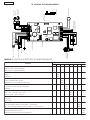 6
6
-
 7
7
-
 8
8
-
 9
9
-
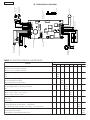 10
10
-
 11
11
-
 12
12
-
 13
13
-
 14
14
-
 15
15
-
 16
16
-
 17
17
-
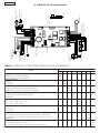 18
18
-
 19
19
-
 20
20
-
 21
21
-
 22
22
-
 23
23
-
 24
24


in altre lingue
- English: Genius GEO 03 Operating instructions
- français: Genius GEO 03 Mode d'emploi
- español: Genius GEO 03 Instrucciones de operación
- Deutsch: Genius GEO 03 Bedienungsanleitung
Documenti correlati
-
Genius LINX03 Istruzioni per l'uso
-
-
-
Genius JA487C Istruzioni per l'uso
-
-
-
-
-
-
