
KOS-L702
WIDE TOUCH SCREEN MONITOR 7 page 2-11
INSTRUCTION MANUAL
MONITEUR ECRAN LARGE TACTILE 7 page 12-21
MODE D’EMPLOI
WIDE TOUCH SCREEN MONITOR 7 Seite 22-31
BEDIENUNGSANLEITUNG
BREEDBEELD MONITOR MET AANRAAKSCHERM 7 blz 32-41
GEBRUIKSAANWIJZING
MONITOR TOUCH SCREEN PANORAMICO 7 pagina 42-51
ISTRUZIONI PER L’USO
MONITOR DE PANTALLA TÁCTIL PANORÁMICA 7 página 52-61
MANUAL DE INSTRUCCIONES
MONITOR DE ECRÃ LARGO DE TOQUE 7 página 62-71
MANUAL DE INSTRUÇÕES
7
© B64-3528-00/00 (WV)
Take the time to read through this instruction manual.
Familiarity with installation and operation procedures will help you obtain the best
performance from your new monitor.
For your records
Record the serial number, found on the back of the unit, in the spaces designated on the
warranty card, and in the space provided below. Refer to the model and serial numbers
whenever you call upon your Kenwood dealer for information or service on the product.
Model KOS-L702 Serial number
US Residence Only
Register Online
Register your Kenwood product at
www.Kenwoodusa.com

2
|
English
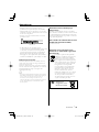
Safety precautions
2 CAUTION
To prevent damage to the machine, take
the following precautions:
• Do not install the unit in a spot exposed to direct
sunlight or excessive heat or humidity. Also avoid
places with too much dust or the possibility of
water splashing.
• When replacing a fuse, only use a new fuse with
the prescribed rating. Using a fuse with the wrong
rating may cause your unit to malfunction.
• Do not use your own screws. Use only the screws
provided. If you use the wrong screws, you could
damage the unit.
• You cannot view video pictures whilst the vehicle
is moving. To enjoy video pictures, find a safe
place to park and engage the parking brake.
2 WARNING
To prevent injury or fire, take the
following precautions:
• To prevent a short circuit, never put or leave any
metallic objects (such as coins or metal tools)
inside the unit.
• Do not watch or fix your eyes on the unit’s display
when you are driving for any extended period.
• Mounting and wiring this product requires
skills and experience. For safety’s sake, leave the
mounting and wiring work to professionals.
• Do not touch the liquid crystal fluid if the LCD
is damaged or broken due to shock. The liquid
crystal fluid may be dangerous to your health or
even fatal.
If the liquid crystal fluid from the LCD contacts
your body or clothing, wash it off with soap
immediately.
FCC WARNING
This equipment may generate or use radio frequency energy. Changes or modifications to this equipment may cause
harmful interference unless the modifications are expressly approved in the instruction manual. The user could lose the
authority to operate this equipment if an unauthorized change or modification is made.
NOTE
This Class B digital apparatus complies with Canadian ICES-003.

English
|
3
Notes
• If you experience problems during installation,
consult your Kenwood dealer.
• When you purchase optional accessories, check
with your Kenwood dealer to make sure that they
work with your model and in your area.
• If the unit fails to operate properly, press the Reset
button.
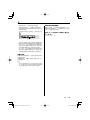
Reset button
• The illustrations of the display and the panel
appearing in this manual are examples used to
explain more clearly how the controls are used.
Therefore, what appears on the display in the
illustrations may differ from what appears on
the display on the actual equipment, and some
of the illustrations on the display may represent
something impossible in actual operation.
Cleaning the Unit
If the faceplate of this unit is stained, wipe it with a
dry soft cloth such as a silicon cloth.
If the faceplate is stained badly, wipe the stain off
with a cloth moistened with neutral cleaner, then
wipe it again with a clean soft dry cloth.
¤
• Applying spray cleaner directly to the unit may affect its
mechanical parts. Wiping the faceplate with a hard cloth
or using a volatile liquid such as thinner or alcohol may
scratch the surface or erases characters.
Screen brightness during low
temperatures
When the temperature of the unit falls such as
during winter, the liquid crystal panel’s screen will
become darker than usual. Normal brightness will
return after using the monitor for a while.
A/V controller you can control from the
KOS-L702 (As of March, 2007):
KOS-V500, KOS-V1000
Information on Disposal of Old Electrical
and Electronic Equipment (applicable for
EU countries that have adopted separate
waste collection systems)
Products with the symbol (crossed-out
wheeled bin) cannot be disposed as
household waste.
Old electrical and electronic equipment
should be recycled at a facility capable
of handling these items and their
waste byproducts. Contact your local
authority for details in locating a
recycle facility nearest to you. Proper
recycling and waste disposal will help
conserve resources whilst preventing
detrimental effects on our health and the
environment.

4
|
English
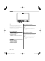
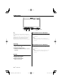
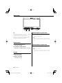
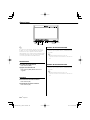
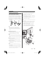
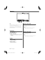
Operations
SRC/
PWR OFF
FUNC/
AV OUT
O
V.SEL/
V.OF F
MODE
Power
Turning ON the Power
Press the [SRC] button.
Turning OFF the Power
Press the [SRC] button for at least 1 second.
Switches the video source
Press the [V.SEL] button.
Each time the button is pressed, the video source
is changed.
⁄
• Refer to <Switches the video source> of <Basic
Operations> of the A/V controller's manual.
Volume
Increasing Volume:
Press the [5] button.
Decreasing Volume:
Press the [∞] button.
Auto Dimmer sensor
Switches the audio source
Press the [SRC] button.
Each time the button is pressed, the audio source
is changed.
⁄
• Refer to <Switches the audio source> of <Basic
Operations> of the A/V controller's manual.
⁄
Controlling of optional A/V controllers is possible by
touching the screen of this unit.
Functions which can be controlled vary depending
on the A/V controllers. Refer to the instruction
manual of the connected A/V controller for more
information.

English
|
5
Swithing the Display off mode
You can set the display off mode for the monitor.
Press the [V.SEL] button for at least 1 second.
Exit the Display off mode
Press any button.
Press the button other than the [5] and [∞]
buttons.
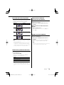
Switching Screen Mode
Press the [MODE] button.
Each time the button is pressed, the screen
mode switches as follows:
Display Setting
"Full"
Full picture mode
"Zoom"
Zoom picture mode
"Just" Justify picture mode
"Normal"
Normal picture mode
⁄
• Refer to <Monitor Setup> of the A/V controller's
manual.
• When you select the Menu, Easy Control screen,
or Navigation, the display is shown in the full-size
display mode automatically. The screen mode of these
displays cannot be changed.
Switches AV OUT source
Selects an AV source to be output at the "AV
OUTPUT" terminals.
Press the [FUNC] button for at least 1 second.
Each time the button is pressed for at least 1
second, the AV output is changed.
⁄
• Refer to <Switches AV OUT source> of <Basic
Operations> of the A/V controller's manual.
Switches the function screen
Switches to the control screens such as Source
Control Screen.
Press the [FUNC] button.
Each time the button is pressed, the function
control screen is changed.
Setting
Picture & Easy Control Panel
Source Control Screen
Picture Panel (OFF)
⁄
• Refer to <Switches the function screen> of <Basic
Operations> of the A/V controller's manual.

6
|
English
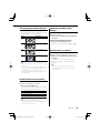
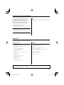
Accessories
1
..........1
2
..........1
3
..........5
4
..........1
(Ø4 × 12 mm)
5
..........1
6
..........1
7
..........1

English
|
7
1. To prevent short circuits, remove the key from
the ignition and disconnect the · terminal of
the battery.
2. Make the proper input and output cable
connections for each unit.
3. Connect the wiring harness connector to the
unit.
4. Install the unit in your car.
5. Reconnect the · terminal of the battery.
6. Press the reset button. (page 3)
2 WARNING
• To prevent shorting, disconnect the battery cable from
the negative terminal of the battery during installation.
• Be sure to firmly stabilise this product. Do not install it in
a location which is not stable.
• Follow the installation and wiring procedures described
in this manual. Improper wiring or modified installation
can not only result in malfunction or damage to the unit
but may also result in an accident.
• Do not install the unit in the following locations.
• A location which interferes with the operation of the air
bag system.
• A location which is not made of plastic.
\ Installing on leather, wood or cloth may damage the
surface.
• A location subject to direct sunlight, subject to the air
from the air conditioner, or subject to moisture or high
temperature.
\ This may cause deformation of the monitor unit.
• If you are not going to install the unit using the supplied
monitor stand, be sure to use a commercially available
monitor stand. (Mounting holes for such a stand are
located on the bottom of the monitor unit.)
¤
• If the fuse blows, first make sure that the wires have not
caused a short circuit, then replace the old fuse with one
with the same rating.
• Do not let unconnected wires or terminals touch metal
on the car or anything else conducting electricity. To
prevent short circuits do not remove the caps from
unused terminals or from the ends of the unconnected
wires.
• After the unit is installed, check whether the brake lamps,
blinkers, wipers, etc. on the car are working properly.
• Insulate unconnected wires with vinyl tape or other
similar material.
• Thoroughly wipe away oil and other dirt from the
installation surface.
Please avoid installation on uneven surfaces.
Installation Procedure

8
|
English
Connection
L
FM/AM
ANTENNA
FM/
AM
PRE
OUT
AV
IN 2
AV
IN 1
SUB REAR FRONT VIDEO VIDEOVIDEO
AV
OUT 2
AV
OUT 1
R-CAM
V-IN
MONITOR
POWER
MONITOR
I/F
POWER
Accessory 1
Monitor Unit
A/V controller (Optional accessory)
(KOS-V500)
MONITER POWER
Connect the wiring harness
referring to the instruction
manual of the connected A/V
controller.
MONITER POWER
Connect the wiring harness
referring to the instruction
manual of the connected A/V
controller.
A/V controller (Optional accessory)
(KOS-V1000)

English
|
9
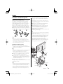
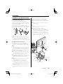
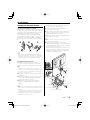
Installation
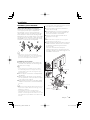
Installation for Monitor Unit
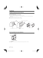
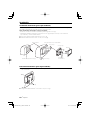
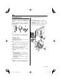
Installation location and cleaning
Select for installation a location where the stand
can be placed completely horizontal or where the
front edge of the support (petal-shaped part) can
be attached horizontally as shown in Figure A.
Do not install in locations where the entire support
is at a diagonal such as in Figure B or where the
monitor unit is facing down such as in Figure C.
A
B
C
¤
• Thoroughly wipe away and dust or grease from the
installation location using a cloth which has been soaked
in a neutral cleaning agent and wrung out. Attach the
stand after allowing the installation location to dry.
Installation for Monitor Unit
1 Install the shoe on the rear of the TV monitor
temporarily using the supplied hexagon wrench
(Accessary 4).
⁄
• When adjusting the fixing screw of the shoe, use the
hexagon wrench (Accessary 4) that came with the
product. Using other hexagon wrenches may damage
the screw.
2 Bend the stand support to conform to the shape
of the installation location.
3 Adjust the shape of the support so that there is
no rattling or gap when the stand is placed on
the support.
4 Peel off the protective strip from the double-
sided tape on the bottom of the stand and
securely attach the stand.
¤
• Do not attach the double-sided tape more than once or
touch the adhesive with your fingers as this will weaken
its adhesive strength.
• If the temperature of the surface of the installation
location is low, warm it up using a heater or other means
before attaching the stand. Low temperature may
weaken the adhesive strength of the tape.
• The supplied stand is specially intended for this product.
Do not use it with another monitor.
5 Secure the stand using the supplied tapping
screw (Accessory 3).
6 After attaching the stand, allow it to sit
undisturbed for 24 hours. Take care not to apply
any force to the stand during this time.
7 Insert the shoe of the monitor unit into the
bracket (Accessory 2).
¤
• Insert the shoe into the bracket (Accessory 2) as far as it
goes. (Fig. 1)
8 Adjust the height, horizontal and vertical angle
of the monitor unit, and securely tighten the
installation screws using the supplied hexagon
wrench (Accessary 4).
You can also adjust the monitor unit's forward
position by loosening the angle adjustment
knobs and adjusting the angle of the monitor
unit's installation stand.
Accessory 2
Accessory 3
Protective strip
Installation surface
Accessory 4
Shoe
Accessory 4
Tighten
Loosen
Fig. 1

10
|
English
Installation
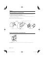
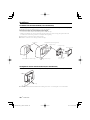
Installation for Monitor Unit (For Headrest)
Mounting and wiring this product requires skills and experience. For safety's sake, leave the mounting and
wiring work to professionals.
Before mounting the monitor to the headrest:
• Perform the required external connections first (Accessory 1).
• Using the supplied paper template (Accessory 7), mark the area to be cut out of the headrest, then
carefully cut it.
1 Connect Monitor and system cord (Accessory 1).
2 Install the monitor unit in the bracket (Accessory 5).
Headrest
Accessory 5
Accessory 1
Screws (not supplied)
Monitor Unit
Installation plate (not supplied)
Paper template (Accessory 7)
Accessory 1
Removing the Monitor Unit (For Headrest)
1 Insert the removal tool (Accessory 6) deeply into the slots on each side, as shown.
Accessory 6
2 Pull the monitor unit all the way out with your hands, being careful not to drop it.

English
|
11
Troubleshooting Guide
What might seem to be a malfunction in your unit
may just be the result of slight misoperation or
miswiring. Before calling service, first check the
following table for possible problems.
? The power does not turn ON.
✔ The motor is not attached to the bracket securely.
☞ Attach the motor to the bracket until it clicks.
? Nothing happens when the buttons are pressed.
✔ The computer chip in the unit is not functioning
normally.
☞ Press the reset button on the unit (page 3).
Monitor Section
Screen size
: 6.95 inches wide
156.2(W) × 82.4(H) × 176.0(Diagonal) mm
6-1/8(W) × 3-1/4(H) inches
Display system
: Transparent TN LCD panel
Drive system
: TFT active matrix system
Number of pixels
: 336,960 pixels (480 H × 234 V × RGB)
Effective pixels
: 99.99%
Pixel arrangement
: RGB striped arrangement
Back lighting
: Cold cathode tube
Colour system
: NTSC/ PAL
Analog RGB input (13P)
: 0.7 Vp-p/ 75 Ω
Specifications subject to change without notice.
General
Operating voltage
: 14.4 V DC (11 - 16 V)
Current consumption
: 1.5 A
Operational temperature range
: –10°C to +60°C
Storage temperature range
: –20°C to +85°C
Dimensions (W × H × D)
: 177 × 122 × 34 mm
7 × 4-6/8 × 1-5/16 inch
Weight
: 460 g (1.01 lbs)
Specifications
Although the effective pixels for the liquid crystal panel is given as 99.99% or more, 0.01% of pixels may not light or may
light incorrectly.
⁄
• Refer to the instruction manual of the connected A/C
controller for troubleshooting on the operation.

12
|
Français
Précautions de sécurité
2ATTENTION
Pour éviter tout dommage à l’appareil,
veuillez prendre les précautions
suivantes:
• N’installez pas l’appareil dans un endroit exposé
directement à la lumière du soleil, à une chaleur
excessive ou à l’humidité. Evitez également
les endroits trop poussiéreux ou exposés aux
éclaboussures.
• Lors du remplacement d’un fusible, utilisez
seulement un fusible neuf du même calibre.
L’utilisation d’un fusible de calibre différent peut
entraîner un mauvais fonctionnement de votre
appareil.
• N'utilisez pas vos propres vis. N'utilisez que les vis
fournies. L’utilisation de vis incorrectes pourrait
endommager l’appareil.
• Vous ne pouvez pas visionner des images vidéo
pendant que le véhicule est en mouvement. Pour
profiter des images vidéo, trouvez un endroit sûr
où stationner et mettez le frein à main.
2Avertissement
Pour éviter toute blessure et/ou incendie,
veuillez prendre les précautions
suivantes :
• Pour éviter les court-circuits, ne jamais mettre ou
laisser d’objets métalliques (comme une pièce
de monnaie ou un outil en métal) à l’intérieur de
l’appareil.
• Ne regardez pas l'affichage de l'appareil de
manière prolongée lorsque vous conduisez.
• Le montage et le câblage de ce produit
nécessitent des compétences et de l'expérience.
Pour des raisons de sécurité, laissez un
professionnel effectuer le travail de montage et de
câblage.
• Ne touchez pas le fluide à cristaux liquides si
l’écran LCD est endommagé ou cassé à la suite
d’un choc. Le fluide à cristaux liquides peut être
dangereux pour votre santé ou même mortel.
Si le fluide à cristaux liquides de l’écran LCD entre
en contact avec votre peau ou vos vêtements,
lavez-les immédiatement avec du savon.
REMARQUE
Cet appareil numérique de la classe B est conforme à la norme NMB-003 du Canada.

Français
|
13
Remarques
• Si vous rencontrez des problèmes pendant
l’installation, consultez votre revendeur Kenwood.
• Lorsque vous achetez des accessoires en option,
vérifiez auprès de votre revendeur Kenwood que
ces accessoires fonctionnent avec votre modèle
dans votre région.
• Si l’appareil ne fonctionne pas correctement,
appuyez sur la touche de réinitialisation.
Touche de réinitialisation
• Les illustrations de l’affichage et du panneau
apparaissant dans ce manuel sont des exemples
utilisés pour expliquer avec plus de clarté
comment les commandes sont utilisées. Il est
donc possible que les illustrations d’affichage
puissent être différentes de ce qui est réellement
affiché sur l’appareil, et aussi que certaines
illustrations représentent des choses impossibles à
réaliser en cours de fonctionnement.
Nettoyage de l’appareil
Si la façade de l’appareil est sale, essuyez-la avec
un chiffon sec et doux, par exemple un chiffon au
silicone.
Si le panneau avant est très taché, essuyez-le avec
un chiffon imbibé d’un produit de nettoyage neutre
et essuyez ensuite toute trace de ce produit.
¤
• La pulvérisation directe de produit de nettoyage sur
l’appareil risque d’affecter les pièces mécaniques. Le fait
d’essuyer la façade avec un chiffon rugueux ou d’utiliser
un liquide volatil tel qu’un solvant ou de l’alcool peut
égratigner la surface ou effacer les caractères.
Luminosité de l’écran lorsque la
température est basse
Lorsque la température de l’appareil descend très
bas pendant l’hiver, l’écran à cristaux liquides du
panneau deviendra plus sombre que d’habitude.
La luminosité normale se rétablira après que le
moniteur ait fonctionné pendant un moment.
Contrôleur A/V que vous pouvez
commander à partir du KOS-L702 (à
partir de mars 2007):
KOS-V500, KOS-V1000
Information sur l’élimination des anciens
équipements électriques et électroniques
(applicable dans les pays de l’Union
Européenne qui ont adopté des systèmes
de collecte sélective)
Les produits sur lesquels le pictogramme
(poubelle barrée) est apposé ne peuvent
pas être éliminés comme ordures
ménagères.
Les anciens équipements électriques et
électroniques doivent être recyclés sur
des sites capables de traiter ces produits
et leurs déchets. Contactez vos autorités
locales pour connaître le site de recyclage
le plus proche. Un recyclage adapté
et l’élimination des déchets aideront
à conserver les ressources et à nous
préserver des leurs effets nocifs sur notre
santé et sur l’environnement.

14
|
Français
Fonctionnement
SRC/
PWR OFF
FUNC/
AV OUT
O
V.SEL/
V.OF F
MODE
Alimentation
Allumer l’alimentation
Appuyez sur la touche [SRC].
Eteindre l’alimentation
Appuyez sur la touche [SRC] pendant au
moins 1 seconde.
Pour changer la source vidéo
Appuyez sur la touche [V.SEL].
À chaque fois que l’on appuie sur la touche, la
source vidéo change.
⁄
• Veuillez vous reporter à la section <Change la source
vidéo> du chapitre <Fonctionnement de base> du
manuel du contrôleur A/V.
Volume
Augmentation du volume :
Appuyez sur la touche [5].
Diminution du volume :
Appuyez sur la touche [∞].
Capteur de luminosité
auto
Pour changer la source audio
Appuyez sur la touche [SRC].
À chaque fois que l’on appuie sur la touche, la
source audio change.
⁄
• Veuillez vous reporter à la section <Change la source
audio> du chapitre <Fonctionnement de base> du
manuel du contrôleur A/V.
⁄
Il est possible de commander les contrôleurs A/V
optionnels en touchant l'écran de cette unité.
Les fonctions pouvant êtres contrôlées varient selon
le contrôleur A/V. Veuillez vous reporter au manuel
d'instructions du contrôleur A/V connecté pour de
plus amples informations.

Français
|
15
Passer en mode d'affichage
désactivé
Vous pouvez désactiver l'affichage du moniteur.
Appuyez sur la touche [V.SEL] pendant au
moins 1 seconde.
Quitter le mode d'affichage désactivé
Appuyez sur n’importe quelle touche.
N'appuyez pas sur les touches [5] et [∞].
Commutation du mode d'écran
Appuyez sur la touche [MODE].
A chaque fois que l’on appuie sur la touche, le
mode d’écran commute comme suit :
Affichage Réglage
"Full"
Mode d'affichage plein écran
"Zoom"
Mode d'image avec zoom
"Just" Justifier le mode d'image
"Normal"
Mode d'image normale
⁄
• Veuillez vous reporter à la section <Configuration du
moniteur> du manuel du contrôleur A/V.
• Quand vous sélectionnez le menu, l'écran de
commande facile "Easy", ou celui de navigation,
l'affichage apparaît automatiquement en mode plein
écran. Le mode d'écran de ces affichages ne peut pas
être modifié.
Pour changer la source AV OUT
Sélectionne la source AV qui doit être émise par
les bornes "AV OUTPUT".
Appuyez sur la touche [FUNC] pendant au
moins 1 seconde.
À chaque fois que vous appuyez sur cette
touche pendant au moins 1 seconde, la sortie AV
change.
⁄
• Veuillez vous reporter à la section <Change la source
AV OUT> du chapitre <Fonctionnement de base> du
manuel du contrôleur A/V.
Pour changer l'écran de fonction
Pour passer aux écrans de commande tels que
l'écran de commande de la source.
Appuyez sur la touche [FUNC].
À chaque fois que l’on appuie sur cette touche,
l'écran de commande de fonction change.
Réglage
Image et panneau de commande facile "Easy"
Écran de commande de la source
Panneau d'image (OFF)
⁄
• Veuillez vous reporter à la section <Change l'écran de
fonction> du chapitre <Fonctionnement de base> du
manuel du contrôleur A/V.

16
|
Français
Accessoire
1
..........1
2
..........1
3
..........5
4
..........1
(Ø4 × 12 mm)
5
..........1
6
..........1
7
..........1

Français
|
17
1. Afin d’empêcher tout court-circuit, retirez la clé
de contact et déconnectez la borne · de la
batterie.
2. Effectuez correctement les connexions de câble
d’entrée et de sortie pour chaque appareil.
3. Connectez le connecteur du faisceau de câbles à
l’appareil.
4. Installez l’appareil dans votre voiture.
5. Reconnectez la borne · la batterie.
6. Appuyez sur la touche de réinitialisation. (page
13)
2 AVERTISSEMENT
• Afin d’éviter tout court-circuit, déconnectez le câble de
batterie de la borne négative de la batterie pendant
l’installation.
• Assurez-vous de stabiliser fermement ce produit. Ne
l’installez pas dans un emplacement instable.
• Suivez les procédures d’installation et de câblage
décrites dans ce manuel. Un câblage incorrect ou
une modification de l’installation peut non seulement
entraîner un dysfonctionnement ou des dommages à
l’appareil, mais peuvent également causer un accident.
• N’installez pas l’appareil dans les endroits suivants.
• Un emplacement qui interfère avec le fonctionnement
d’un système d’air bag.
• Un emplacement qui n’est pas fait de plastique.
\ L'installation sur du cuir, du bois ou du tissu risque
d'en endommager la surface.
• Un endroit exposé à la lumière directe du soleil, à un
courant d’air conditionné, à de l’humidité ou a des
températures élevées.
\ Le moniteur risque de subir une déformation.
• Si vous installez l’appareil sur un autre support de
moniteur que celui fourni, assurez-vous d’utiliser un
support de moniteur disponible dans le commerce. (Des
trous de montage pour un tel support sont situés en bas
du moniteur.)
¤
• Si le fusible grille, assurez-vous d’abord que les fils n’ont
pas causé de court-circuit, puis remplacez le fusible
usagé par un autre du même calibre.
• Ne laissez pas de fils ou de bornes non-connectés
toucher le métal de la voiture ou tout autre élément
conducteur d’électricité. Afin d’empêcher tout court-
circuit, ne retirez pas les capuchons des bornes non-
utilisées ou de l’extrémité des câbles non-connectés.
• Après avoir installé l’appareil, vérifiez si les lampes de
frein, les indicateurs, les clignotants, etc. de la voiture
fonctionnent correctement.
• Isolez les câbles non-connectés avec un ruban de vinyle
ou d’un autre matériel similaire.
• Essuyez avec soin la graisse ou la saleté de la surface
d’installation.
Veuillez éviter d’installer l’appareil sur des surfaces
inégales.
Procédure d’installation

18
|
Français
Connexion
L
FM/AM
ANTENNA
FM/
AM
PRE
OUT
AV
IN 2
AV
IN 1
SUB REAR FRONT VIDEO VIDEOVIDEO
AV
OUT 2
AV
OUT 1
R-CAM
V-IN
MONITOR
POWER
MONITOR
I/F
POWER
Accessoire 1
Unité moniteur
Contrôleur A/V (accessoire optionnel)
(KOS-V500)
RACCORDEMENT ÉLECTRIQUE
DU MONITEUR
Connectez le faisceau de câblage
en vous reportant au manuel
d'instructions du contrôleur A/V
connecté.
RACCORDEMENT ÉLECTRIQUE
DU MONITEUR
Connectez le faisceau de
câblage en vous reportant
au manuel d'instructions du
contrôleur A/V connecté.
Contrôleur A/V (accessoire optionnel)
(KOS-V1000)

Français
|
19
Installation
Installation pour le moniteur
Emplacement d’installation et nettoyage
Sélectionnez pour l’installation un emplacement
où le support peut être placé complètement
à l’horizontale ou encore où le bord avant du
support (partie en forme de pédale) peut être fixé
horizontalement comme montré sur la figure A.
N’installez pas dans des emplacements où la totalité
du support serait en diagonale, comme montré sur
la figure B, ou encore où le moniteur serait orienté
vers le bas, comme montré sur la figure C.
A
B
C
¤
• Nettoyez avec soin la poussière et la graisse de
l’emplacement d’installation avec un tissu trempé dans
une solution détergente neutre et essoré. Fixer le socle
après avoir séché l’emplacement d’installation.
Installation pour le moniteur
1 Installez temporairement le sabot à l'arrière du
moniteur TV en utilisant la clé mâle hexagonale
fournie (Accessoire 4).
⁄
• Lors du réglage de la vis de fixation du sabot, utilisez
la clé mâle hexagonale (Accessoire 4) fournie avec le
produit. L'utilisation d'une autre clé hexagonale risque
d'endommager la vis.
2 Plier le support selon la forme de l’emplacement
d’installation.
3 Ajuster la forme du support de sorte qu’il n’y a
pas de crépitement ou un espace libre lorsque le
socle est placé sur le support.
4 Enlever la bande de protection du ruban adhésif
double face au fond du socle et fixer fermement
le socle.
¤
• Ne pas fixer le ruban adhésif double face plusieurs fois et
ne pas toucher le ruban adhésif avec les doigts, car cela
affaiblit la force adhésive.
• Si la température à la surface de l’emplacement
d’installation est trop basse, la réchauffer à l’aide d’un
radiateur ou un autre appareil avant de fixer le socle. Une
basse température risque d’affaiblir la force adhésive de
la bande.
• Le montant fourni est spécialement destiné à ce produit.
Ne pas l’utiliser avec un autre téléviseur.
5 Fixer le montant à l’aide de la vis taraudeuse
fournie (Accessoire 3).
6 Après la fixation du socle, le laisser pendant 24
heures. Faire attention à ne pas appliquer une
force sur le montant à ce moment-là.
7 Insérez le sabot de l'unité moniteur dans le
support (Accessoire 2).
¤
• Insérez le sabot dans le support (Accessoire 2) aussi
profondément que possible. (Fig. 1)
8 Réglez la hauteur, l'angle horizontal et vertical de
l'unité moniteur et serrez bien les vis de fixation
en utilisant la clé mâle hexagonale fournie
(Accessoire 4).
La position en avant du moniteur peut
également être réglée en desserrant le bouton
de réglage d’angle et en ajustant l’angle du socle
d’installation du moniteur.
Accessoire 2
Accessoire 3
Bande de protection
Surface d’installation
Accessoire 4
Sabot
Accessoire 4
Serrer
Desserrer
Fig. 1

20
|
Français
Installation
Installation du moniteur (pour appui-tête)
Le montage et le câblage de ce produit nécessite des compétences et de l'expérience. Pour des raisons de
sécurité, laissez un professionnel effectuer le travail de montage et de câblage.
Avant de monter le moniteur sur l'appui-tête :
• Effectuez d'abord les connexions nécessaires (Accessoire 1).
• À l'aide du modèle papier fourni (Accessoire 7), marquez la zone à couper de l'appui-tête, puis découpez-
la avec soin.
1 Connectez le câble du moniteur et du système (Accessoire 1).
2 Installez l'unité du moniteur dans le support (Accessoire 5).
Appui-tête
Accessoire 5
Accessoire 1
Vis (non fournies)
Unité moniteur
Plaque d'installation (non fournie)
Modèle en papier (Accessoire 7)
Accessoire 1
Démontage du moniteur (Pour appui-tête)
1 Insérez profondément l'outil de démontage (Accessoire 6) dans les rainures situées de chaque côté,
comme indiqué.
Accessoire 6
2 Tirez entièrement le moniteur avec les mains, en faisant attention à ne pas le laisser tomber.
La pagina si sta caricando...
La pagina si sta caricando...
La pagina si sta caricando...
La pagina si sta caricando...
La pagina si sta caricando...
La pagina si sta caricando...
La pagina si sta caricando...
La pagina si sta caricando...
La pagina si sta caricando...
La pagina si sta caricando...
La pagina si sta caricando...
La pagina si sta caricando...
La pagina si sta caricando...
La pagina si sta caricando...
La pagina si sta caricando...
La pagina si sta caricando...
La pagina si sta caricando...
La pagina si sta caricando...
La pagina si sta caricando...
La pagina si sta caricando...
La pagina si sta caricando...
La pagina si sta caricando...
La pagina si sta caricando...
La pagina si sta caricando...
La pagina si sta caricando...
La pagina si sta caricando...
La pagina si sta caricando...
La pagina si sta caricando...
La pagina si sta caricando...
La pagina si sta caricando...
La pagina si sta caricando...
La pagina si sta caricando...
La pagina si sta caricando...
La pagina si sta caricando...
La pagina si sta caricando...
La pagina si sta caricando...
La pagina si sta caricando...
La pagina si sta caricando...
La pagina si sta caricando...
La pagina si sta caricando...
La pagina si sta caricando...
La pagina si sta caricando...
La pagina si sta caricando...
La pagina si sta caricando...
La pagina si sta caricando...
La pagina si sta caricando...
La pagina si sta caricando...
La pagina si sta caricando...
La pagina si sta caricando...
La pagina si sta caricando...
La pagina si sta caricando...
La pagina si sta caricando...
La pagina si sta caricando...
La pagina si sta caricando...
La pagina si sta caricando...
La pagina si sta caricando...
La pagina si sta caricando...
La pagina si sta caricando...
La pagina si sta caricando...
La pagina si sta caricando...
La pagina si sta caricando...
La pagina si sta caricando...
La pagina si sta caricando...
La pagina si sta caricando...
-
 1
1
-
 2
2
-
 3
3
-
 4
4
-
 5
5
-
 6
6
-
 7
7
-
 8
8
-
 9
9
-
 10
10
-
 11
11
-
 12
12
-
 13
13
-
 14
14
-
 15
15
-
 16
16
-
 17
17
-
 18
18
-
 19
19
-
 20
20
-
 21
21
-
 22
22
-
 23
23
-
 24
24
-
 25
25
-
 26
26
-
 27
27
-
 28
28
-
 29
29
-
 30
30
-
 31
31
-
 32
32
-
 33
33
-
 34
34
-
 35
35
-
 36
36
-
 37
37
-
 38
38
-
 39
39
-
 40
40
-
 41
41
-
 42
42
-
 43
43
-
 44
44
-
 45
45
-
 46
46
-
 47
47
-
 48
48
-
 49
49
-
 50
50
-
 51
51
-
 52
52
-
 53
53
-
 54
54
-
 55
55
-
 56
56
-
 57
57
-
 58
58
-
 59
59
-
 60
60
-
 61
61
-
 62
62
-
 63
63
-
 64
64
-
 65
65
-
 66
66
-
 67
67
-
 68
68
-
 69
69
-
 70
70
-
 71
71
-
 72
72
-
 73
73
-
 74
74
-
 75
75
-
 76
76
-
 77
77
-
 78
78
-
 79
79
-
 80
80
-
 81
81
-
 82
82
-
 83
83
-
 84
84


Kenwood KOS-L702 Manuale del proprietario
- Tipo
- Manuale del proprietario
- Questo manuale è adatto anche per
in altre lingue
- English: Kenwood KOS-L702 Owner's manual
- français: Kenwood KOS-L702 Le manuel du propriétaire
- español: Kenwood KOS-L702 El manual del propietario
- Deutsch: Kenwood KOS-L702 Bedienungsanleitung
- Nederlands: Kenwood KOS-L702 de handleiding
- português: Kenwood KOS-L702 Manual do proprietário
Documenti correlati
-
Kenwood KOS-L432 Manuale utente
-
-
Kenwood KOS-CV100 Manuale del proprietario
-
-
Kenwood KTC-D500E Manuale del proprietario
-
-
-
Kenwood KDV-S250P Manuale utente
-
-
