Harman Stove Company Magnum Stoker Manuale utente
- Categoria
- Stufe
- Tipo
- Manuale utente
Questo manuale è adatto anche per

MGMR13
SAFETY NOTICE
PLEASE READ THIS ENTIRE MANUAL BEFORE YOU INSTALL AND USE YOUR NEW ROOM HEATER. FAILURE TO
FOLLOW INSTRUCTIONS MAY RESULT IN PROPERTY DAMAGE, BODILY INJURY, OR EVEN DEATH.
FOR USE IN THE U.S. AND CANADA.
IF THIS HARMAN STOVE IS NOT PROPERLY INSTALLED, A HOUSEFIRE MAY RESULT. FOR YOUR SAFETY, FOLLOW
INSTALLATION DIRECTIONS.
CONTACT LOCAL BUILDING OR FIRE OFFICIALS ABOUT RESTRICTIONSAND INSTALLATION INSPECTION
REQUIREMENTS IN YOUR AREA.
CONTACT YOUR LOCAL AUTHORITY (SUCH AS MUNICIPAL BUILDING DEPARTMENT, FIRE DEPARTMENT, FIRE
PREVENTION BUREAU, ETC.) TO DETERMINE THE NEED FOR A PERMIT.
CETTE GUIDE D'UTILISATION EST DISPONIBLE EN FRANCAIS. CHEZ VOTRE CONCESSIONNAIRE DE HARMAN STOVE
COMPANY.
SAVE THESE INSTRUCTIONS.
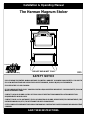
The Harman Magnum Stoker
Installation & Operating Manual
R15
DO NOT BURN WET COAL.
Tested by:
OMNI-TEST Laboratory

2
DO NOT BURN WET COAL
INDEX
Introduction 3
Warnings 3
Packing List 5
Assembly 6
Installation 9
Verti-Flow Stoker Control 10
Operation 14
Maintenance 15
Trouble-Shooting 17
Wiring Diagram 19
Feeder Parts 20
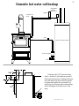
Domestic Hot Water Coil 21
Hot Air Option 22
Warranty 23

3
DO NOT BURN WET COAL
WARNINGS
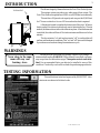
INTRODUCTION
This all new design by Harman features the Verti-Flow Stoker System.
This unique system provides a very wide range of heat output. The
Verti-Flow Stoker can operate from 5000 to over 85,000 btu's automatically.
This unit has a 100 pound coal capacity and can provide 85,000 btu's
for 17 hours or stretch out to over 100 hours when less heat is required.
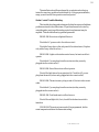
A thermostat is used to regulate the heat output of the stove. When no
heat is needed, the stoker stops and only runs to maintain the fire. If heat is
needed, the thermostat can turn on the stoker at any time. After the thermostat
is satisfied, the stoker will turn off for twelve minutes and then run for four
minutes.
The four minutes "on" and twelve minutes "off" is a setting that will
perform well under most conditions. This "on" and "off" time can be changed
to provide more or less heat during the maintenance cycle.
This unit must be connected to a chimney capable of providing a .04
minimum draft reading. WARNING!! If the chimney has no draft, coal gases
may escape from the unit and stovepipe. These gases are toxic and can be
fatal. It is recommended that a gas detector be installed to warn of this
condition. Check with your local stove dealer for purchasing a gas detector.
100 LBS.
COAL
THERMOSTAT
Never sleep in the same
room with any coal
burning stove.
TESTING INFORMATION
This unit has been tested and approved by OMNI-TEST Labo-
ratories in accordance to the listed codes.

4
DO NOT BURN WET COAL
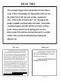
READ THIS
Always empty hopper when not burning for more than a
week. When left standing for long periods with wet coal,
the pusher block will rust and corrode, causing it to
seize. If the stoker is then turned "on", damage to the
pusher assembly and feed motor will result. This will be
considered neglect and will void the warranty on those
parts. Always check to see if moving parts are free
before using if the unit has not been burned for a period
of time. This can best be determined by shaking the
adjuster rod.
Freshly delivered coal is watered down
to eliminate dust when loading and unloading.
Wet rice coal does not flow as well as damp or
dry coal. We do not recommend burning wet
coal, however, we realize if it's the only coal you
have it is better to burn it than freeze. If you
must burn wet coal, the feed rate must be in-
creased in order to get the same size fire. As the
wet coal in the hopper dries out, the feed rate
must be decreased. If you don’t, the feeder will
over-fire the stove and waste coal. Doing this
once or twice a year will not damage your stove
as long as it is hot and burning. The damage is
caused when the hopper has wet coal in it when
the stove is cold.
This will cause rust and corro-
sion and it is totally the operator’s fault.
Usually after the coal dries for three
or four days, depending on conditions, it will
flow very well and feed properly. Feed rate
will be the same as dry coal.
Damp coal also should not be left in
the hopper of a cold stove.
Damp Coal
Wet Coal

5
DO NOT BURN WET COAL
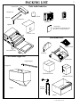
Parts inside stove
Parts inside hopper box
grate holder
firebricks
combustion blower
distribution blower
ash pan
hopper lid
hopper
hopper support
Inside bag
(2) terminals for thermostat wire
(4) 8-32 x 1/2 screws and nuts
control box
thermostat
motor cover
main feeder body
adjuster
adjuster tube
adjuster rod
wing nut
(2) grate inserts
scraper
assembly
Pusher block
Parts inside feeder box
PACKING LIST
Restricter Plate

6
DO NOT BURN WET COAL
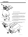
ASSEMBLY
adjuster tube
wing nut
adjuster
fig 2
feed indicator
dust tray
fig 1
First, a note to you, the customer.
This section on Assembly is in the manual for your information
should you ever need to move your unit and to help you under-
stand how each part is installed.
It is not intended by Harman Stove Company that you
assemble this unit. This job is to be performed by your Harman
Dealer who has been taught how to assemble and explain the
operation of your new stoker to you.
Your dealer will also take a draft reading with the stoker
burning. This reading must be recorded on the warranty coupon in
order to activate your warranty.
The assembly and set-up are free. However, we do not
wish to imply that delivery and installation are free.
slot
adjuster rod
Pusher
block

7
DO NOT BURN WET COAL
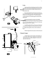
Control Box
Small blower
Large blower
thermostat
fig 3
fig 4
gasket
Feeder
Begin assembly by sliding the pusher block with the
adjuster rod from the front through the slot shown in fig.1.
Be sure the pusher block is turned with the bolt hole to
feed indicator side.
Next, hold pusher block in the most rearward posi-
tion and slide the adjuster tube over the adjuster rod until it
bottoms out on the pusher block. Thread the adjuster
over the adjuster rod. Thread wing nut on the end of the
adjuster rod.
Make sure the gasket is in place on the feeder
opening on the rear of the unit, as shown in fig 3. Insert the
stoker into the opening in the rear of the unit. Bolt fast and
tighten with (2) 5/16 X 1 1/4 bolts.
Install the smaller of the two blowers on the bottom
of the feeder by sliding it into the bracket as far as it will
go. Install restricter plate on blower as shown below in
Fig. 4.
Slide the larger blower into place on the bottom rear
Restricter Plate
Control Box
Blowers
Cleanout Scraper
Install scraper as shown below with locking nut
on each side of the scraper. Tighten nuts when in the
rear most position to assure alignment. Cycle rod in
and out to clean unit.
lock nut
scraper

8
DO NOT BURN WET COAL
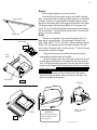
hopper support
slotted holes
Gasket
fig 7
Grate insert
fig 6
Grate holder
Grate
angle
.
fig 5
Be sure the grate holder
is centered and back as
far as possible.
IMPORTANT
Install firebricks
as Shown
The grate holder must be installed through the top door
opening after the feeder has been installed.
Locate the flange at the rear of the grate holder into the slot
on the feeder as shown below. Bolt the front end down with the
1/4 x 20 Allen bolt and nut provided. The rear end will be locked
in place by the flange. Before tightening the bolt be sure the grate
holder is back as far as possible and centered side to side on the
feeder opening.
Install grate inserts as shown at left. Divide the spaces
between the inserts equally and be sure they are not tight. The
spaces are needed for expansion.
Hopper
Install hopper support on top rear of stoker.
Note that bolt holes in hopper support are slotted for adjust-
ment. Insert small end of hopper into the hopper slot on the feeder
as shown. Push top of hopper under the hopper support, causing
the slot on the bottom side of the support to hook onto the hopper.
The hopper support will spring up slightly for the hopper to go
under. If you have difficulty getting the hopper under, adjustment
may be necessary. Use slotted holes shown at left. Now the feed
motor cover can be installed.
Grate
The grate is composed of four pieces:the grate holder, (2)
grate inserts, and grate angle. The grate angle is bolted to the
grate holder with (2) 3/8 X 1 1/4 bolts. Before installing the grate
holder, 3/8" round gasket must be checked in the groove on the
botton side of the grate holder, as shown in fig. 7. Check to be sure
the gasket has not been damaged.
firebricks

9
DO NOT BURN WET COAL
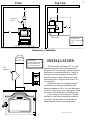
minimum 4"
34"
34"
18"
barometric
damper
draft
adjustment
8"
8"
16"
Use only U.L. approved floor
board
IMPORTANT
Front
Top View
Clearance to Combustibles
INSTALLATION
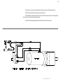
Take draft reading between the
barometric damper and the
stove. Do this on pilot mode.
IMPORTANT
Place the stoker a minimum of 4" to a com-
bustible wall from the rear of the hopper and a
minimum of 34" from the sides. The stove should
be placed on a noncombustible floor. Install a 6"
stove pipe from flue opening to chimney with a
barometric damper. Secure all pipe joints with
sheet metal screws. Plug power cord into a 120
volt receptacle.
Refer to the section on operation to light a
fire. With the stove burning and stabilized set
barometric damper at .04 to .06 on the draft meter.
We do not expect you to own a draft meter. There-
fore, have your dealer do set-up and fine tuning.
If your chimney will not produce .04 on the
draft meter, a draft inducer should be installed by
your dealer. The draft inducer will provide the
additional draft needed for proper operation.

10
DO NOT BURN WET COAL
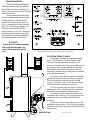
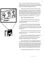
Timer settings shown above will perform well in most cases.
Verti-Flow Stoker Control
This section describes the features and opera-
tions of The Harman Verti-Flow Stoker Control.
The timers are adjustable from 0 minutes to 15
minutes in 1 minute steps. There are red lights on the
front panel to show proper operation of the timer.
One indicator shows power is applied to the unit.
The other 3 indicators show when power is available
at the adjacent receptacle.
The stoker control will be mounted on the side
panel of the feeder directly below the coal hopper.
The three receptacles and switch will be facing
forward. The power cord, 3 AMP fuse access port
and the thermostat connections to the rear.
The top receptacle provides power to the coal
feeder motor. Thus, the plug from the coal feeder
motor should be inserted into this receptacle.
The center receptacle provides power for the
combustion blower motor. Thus, the plug from the
combustion blower should be inserted into this
receptacle.
The bottom receptacle provides power for the
distribution blower motor. Thus, this final receptacle
should be connected to the plug from the distribution
blower motor.
Restricter Plate
Fine Tuning Draft
With fire burning and stablized
take draft reading in flue pipe and note
the reading. Next take a reading in the
fire box by removing the bolt in the front
center of the unit.
While watching the draft meter,
close the restricter plate on the combus-
tion blower slowly, until the needle
reads about the same as it did on the
flue. An example would be a flue read-
ing of .05 and a firebox reading of .02.
Close the restricter plate until the
firebox reading is .04 to.05. Closing the
restricter plate will reduce the positive
pressure from the blower and increase
the negative pressure in the firebox.
WARNING!
If draft is at .00, carbon monoxide
will escape into the room. Too
much carbon monoxide can kill
you.

11
DO NOT BURN WET COAL
of the stove. NOTE: The bolt holes on the blowers are not
used.
Install the control box on mounting pad provided on the
side of the stoker with (4) #8-32 bolts. NOTE: The recep-
tacles go toward the front.
Plug the gear motor into the top, the small combustion
blower into the middle, and the large distribution blower into
the bottom receptacle on the control box as shown. More on
the control later.
The thermostat connections on the back panel of the
Stoker Control are .25 inch male quick connect terminals.
The mating connectors (supplied) should be .25 inch female
quick connector terminals. The wire should be no smaller
than 22 gauge.
The thermostat connections should only be connected
across the thermostat switch inside the thermostat unit. This
switch is the type which opens (turns off) when the set point
temperature is reached, and closes (turns on) when the room
temperature falls below the temperature. (This is the type
supplied with the unit.)
The AC power cord should be the last connection
made. The power cord should be plugged into a 115 AC
volt 60 hertz wall outlet, which has proper grounding avail-
able. This 115 AC volt wall outlet should also be capable of
handling 3 amps of current because this is the maximum
amperage this unit will draw.
Basic Theory of Operation
After the stoker control is properly installed, operation
of the stove may begin. The stove operation is controlled
from the thermostat. This means if the room temperature is
cooler than the temperature set on the thermostat, the stove
will begin operation with the stoker control in the inactive
state. Once the room temperature reaches the thermostat set
point temperature, the combustion blower and coal feeder
will turn off, but the distribution blower will still operate. At
this point, the stoker control has taken control of the stove's
Place thermostat in a central location.
Do not place it in an isolated room with
poor air circulation

12
DO NOT BURN WET COAL
operation. The timer will continue to control the stove until
the room temperature drops below the thermostat set point
temperature. At this time, the stove will operate constantly
until the room temperature reaches the thermostat set point
again and the cycle repeats.
It should be noted that the timer adjustments do have a
0 minute position. The default conditions for these adjust-
ments set for 0 minutes are as follows: "on time" 0," off time"
0 unit will run constantly; "on time" greater than O," off time"
0, unit will run constantly; "on time" 0," off time" greater than
0, unit will cycle on and off with the "off" time being the
controlling timer. It is not recommended that the 0 minute
time be used on any of the adjustments. The 0 minute time is
an invalid condition on the stoker control.
When the stoker control first takes control in the
maintenance cycle, two timers are activated, the "distribution
blower" timer and the unit "off" timer.
The "distribution blower" timer is an off delay timer.
This means after the combustion blower and coal feeder turn
off the distribution blower will operate for a programmed
period of time before turning off. The stoker control timing
range for this function is 0 minutes to 15 minutes.
The purpose of having the off delay timer on to distri-
bution blower is to exhaust the excess heat in the stove that
is inherent after the combustion blower and coal feeder turn
off. For this reason, it is not recommended that a 0 time
setting be used. This will minimize any possibility of over-
heating the stove.
The other timer, which begins when the stoker control
first takes control, is the "off" timer. This function of the
stoker control is adjustable from 0 minutes to 15 minutes.
Programming this timer with a valve lets the stoker timer
know how long to keep the combustion blower and the coal
feeder turned off between maintenance cycles.
Once the off timer has finished timing and the room
temperature has not fallen below the thermostat set point, the
"on" timer function will begin. The programmable range for
this function is also 0 minutes to 15 minutes. Once the "on"
timer has started, all output (combustion blower, distribution

13
DO NOT BURN WET COAL
blower, coal feeder) receptacles will become active for the pro-
grammed amount of time. When "on" timer has finished timing, the
stoker control will recycle and the "distribution blower" timer along
with the "off" timer will once again become active.
The final operator interface is the switch on the front panel
adjacent to the receptacles. This switch in the "on" position allows
power to the coal feeder motor receptacle. In the "off" position,
power will be removed only from the coal feeder motor receptacle.
This switch in the "off" position, will stop the coal from moving
across the grates and allow for easy lighting of the fire. Once the
fire has been established move the switch to the "on" position.
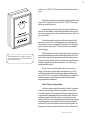
How to Operate the Stoker Control
There are four operator interfaces on the stoker control.
The operator interfaces are one rocker switch and three, 16-
position rotary switches.
The rocker switch is a power switch that controls only the
coal feeder motor. For normal operation, this switch should be
placed in the "on" position. This switch's operation can be verified
by a small red light above the coal feeder receptacle being on when
the switch is on.
If the stove needs to be shut down, simply place the rocker
switch in the "off" position. The small light above the coal feeder
receptacle will turn off.
The other three switches are the customer's adjustments for
the timers (on time, off time, distribution blower time). These
switches can adjust each timer individually from 1 minute to 15
minutes in 1 minute increments. Do not set timers to 0.
The "on" time and the "off" time should be programmed to a
minimum time that keeps the coal burning during the maintenance
cycling mode. The distribution blower time should be programmed
for a time which is long enough to move the excess heat from the
stove to the room heated. If this time is programmed for a longer
time than the "off" time the distribution blower will operate con-
stantly. This will have no damaging effect on the stoker control.
Recommended timer settings to start are, "on" 4 minutes,

14
DO NOT BURN WET COAL
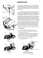
feed indicator
Over Fired, No Good
WASTING COAL
POSSIBLE DAMAGE TO UNIT
Max feed rate
Low feed rate
Feed Adjustment
Adjust feed rate by turning adjuster clockwise to
increase and counterclockwise to decrease. Each complete
turn will move the fire about 1".
The feed indicator on the side of the feeder shows how
far the pusher moves each stroke. There are dots above the
indicator spaced 1/8 " apart. A movment of one dot would
give a low burn, two dots medium and three dots high.
Lock adjuster with wing nut after adjusting.
See drawings at left.
"off" 12 minutes, extend timer 2 minutes. You may find that these
settings produce too much heat in pilot mode. If so, you can reduce
the "on" time and increase the "off" time. However, be aware that
you can go too far and have the fire go out. It is best to adjust one
minute at a time.
To start a fire you first pour rice coal into the hopper. With the
thermostat turned up and the stoker running, the coal will begin to
feed onto the grate inside the stove. This process can be speeded up
by adjusting the feed rate to the maximum position. When the coal
starts to come up out of the grate and is almost up to the area where
the holes start, turn the feed rate back to about 3/8" and turn off the
feed motor with the switch on the side of the stoker. Place some
crumbled newspaper and fine kindling (6" to 8" long) on the grate and
ignite. When kindling is burning good, add some rice coal on top of
it. After the coal is burning, the feed motor can be turned on and the
coal fire will continue to get larger. Fresh coal will continue to be
pushed onto the grate and ashes will be pushed off the grate. The
feed rate must be adjusted so the coal is burned up and turned to
ashes before the coal gets one inch from the end of the grate. Too
high a feed rate will push unburned coal off the coal grate, therefore
OPERATION

15
DO NOT BURN WET COAL
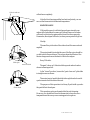
Slide closed
Cycle in and out
will not burn completely.
After the fire is burning and the feed rate is adjusted, you can
now set the thermostat to the desired temperature.
MAINTENANCE
With each hopper of coal that is burned approximately one
ashpan full of ashes must be removed. Failure to remove the ashes
will result in a blocked up grate and the fire will not burn properly.
Remember, the ashpan will be hot, so always wear protective gloves.
Weekly:
The small tray in the side of the stoker should be removed and
emptied.
The spring handle located at the rear of the flue-pipe should be
cycled in and out several times. This action cleans the interior of the
heat exchanger and causes the dust to fall into the ashpan.
Every 3 Months:
The grate "clean-out" slide should be opened and reclosed as
shown in drawings at left.
In the "closed" position, be sure the "grate clean-out" plate slide
is straight across as shown.
The easiest way to handle this slide is through the ash door with
a poker inserted into the hole at the end.
The purpose of this operation is to let any fly ash build-up under
the grate fall into the ashpan.
This operation can be performed while the unit is burning.
However, you should first lower the thermostat to lower the stove
temperature and be sure you are wearing protective gloves.
Slide open
clean-out slide

16
DO NOT BURN WET COAL
This operation can also be performed when the unit is not burning
by lifting out the grate inserts and removing fly ash with the vacuum
cleaner.
Annually:
At the end of the heating season is the best time to perform annual
maintenance. The reason is rust and corrosion can form much faster in
the high humidity of summer.
Remove all coal from hopper.
Remove all ashes.
Remove and clean flue pipe.
Check chimney and clean if necessary.
Remove hopper and check for rust at bottom edges. If rust is
found, remove it with a file or sandpaper and paint the area with spray
paint available from your dealer.
Check the feeder for rust and corrosion where the hopper fits into
it.
Check the pusher block to see if it moves freely. This can best be
done by shaking the adjuster rod. If it does not move freely, it should be
removed and cleaned. Also remove any rust or corrosion from the area
where the pusher block slides and spray with WD-40 or other rust
preventing spray. To remove pusher block - - Remove cover, remove
wing nut, adjuster, and adjuster tube. Remove motor mount with motor
in place and cord still attached. Swing pusher assembly up as high as it
will go. Remove feed indicator from side with Allen wrench. Now the
pusher block can be removed. To reinstall -- just reverse the
procedure. If the pusher block cannot be moved, call your
dealer.
Always empty hopper when not burning for more than a
week. When left standing for long periods with wet coal, the
pusher block will rust and corrode, causing it to seize. If the
stoker is then turned "on", damage to the pusher assembly and
feed motor will result. This will be considered neglect and will
IMPORTANT
è
IMPORTANT
è

17
DO NOT BURN WET COAL
void the warranty on those parts. Always check to see if moving parts
are free before using if the unit has not been burned for a period of time.
This can best be determined by shaking the adjuster rod.
TROUBLE-SHOOTING
FEEDING PROBLEMS
Wet Coal -- Wet coal does not flow the same as dry coal. There-
fore, the feed rate will change with wet coal. If it is too wet, it may not
feed at all. Wet coal can also cause a sulfur odor.
Wrong Size Coal -- The Verti-Flow System is designed to burn
rice (or buckwheat coal if rice is not available) If buckwheat coal is
burned, raise the draft setting from .04 to .06. Larger coal will not feed
or burn properly.
Hopper Blocked -- Sometimes wood, paper, or other foreign
objects accidently end up in your coal bin and can slow down or block
the flow of coal. You may have to empty the hopper to find the block-
age.
Pusher Out Of Adjustment -- This can happen when more than
one person tends the stoker. One person does not tell others what
adjustments were made.
Gas Alarm Buzzes or Sulfur Odor Exists -- A sulfur smell may be
noticed when the top door is opened during operation with wet or
damp coal. This is normal. However, it is not recommended that wet
coal be used or the top door be opened for more than a few seconds
while burning to inspect the fire.
Lack of draft or a down draft in the chimney will cause gases to
escape from the unit. No stove will function properly without draft. Any
draft problem should be corrected before use.
A draft inducer may be installed to increase draft in marginal
situations.

18
DO NOT BURN WET COAL
The installation should be performed by your dealer who is factory
trained to correct any problem on initial start-up. After proper installation,
many years of trouble-free operation can be expected.
Stoker Control Trouble-Shooting
This trouble-shooting guide is designed to help the customer find basic
problems external to the stoker timer. If a problem cannot be located by
using this guide, servicing of the stoker control or replacement may be
required. This should be done by qualified personnel.
PROBLEM: No motors or lights will turn on.
Check the AC power cord to the stoker control.
Check the 3 amp fuse on the side panel of the stoker timer. (Replace
only with a 3 amp slow blow fuse.)
PROBLEM: Lights on the stoker control are on, but motors will not
operate.
Check the AC power plugs from the motors (are they securely
plugged into the correct outlet.)
PROBLEM: One of the motors will not operate.
Check if the light above the receptacle is lit. Check the AC power
plug from the motor (is it securely plugged into the correct outlet.)
PROBLEM: The motors are cycling on and off, but not in the correct
order.
Check the AC power plugs from the motors (are they securely
plugged into the correct outlet.)
PROBLEM: Coal feeder motor will not turn on.
Check if the red light is lit, if not, check if the feed motor switch is
turned on.
PROBLEM: The motors turn on and off as programmed, but the
room temperature is below the thermostat setting.

19
DO NOT BURN WET COAL
Check the connections from the stoker control to the thermostat.
Check the thermostat for proper operation.
PROBLEM: The motors do not turn off even when the room tempera-
ture is above the thermostat set point.
Check that the programmed off time is not for 0 minutes.

20
DO NOT BURN WET COAL
1
2
3
4
5
6
7
7
8
9
10
11
12
13
16
17
18
19
20
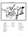
Feeder Parts
14
1. (2)grate inserts
2. grate holder
3. grate angle
4. feeder body
5. clean-out slide
6. pusher arm
7. (2) pillow block bearings
8. feed motor
9. capacitor
10. motor mount
11. pusher block
12. adjuster rod
13. adjuster tube
14. adjuster
15. wing nut
16. motor cover
17. cam arm cover
18. cam arm
19. dust tray
20. feed indicator
21. cam bearing
22. gasket
A (4) 1/4 x 5/8
B (3) 1/4 " nut
C (3) 3/8 x 1 1/4
D (3) 3/8 flat washer
E (2) 3/8 nuts
F (1) 1/4 x 1 1/4 Allen
G (4) 10-32 x 5/8 Allen
H (1) 8-32 screw and nut
I (1) 1/4 x 1/2 grade 8
J (3) 5/16 x 3/4
K (3) 5/16 nuts
L (1) 1/4 x 5/8 button head
A
A
A
A
B
B
B
C
C
C
D
D
D
21
E
F
G
G
G
G
H
I
J
J
J
K
K
K
L
15
22
La pagina si sta caricando...
La pagina si sta caricando...
La pagina si sta caricando...
-
 1
1
-
 2
2
-
 3
3
-
 4
4
-
 5
5
-
 6
6
-
 7
7
-
 8
8
-
 9
9
-
 10
10
-
 11
11
-
 12
12
-
 13
13
-
 14
14
-
 15
15
-
 16
16
-
 17
17
-
 18
18
-
 19
19
-
 20
20
-
 21
21
-
 22
22
-
 23
23


Harman Stove Company Magnum Stoker Manuale utente
- Categoria
- Stufe
- Tipo
- Manuale utente
- Questo manuale è adatto anche per
in altre lingue
Altri documenti
-
United States Stove Company AP5617-W Manuale del proprietario
-
-
-
 Redexim Verti-Cut® 1300 Manuale del proprietario
-
 Redexim Verti-Drain® 1517 Manuale del proprietario
-
Dovre Dovre Fireplace 2020 Scheda dati
-
 DEVILLE C07834 Manuale del proprietario
-
 DEVILLE C07832 Manuale del proprietario
-
 DEVILLE C07856 Manuale del proprietario
-
Dovre TAI55M Manuale del proprietario


