ATEN VM3404H Guida Rapida
- Categoria
- Scatole di interruttori seriali
- Tipo
- Guida Rapida
Questo manuale è adatto anche per

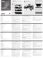
Hardware Review
A
Front View
1. LCD Display
2. Input Pushbuttons
3. Output Pushbuttons
4. Prev / Next Pushbuttons
5. Function Pushbuttons
Rear View
1. Power Socket
2. Power Switch
3. Grounding Terminal
4. HDMI Input Ports
5. HDBaseT Output Ports
6. HDMI Output Ports
7. IR Channel Ports*
8. IR Port*
9. RS-232 Serial Port
10. Ethernet Port
* The IR Channel Ports are used for controlling the source and the display from
the local or remote locations; the IR Port is used for controlling the switch.
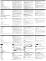
Hardware Installation
B
1. Use a grounding wire to ground the unit by connecting one end of the
wire to the grounding terminal, and the other end of the wire to a suitable
grounded object.
Note: Do not omit this step. Proper grounding helps to prevent damage to
the unit from surges or static electricity.
2. Connect up to 4 (VM3404H) or 9 (VM3909H) HDMI video sources to the
HDMI Input ports.
3. You can choose either of these two methods to transmit signals over a
distance.
1. Connect up to 4 (VM3404H) or 9 (VM3909H) HDBaseT display devices
directly to the HDBaseT Output ports using a RJ-45 cable.
2. Connect up to 4 (VM3404H) or 9 (VM3909H) HDMI display devices
via an HDBaseT receiver. (Connect the VM3404H / VM3909H to the
HDBaseT receiver using a RJ-45 cable. Then, connect the receiver to the
HDMI display device using a HDMI cable.)
4. (Optional) Connect up to 4 (VM3404H) or 9 (VM3909H) HDMI display
devices to the HDMI Output ports.
5. Connect IR receivers / transmitters into the IR Channel ports for controlling
the source and the display from the local or remote locations.
6. (Optional) If using the Browser Operation features, plug a Cat 5e cable from
the LAN into the VM3404H / VM3909H’s Ethernet port.
7. (Optional) If you are using the serial control function, use an appropriate
RS-232 serial cable to connect the computer or serial controller to the
VM3404H / VM3909H’s female RS-232 Serial port.
8. Plug the power cord supplied with the package into the VM3404H /
VM3909H’s 3-prong AC socket, and then into an AC power source.
9. (Optional) Connect an IR Receiver into the IR port for controlling the switch.
10. Power on the VM3404H / VM3909H and all devices in the installation.
Operation
The VM3404H / VM3909H can be confi gured and operated locally on the
front panel LCD via pushbuttons; remotely over a standard TCP/IP connection
via graphical user interface(GUI) using a web browser; or by a RS-232 serial
controller.
Front Panel Operation
Basic Navigation
The VM3404H / VM3909H’s front panel display operation is intuitive and
convenient. Please note the following operation conventions:
•
Use the Menu pushbutton to access the Menu page options.
•
Use the Profi le pushbutton to cycle through the profi les (input and output
connection)
•
Use the Cancel pushbutton to go back a level, return to the Initial screen, or
exit.
•
Use the Enter pushbutton to select options and confi rm operations.
•
The VM3404H / VM3909H provides Prev / Next pushbuttons to navigate
the menus.
To operate the device using the front panel display, the default password is
1234.
Remote Operation
The VM3404H / VM3909H supports three levels of remote users with various
operational privileges, and up to 8/18 users can log into the GUI at one time.
Logging In
To access the Browser GUI, type the VM3404H / VM3909H’s IP address into
the address bar of any browser. If a Security Alert dialog box appears, accept
the certifi cate – it can be trusted. The welcome screen appears.
•
The VM3404H / VM3909H’s default IP address is http://192.168.0.60.
•
The default username and password are: administrator/password.
Note: The VM3404H / VM3909H username supports lower case letters only.
B
Package Contents
1 VM3404H / VM3909H HDMI HDBaseT-Lite Matrix Switch
1 Power Cord
1 Mounting Kit
1 User Instructions
VM3404H
Front View
VM3909H
Front View
VM3404H
Rear View
VM3909H
Rear View
Hardware Installation
VM3404H / VM3909H 4x4 / 9x9 HDMI HDBaseT-Lite Matrix Switch Quick Start Guide
www.aten.com
VM3404H / VM3909H Commutateur matriciel HDBaseT-Lite HDMI 4x4 / 9x9 Guide de démarrage rapide
www.aten.com
VM3404H / VM3909H 4x4 / 9x9 HDMI HDBaseT-Lite Matrix Switch Kurzanleitung
www.aten.com
VM3404H / VM3909H Conmutador de matriz HDMI HDBaseT-Lite 4x4 / 9x9 Guía de inicio rápido
www.aten.com
VM3404H / VM3909H Switch matrix HDMI HDBaseT-Lite 4x4 / 9x9 Guida rapida
www.aten.com
1 2
3
3
54
1
2
4 5
1
1
2
2
3
3
4
4
5
5
6
6
7
7
MENU
PROFI LE
9
9
8
8
CANCE L ENTER
5
4
6
7
4
9
2
6
7
5
10
10
8
8
3
1
2
1
3
9
5
4
3
6
7
8
9
1
2
or
© Copyright 2015 ATEN
®
International Co., Ltd.
ATEN and the ATEN logo are trademarks of ATEN International Co., Ltd. All rights reserved. All
other trademarks are the property of their respective owners.
This product is RoHS compliant.
Part No. PAPE-1223-E20G Printing Date: 08/2015
4x4
/
9x9 HDMI HDBaseT-Lite Matrix Switch
Quick Start Guide
VM3404H / VM3909H
ATEN VanCryst
™
Important Notice
Considering environmental protection, ATEN does not provide a fully
printed user manual for this product. If the information contained in the
Quick Start Guide is not enough for you to confi gure and operate your
product, please visit our website www.aten.com, and download
the full user manual.
Online Registration
http://eservice.aten.com
Technical Phone Support
International:
886-2-86926959
All information, documentation, firmware, software utilities, and
specifi cations contained in this package are subject to change without
prior notification by the manufacturer. Please visit our website http://
www.aten.com/download/?cid=dds for the most up-to-date versions.
이 기기는 업무용 (A 급 ) 전자파 적합기기로서 판매자 또는 사용자는 이점
을 주의하시기 바라며 , 가정외의 지역에서 사용하는 것을 목적으로합니다 .
The following contains information that relates to China:
North America:
1-888-999-ATEN Ext: 4988
United Kingdom:
44-8-4481-58923
EMC Information
FEDERAL COMMUNICATIONS COMMISSION INTERFERENCE STATEMENT:
This equipment has been tested and found to comply with the limits for a Class A
digital device, pursuant to Part 15 of the FCC Rules. These limits are designed to provide
reasonable protection against harmful interference when the equipment is operated
in a commercial environment. This equipment generates, uses, and can radiate radio
frequency energy and, if not installed and used in accordance with the instruction
manual, may cause harmful interference to radio communications. Operation of this
equipment in a residential area is likely to cause harmful interference in which case the
user will be required to correct the interference at his own expense.
FCC Caution: Any changes or modifi cations not expressly approved by the party
responsible for compliance could void the user's authority to operate this equipment.
CE Warning: This is a class A product. In a domestic environment this product may cause
radio interference in which case the user may be required to take adequate measures.
This device complies with Part 15 of the FCC Rules. Operation is subject to the following
two conditions:(1) this device mat not cause harmful interference, and(2) this device
must accept any interference received, including interference that may cause undesired
operation.
Présentation matérielle
A
Vue avant
1. Affi chage LCD
2. Boutons-poussoirs d'entrée
3. Boutons-poussoirs de sortie
4. Boutons-poussoirs Préc. / Suiv
5. Boutons-poussoirs de fonction
Vue arrière
1. Prise d'alimentation
2. Commutateur d'alimentation
3. Borne de mise à la terre
4. Ports d'entrée HDMI
5. Ports de sortie HDBaseT
6. Ports de sortie HDMI
7. Ports de canal IR*
8. Port IR*
9. Port série RS-232
10.Port Ethernet
* Les ports de canal IR sont utilisés pour contrôler la source et l'affi chage
depuis les emplacements locaux ou distants. Le port IR est utilisé pour
contrôler le commutateur.
Installation matérielle
B
1. Utilisez un fi l de terre pour relier l'unité à la terre en connectant une
extrémité du fi l à la borne de mise à la terre, et l'autre extrémité du fi l à un
objet mis à la terre approprié.
Remarque: Ne négligez pas cette étape. Une mise à la terre appropriée
aide à prévenir les dommages à l'appareil due aux surtensions
ou l'électricité statique.
2. Connectez jusqu'à 4 (VM3404H) ou 9 (VM3909H) sources vidéo HDMI aux
ports d'entrée HDMI.
3. Vous pouvez choisir l'une de ces deux méthodes pour transmettre des
signaux sur une distance.
1. Connectez jusqu'à 4 (VM3404H) ou 9 (VM3909H) périphériques
d'affi chage HDBaseT directement aux ports de sortie HDBaseT en
utilisant un câble RJ-45.
2. Connectez jusqu'à 4 (VM3404H) ou 9 (VM3909H) périphériques
d'affi chage HDMI via un récepteur HDBaseT. (Connectez le VM3404H
/ VM3909H au récepteur HDBaseT en utilisant un câble RJ-45. Puis,
connectez le récepteur au périphérique d'affi chage HDMI en utilisant un
câble HDMI.)
4. (En option) Connectez jusqu'à 4 (VM3404H) ou 9 (VM3909H) périphériques
d'affi chage HDMI aux ports de sortie HDMI.
5. Connectez des émetteurs / récepteurs IR dans les ports de canal IR pour
contrôler la source et l'affi chage depuis les emplacements locaux ou
distants.
6. (En option) Si vous utilisez les fonctions d'opération via navigateur, branchez
un câble Cat 5e depuis le réseau local au port Ethernet du VM3404H /
VM3909H.
7. (En option) Si vous utilisez la fonction de commande série, utilisez un câble
série RS-232 approprié pour connecter l'ordinateur ou le contrôleur série au
port série RS-232 femelle du VM3404H / VM3909H.
8. Branchez le cordon d'alimentation fourni dans l'emballage dans la prise CA
à 3 broches du VM3404H / VM3909H, puis dans une source d'alimentation
secteur.
9. Connectez un récepteur IR dans le port IR pour contrôler le commutateur.
10. Allumez le VM3404H / VM3909H et tous les périphériques dans
l'installation.
Opération
Le VM3404H / VM3909H peut être confi guré et géré localement sur l'écran
LCD du panneau avant via des boutons-poussoirs ; à distance sur une
connexion TCP/IP standard via l'interface utilisateur graphique (GUI) à l'aide
d'un navigateur Web ; ou par un contrôleur série RS-232.
Opération via le panneau avant
Navigation de base
L'opération via l'affi chage du panneau avant du VM3404H / VM3909H est
intuitive et pratique. Veuillez noter les conventions d'opération suivantes :
•
Utilisez le bouton-poussoir Menu pour accéder aux options de la page menu.
•
Utilisez le bouton-poussoir Profi l pour faire défi ler les profi ls (connexion
entrée et sortie)
•
Utilisez le bouton-poussoir Annuler pour remonter d'un niveau, retourner à
l'écran initial ou quitter.
•
Utilisez le bouton-poussoir Entrée pour sélectionner les options et confi rmer
les opérations.
•
Lee VM3404H / VM3909H fournit des boutons-poussoirs Préc / Suiv pour
naviguer dans les menus.
Pour gérer l'appareil en utilisant l'affi chage du panneau avant, le mot de passe
par défaut est 1234.
Opération à distance
Le VM3404H / VM3909H prend en charge trois niveaux d'utilisateurs distants
avec divers privilèges opérationnels, et jusqu'à 8/18 utilisateurs peuvent se
connecter à l'interface utilisateur graphique en même temps.
Connexion
Pour accéder à l'interface utilisateur graphique du navigateur, saisissez
l'adresse IP du VM3404H / VM3909H dans la barre d'adresse d'un navigateur.
Si une boîte de dialogue alerte de sécurité apparaît, acceptez le certifi cat, vous
pouvez lui faire confi ance. L'écran de bienvenue apparaît.
•
L'adresse IP par défaut du VM3404H / VM3909H est http://192.168.0.60.
•
Le nom d'utilisateur et le mot de passe par défaut sont : administrator/
password.
Remarque: Le nom d'utilisateur du VM3404H / VM3909H ne prend en charge
que les lettres minuscules.
Hardware Übersicht
A
Vorderseite
1. LCD Anzeige
2. Eingabe Drucktasten
3. Ausgabe Drucktasten
4. Zurück / Weiter Drucktasten
5. Funktion Drucktasten
Rückseite
1. Netzbuchse
2. Netzschalter
3. Erdungsanschluss
4. HDMI Eingänge
5. HDBaseT Ausgänge
6. HDMI Ausgänge
7. IR Kanal Anschlüsse*
8. IR Anschluss*
9. RS-232 serieller Anschluss
10.Ethernet Anschluss
* Die IR Kanal Anschlüsse werden für die Steuerung der Quelle und der
Anzeige von lokalen oder Remote Standorten verwendet. Der IR Anschluss
wird für die Steuerung des Switch verwendet.
Hardware-Installation
B
1. Verwenden Sie ein Erdungskabel, um das Gerät zu erden, indem Sie ein
Ende des Kabels mit dem Erdungsanschluss verbinden, und das andere Ende
des Kabels mit einem geeigneten geerdeten Gegenstand.
Hinweis: Lassen Sie diesen Schritt nicht aus. Eine ordnungsgemäße
Erdung hilft bei der Vermeidung von Schäden am Gerät durch
Stromspitzen oder statischer Elektrizität.
2. Schließen Sie bis zu 4 (VM3404H) oder 9 (VM3909H) HDMI Videoquellen
an den HDMI Eingängen an.
3. Sie können eine der beiden Methoden verwenden, um Signale zu
übertragen.
1. Schließen Sie bis zu 4 (VM3404H) oder 9 (VM3909H) HDBaseT Display
Geräte direkt an die HDBaseT Ausgänge mit einem RJ-45 Kabel an.
2. chließen Sie bis zu 4 (VM3404H) oder 9 (VM3909H) HDMI Display
Geräte über einen HDBaseT Empfänger an. (Schließen Sie den VM3404H
/ VM3909H an den HDBaseT Empfänger mit einem RJ-45 Kabel an.
Verbinden Sie den Empfänger anschließend mit einem HDMI Kabel mit
dem HDMI Display.)
4. (Optional) Schließen Sie bis zu 4 (VM3404H) oder 9 (VM3909H) HDMI
Display Geräte an die HDMI Ausgänge an.
5. Schließen Sie IR Empfänger / Sender an die IR Kanal Anschlüsse zur
Steuerung der Quelle und des Displays von lokalen oder Remote Standorten.
6. (Optional) Wenn Sie die Browserbedienfunktionen verwenden, schließen
Sie ein Cat 5e Kabel vom LAN an den VM3404H / VM3909H Ethernet
Anschluss an.
7. (Optional) Wenn Sie die serielle Steuerungsfunktion nutzen, verwenden
Sie ein geeignetes, serielles RS-232 Kabel, um den Computer oder seriellen
Controller an den RS-232 serieller Anschluss des VM3404H / VM3909H
anzuschließen.
8. Stecken Sie das im Lieferumfang enthaltene Stromkabel in die 3-polige
Netzbuchse des VM3404H / VM3909H und anschließend in eine Steckdose.
9. Verbinden Sie einen IR Empfänger mit dem IR Anschluss, um den Switch zu
steuern.
10.Schalten Sie den VM3404H / VM3909H und alle anderen Geräte de
Installation ein.
Bedienung
Der VM3404H / VM3909H kann lokal am LCD an der Vorderseite über
Drucktasten, Remote über eine Standard TCP/IP Verbindung über eine grafi sche
Benutzeroberfl äche (GUI) mit einem Browser, oder über einen seriellen RS-232
Controller konfi guriert und bedient werden.
Vorderseite Bedienung
Grundlegende Navigation
Die Bedienung über das VM3404H / VM3909H Display an der Vorderseite ist
intuitiv und komfortabel. Bitte beachten Sie die folgenden Bedienungshinweise:
•
Verwenden Sie die Menü Drucktaste für den Zugriff auf die Menüseite
Optionen.
•
Verwenden Sie die Profi l Drucktaste für den Wechsel der Profi le (Eingangs-
und Ausgangsverbindung)
•
Verwenden Sie die Abbrechen Drucktaste, um eine Ebene zurückzugehen,
die Startseite wieder aufzurufen, oder zum Beenden.
•
Verwenden Sie die Enter Drucktaste zur Auswahl von Optionen und
Bestätigung von Eingaben.
•
Der VM3404H / VM3909H bietet Zurück / Weiter Drucktasten zum
Navigieren durch die Menüs.
Das Standardkennwort zur Bedienung des Gerätes über das Display an der
Vorderseite ist 1234.
Fernbedienung
Der VM3404H / VM3909H unterstützt drei Ebenen von Remote Nutzern
mit verschiedenen Berechtigungen, und bis zu 8/18 Benutzer können sich
gleichzeitig am GUI anmelden.
Anmelden
Um auf das Browser GUI zuzugreifen, geben Sie die IP-Adresse des VM3404H /
VM3909H in die Adresszeile eines Browsers ein. Akzeptieren Sie das Zertifi kat,
wenn ein Sicherheitswarnfenster angezeigt wird – es ist vertrauenswürdig. Die
Willkommensseite wird angezeigt.
•
Die Standard IP-Adresse des VM3404H / VM3909H ist http://192.168.0.60.
•
Der Standard Benutzername und das Kennwort sind: administrator/password.
Hinweis: Der VM3404H / VM3909H Benutzername unterstützt nur
Kleinbuchstaben.
Revisión del hardware
A
Vista frontal
1. Pantalla LCD
2. Pulsadores de entrada
3. Pulsadores de salida
4. Pulsadores Anterior / Siguiente
5. Pulsadores de función
Vista posterior
1. Toma de corriente
2. Interruptor de encendido
3. Terminal de conexión a tierra
4. Puertos de entrada HDMI
5. Puertos de salida HDBaseT
6. Puertos de salida HDMI
7. Puertos del canal de infrarrojos*
8. Puerto de infrarrojos*
9. Puerto serie RS-232
10.Puerto Ethernet
* Los puertos del canal de infrarrojos se usan para controlar la fuente y la
visualización desde las ubicaciones locales o remotas; el puerto de infrarrojos
se utilizan para controlar el conmutador.
Instalación del hardware
B
1. Utilice un cable de conexión a tierra para conectar la unidad a tierra
mediante la conexión de un extremo del cable al terminal de conexión a
tierra, y el otro extremo del cable a un objeto conectado a tierra adecuado.
Nota:
No omita este paso. Una conexión a tierra adecuada ayuda a
evitar daños en la unidad provocados por los picos de tensión o
por la electricidad estática.
2. Permite conectar hasta cuatro (VM3404H) o nueve (VM3909H) fuentes de
vídeo HDMI a los puertos de entrada HDMI.
3. Puede elegir cualquiera de estos dos métodos para transmitir las señales a
través de una gran distancia.
1. Conecte hasta cuatro (VM3404H) o nueve (VM3909H) dispositivos de
visualización HDBaseT directamente a los puertos de salida HDBaseT
utilizando un cable RJ-45.
2. Conecte hasta cuatro (VM3404H) o nueve (VM3909H) dispositivos
de visualización HDMI a través de un receptor HDBaseT. (Conecte el
VM3404H / VM3909H al receptor HDBaseT con un cable RJ-45. A
continuación, conecte el receptor al dispositivo de visualización HDMI
con un cable HDMI.)
4. (Opcional) Conecte hasta cuatro (VM3404H) o nueve (VM3909H)
dispositivos de visualización HDMI a los puertos de salida HDMI.
5. Conecte los receptores o transmisores de infrarrojos a los puertos del
canal de infrarrojos para controlar la fuente y la visualización desde las
ubicaciones locales o remotas.
6. (Opcional) Si utiliza las funciones de operaciones con navegador, conecte un
cable Cat 5e de la LAN al puerto Ethernet del VM3404H / VM3909H.
7. (Opcional) Si está utilizando la función de control en serie, utilice un cable
RS-232 serie adecuado para conectar el ordenador o el controlador en serie
al puerto serie RS-232 hembra del VM3404H / VM3909H.
8. Conecte el cable de alimentación incluido en la caja a la toma de CA de
tres clavijas del VM3404H / VM3909H y, a continuación, a la fuente de
alimentación de CA.
9. Conecte un receptor de infrarrojos al puerto de infrarrojos para controlar
el conmutador.
10.Encienda el VM3404H / VM3909H y todos los dispositivos de la instalación.
Funcionamiento
El VM3404H / VM3909H puede confi gurarse y controlarse de forma local
mediante los pulsadores del LCD del panel delantero, de forma remota a través
de una conexión TCP/IP estándar mediante la interfaz gráfi ca de usuario (GUI)
desde un navegador web, o con un controlador serie RS-232.
Funcionamiento del panel delantero
Navegación básica
El funcionamiento del panel delantero de visualización del VM3404H
/ VM3909H resulta intuitivo y cómodo. Tenga en cuenta las siguientes
convenciones de funcionamiento:
•
Utilice el pulsador Menú para acceder a las opciones de la página de menús.
•
Utilice el pulsador Perfi l para recorrer los distintos perfi les (conexión de
entrada y salida)
•
Utilice el pulsador Cancelar para retroceder un nivel, volver a la pantalla
inicial o salir.
•
Utilice el pulsador Entrar para seleccionar las opciones y confi rmar las
operaciones.
•
El VM3404H / VM3909H contiene los pulsadores Anterior / Siguiente para
desplazarse por los menús.
La contraseña predeterminada para utilizar el dispositivo con la pantalla del
panel delantero es 1234.
Funcionamiento remoto
El VM3404H / VM3909H admite tres niveles de usuarios remotos con distintos
privilegios operativos, y hasta 8/18 usuarios pueden iniciar sesión en la interfaz
gráfi ca de usuario al mismo tiempo.
Inicio de sesión
Para acceder a la interfaz gráfi ca de usuario de navegador, escriba la dirección
IP del VM3404H / VM3909H en la barra de direcciones de cualquier navegador.
Si aparece un cuadro de diálogo de aviso de seguridad, acepte el certifi cado,
ya que puede confi ar en él. Aparece la pantalla de bienvenida.
•
La dirección IP predeterminada del VM3404H / VM3909H es
http://192.168.0.60.
•
El nombre de usuario y la contraseña predeterminados son: administrator/
password
.
Nota: El nombre de usuario del VM3404H / VM3909H solo admite letras en
minúscula.
Panoramica hardware
A
Vista frontal
1. Schermo LCD
2. Pulsanti push ingresso
3. Pulsanti push uscita
4. Pulsanti push precedente / successivo
5. Pulsanti push funzione
Vista posterior
1. Presa di alimentazione
2. Interruttore di accensione
3. Terminale di messa a terra
4. Porte ingresso HDMI
5. Porte uscita HDBaseT
6. Porte uscita HDMI
7. Porte canale IR*
8. Porta IR*
9. Porta seriale RS-232
10.Porta Ethernet
* Le porte canale IR sono utilizzate per il controllo della sorgente e dello
schermo da posizioni vicine o remote; la porta IR è utilizzata per il controllo
dello switch.
Installazione hardware
B
1. Usare un cavo di messa a terra per la messa a terra dell'unità collegandone
una estremità al terminale di messa a terra e l'altra estremità ad un oggetto
dotato di messa a terra idoneo.
Nota:
Non ignorare questo passaggio. Una messa a terra adeguata
aiuta ad evitare danni all'unità dovuti a sovratensioni o elettricità
statica.
2. Collegare fi no a 4 (VM3404H) o 9 (VM3909H) sorgenti video HDMI alle
porte ingresso HDMI.
3. È possibile scegliere uno di questi metodi per trasmettere i segnali a
distanza.
1. Collegare fi no a 4 (VM3404H) o 9 (VM3909H) dispositivi di
visualizzazione HDBaseT direttamente alle porte uscita HDBaseT
mediante un cavo RJ-45.
2. Collegare fi no a 4 (VM3404H) o 9 (VM3909H) dispositivi di
visualizzazione HDMI mediante un ricevitore HDBaseT. (Collegare il
VM3404H / VM3909H al ricevitore HDBaseT mediante un cavo RJ-
45. Quindi, collegare il ricevitore al dispositivo di visualizzazione HDMI
mediante un cavo HDMI.)
4. (Opzionale) Collegare fi no a 4 (VM3404H) o 9 (VM3909H) dispositivi di
visualizzazione HDMI alle porte uscita HDMI.
5. Collegare i ricevitori / trasmettitori IR alle porte canale IR per il controllo
della sorgente e dello schermo da posizioni vicine o remote.
6. (Opzionale) Quando vengono utilizzate le funzioni operazioni browser,
collegare un cavo Cat 5e dalla LAN alla porta Ethernet del VM3404H /
VM3909H.
7. (Opzionale) Quando viene utilizzata la funzione porta seriale, usare un cavo
seriale RS-232 appropriato per il collegamento del computer o controller
seriale alla porta seriale RS-232 femmina del VM3404H / VM3909H.
8. Collegare il cavo di alimentazione contenuto nella confezione alla presa CA
a 3 poli del VM3404H / VM3909H, quindi a una sorgente di alimentazione
CA.
9. Collegare un ricevitore IR alla porta IR per il controllo dello switch.
10.Accendere il VM3404H / VM3909H e tutti i dispositivi coinvolti
nell'installazione.
Funzionamento
Il VM3404H / VM3909H può essere confi gurato e utilizzato localmente tramite
il pannello LCD frontale utilizzando i pulsanti push; da remoto tramite una
connessione TCP/IP standard utilizzando l'interfaccia grafi ca e il browser web;
o tramite un controller seriale RS-232.
Funzionamento del pannello frontale
Navigazione di base
Il funzionamento dello schermo del pannello frontale del VM3404H /
VM3909H è comodo e intuitivo. Attenersi alle seguenti convenzioni sul
funzionamento:
•
Usare il pulsante push Menu per accedere alle opzioni della pagina menu.
•
Usare il pulsante push Profi lo per scorrere i profi li (collegamento di ingresso
e uscita)
•
Usare il pulsante push Annulla per tornare indietro di un livello, tornare alla
schermata iniziale o uscire.
•
Usare il pulsante push Invio per selezionare le opzioni e confermare le
operazioni.
•
Il VM3404H / VM3909H dispone di pulsanti push Precedente / Successivo
per scorrere i menu.
Per utilizzare il dispositivo mediante lo schermo del pannello frontale, la
password predefi nita è 1234.
Funzionamento da remoto
Il VM3404H / VM3909H supporta tre livelli di utenti remoti con diversi privilegi
di utilizzo, e fi no a 8/18 utenti possono accedere contemporaneamente
all'interfaccia grafi ca.
Accesso
Per accedere all'interfaccia grafi ca del browser, digitare l'indirizzo IP del
VM3404H / VM3909H nella barra degli indirizzi del browser. Se viene
visualizzata la fi nestra di dialo
go avviso sicurezza, accettare il certifi cato (può
essere attendibile). Viene visual
izzata la schermata di benvenuto.
•
L'indirizzo IP predefi nito del VM3404H / VM3909H è http://192.168.0.60.
•
Il nome utente e la password predefi niti sono: administrator/password.
Nota: il nome utente del VM3404H / VM3909H supporta solo lettere
minuscole.
A
Hardware Review
La pagina si sta caricando...
-
 1
1
-
 2
2


ATEN VM3404H Guida Rapida
- Categoria
- Scatole di interruttori seriali
- Tipo
- Guida Rapida
- Questo manuale è adatto anche per
in altre lingue
- English: ATEN VM3404H Quick start guide
- français: ATEN VM3404H Guide de démarrage rapide
- español: ATEN VM3404H Guía de inicio rápido
- Deutsch: ATEN VM3404H Schnellstartanleitung
- русский: ATEN VM3404H Инструкция по началу работы
- português: ATEN VM3404H Guia rápido
- 日本語: ATEN VM3404H クイックスタートガイド