
A
Overview
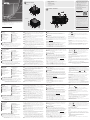
Front View
1
LCD Display
2
Function Pushbuttons
3
Input Pushbuttons (1-16)
4
Output Pushbuttons (1-16)
5
Alarm LED
6
Redundant Power LED
7
Primary Power LED
8
Handles
9
Recessed Handles
B
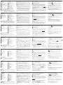
Hardware Installation
1
Use a grounding wire to ground the unit by connecting one end of
the wire to the grounding terminal, and the other end of the wire to a
suitable grounded object.
Note: Do not omit this step. Proper grounding helps to prevent
damage to the unit from surges or static electricity.
2
Unscrew the covers on the VM1600A’s rear panel and insert the I/O
boards into the horizontal slots (at least 1 Input x 1 Output; maximum
4 Inputs x 4 Outputs).
3
Connect your A/V source device(s) to the Input port(s) of the Input
Board on the VM1600A.
4
Connect your video display device(s) to the Video port(s) of the Output
Board on the VM1600A.
5
(Optional) Connect your audio input/output device(s) to the Audio
port(s) of the I/O Board on the VM1600A.
6
(Optional) If you are using the remote operation features (web GUI),
plug a Cat 5e cable from the network into the VM1600A’s Ethernet
port.
7
(Optional) If you are using a serial control function, use an appropriate
serial cable to connect the computer or serial controller to the
VM1600A’s female RS-232 serial port.
8
(Optional) If you are using the serial control function to control multiple
VM1600A, use an appropriate serial cable to connect the computer or
serial controller to the VM1600A’s female RS-485/RS-422 captive screw
connector. The VM1600A package includes a terminal block connector
that can be used for this connection.
9
Plug the power cord supplied with the package into the VM1600A’s
3-prong socket, and then into a power source.
10
(Optional) Plug in an additional power module for redundancy if
required.
Note: Secondary power modules are not included in the package.
11
Power on the VM1600A and all devices in the installation.
C
Operation
The VM1600A can be confi gured and operated locally via the front
panel display and pushbuttons, remotely over a standard TCP/IP
connection via graphical user interface (GUI) using a web browser, or by
an RS-232/RS-485/RS-422 serial controller. For more detailed information
about control operations, download the VM1600A user manual from our
website: www.aten.com
Front Panel Operation
The VM1600A’s front panel display operation is intuitive and convenient.
Please note the following operation conventions:
• Use the Input/Output pushbuttons to con gure port connections.
• Use the Video pushbutton to confi gure video connections.
• Use the Audio pushbutton to confi gure audio connections.
• Use the Profi le pushbutton to select a profi le or switch between the
connection profi les which have been added to the profi le selection list.
• Use the Menu pushbutton to access the Menu page options.
B
Front View
Rear View
Hardware Installation
© Copyright 2017 ATEN
®
International Co., Ltd.
ATEN and the ATEN logo are trademarks of ATEN International Co., Ltd. All rights reserved. All
other trademarks are the property of their respective owners.
Part No. PAPE-1223-C12G Printing Date: 10/2017
16 x 16 Modular Matrix Switch
Quick Start Guide
VM1600A
VM1600A 16 x 16 Modular Matrix Switch
www.aten.com
Commutateur matriciel modulaire 16 x 16 VM1600A
www.aten.com
Modularer 16 x 16-Matrix-Switch VM1600A
www.aten.com
VM1600A 16 x 16 Conmutador de matriz modular
www.aten.com
Switch matrix modulare VM1600A 16 x 16
www.aten.com
ATEN VanCryst
™
• Use the pushbutton to go back a level, return to the Initial screen,
or exit.
• Use the
pushbutton to go to the previous or next options.
Note: To operate the device using the front panel display, the default
password is 1234.
Remote Operation
The VM1600A supports three levels of remote users with various
operational privileges, and up to 16 users can log into the GUI at one
time.
Logging In
To access the Browser GUI, type the VM1600A’s IP address into the
address bar of any browser. If a Security Alert dialog box appears, accept
the certifi cate.
• VM1600A’s default IP address is 192.168.0.60.
• The default username and password are: administrator/password.
Note: The VM1600A username supports lower case letters only.
Rear View
1
Grounding Terminal
2
Power Switch
3
RS-232 Serial Port
4
Ethernet Port
5
RS-485 / RS-422 Serial Port
6
Primary Power Supply
7
Cable Strap
8
Redundant Power Slot (Optional)
9
Output Board Slots
10
Input Board slots
11
Fan Module
Package Contents
1 VM1600A Modular Matrix Switch
1 Power Cord
1 Terminal Block connector
1 Fan Module (pluggable)
1 Power Module (pluggable)
1 User Instructions
2
1
9
5
6
7
3
4
8
8
11
1
2
3
4
5
6
7
8
9
10
2
1
11
10
3
4
5
6
9
8
7
Support and Documentation Notice
All information, documentation, fi rmware,
software utilities, and specifi cations
contained in this package are subject to
change without prior notifi cation by
the manufacturer.
To reduce the environmental impact of our
products, ATEN documentation and software
can be found online at
http://www.aten.com/download/
Technical Support
www.aten.com/support
이 기기는 업무용(A급) 전자파적합기기로서 판매자 또는
사용자는 이 점을 주의하시기 바라며, 가정외의 지역에
서 사용하는 것을 목적으로 합니다.
Scan for
more information
EMC Information
FEDERAL COMMUNICATIONS COMMISSION INTERFERENCE
STATEMENT:
This equipment has been tested and found to comply with the limits
for a Class A digital device, pursuant to Part 15 of the FCC Rules.
These limits are designed to provide reasonable protection against
harmful interference when the equipment is operated in a commercial
environment. This equipment generates, uses, and can radiate radio
frequency energy and, if not installed and used in accordance with
the instruction manual, may cause harmful interference to radio
communications. Operation of this equipment in a residential area
is likely to cause harmful interference in which case the user will be
required to correct the interference at his own expense.
FCC Caution: Any changes or modifi cations not expressly approved by
the party responsible for compliance could void the user's authority to
operate this equipment.
Warning: Operation of this equipment in a residential environment
could cause radio interference.
This device complies with Part 15 of the FCC Rules. Operation is subject
to the following two conditions: (1) this device may not cause harmful
interference, and (2) this device must accept any interference received,
including interference that may cause undesired operation.
A
Hardware Review
A
Vue d'ensemble
Vue de devant
1
Écran LCD
2
Fonctions des boutons poussoirs
3
Boutons poussoirs d'entrée
(1-16)
4
Boutons poussoirs de sortie
(1-16)
5
LED d'alarme
6
LED d'alimentation redondante
7
LED d'alimentation primaire
8
Poignées
9
Poignées encastrées
B
Installation du matériel
1
Utilisez un fi l de mise à la terre en reliant une extrémité du fi l à la borne
de terre et l'autre extrémité à un objet mis à la terre adapté.
Remarque : N'ignorez pas cette étape. Une bonne mise à la terre
prévient des dommages sur l'appareil causés par les
surtensions et l'électricité statique.
2
Dévissez les caches sur le panneau arrière du VM1600A et insérez les
cartes E/S dans les fentes horizontales (au moins 1 entrée x 1 sortie,
4 entrées x 4 sorties au maximum).
3
Connectez votre/vos périphérique(s) source A/V au(x) port(s) d'entrée
de la carte d'entrée sur le VM1600A.
4
Connectez vos appareils d'affi chage vidéo aux ports vidéo de la carte
de sortie sur le VM1600A.
5
(Facultatif) Connectez votre/vos périphérique(s) d'entrée/sortie au(x)
port(s) d'entrée de la carte E/S sur le VM1600A.
6
(Facultatif) Si vous utilisez les fonctions de contrôle distant (Interface
utilisateur Web), branchez un câble Cat 5e au réseau et au port
Ethernet du VM1600A.
7
(Facultatif) Si vous utilisez une fonction de commande série, utilisez un
câble série approprié pour relier l'ordinateur ou contrôleur série au port
série RS-232 femelle du VM1600A.
8
(Facultatif) Si vous utilisez la fonction de commande série pour
contrôler plusieurs VM1600A, utilisez un câble série approprié pour
relier l'ordinateur ou contrôleur série au port RS-485/RS-422 femelle
du VM1600A. L'emballage du VM1600A comprend un connecteur de
bornier qui peut être utilisé pour cette connexion.
9
Branchez le cordon d'alimentation fourni dans l'emballage à la prise
secteur à 3 broches du VM1600A, puis sur une source d'alimentation.
10
(Facultatif) Branchez un module d'alimentation supplémentaire pour la
redondance si nécessaire.
Remarque : Les modules d'alimentation secondaires ne sont pas inclus
dans l'emballage.
11
Allumez le VM1600A et tous les appareils de l'installation.
C
Fonctionnement
Le VM1600A peut être confi guré et géré localement via l'affi chage et les
boutons du panneau avant, la télécommande IR ou à distance via une
connexion TCP/IP via une interface utilisateur graphique (GUI) avec un
navigateur Web, ou par un contrôleur série RS-232/RS-485/RS-422. Pour
des informations plus détaillées sur les opérations de contrôle, téléchargez
le manuel d'utilisation du VM1600A sur notre site : www.aten.com
Fonctionnement du panneau avant
Le fonctionnement du panneau avant du VM1600A est intuitif et
pratique. Veuillez noter les conventions de fonctionnement suivantes :
• Utilisez les boutons Input/Output pour con gurer les connexions aux
ports.
• Utilisez le bouton Video pour confi gurer les connexions vidéo.
• Utilisez le bouton Audio pour confi gurer les connexions audio.
• Utilisez le bouton Profi le pour sélectionner un profi l ou basculer entre les
profi ls de connexion qui ont été ajoutés à la liste de sélection des Profi ls.
• Utilisez le bouton Menu pour accéder aux options de la page Menu.
• Utilisez le bouton
pour revenir au niveau précédent, aller à l'écran
initial ou sortir.
• Utilisez les boutons
pour aller aux options suivantes ou
précédentes.
Remarque : Pour utiliser l'appareil avec l'affi chage du panneau avant, le
mot de passe par défaut est 1234.
Fonctionnement à distance
Le VM1600A prend en charge trois niveaux d'utilisateurs distants avec
divers privilèges opérationnels, et jusqu'à 16 utilisateurs peuvent se
connecter à l'interface graphique à la fois.
Connexion
Pour accéder à l'interface graphique du navigateur, saisissez l'adresse IP
du VM1600A dans la barre d'adresse d'un navigateur quelconque. Si une
boîte de dialogue d'alerte de sécurité s'affi che, acceptez le certifi cat, il est
de confi ance.
• L'adresse IP par défaut du VM1600A est 192.168.0.60.
• Le nom d'utilisateur et le mot de passe sont : administrator/password.
Remarque : Seules les lettres minuscules sont prises en charge pour les
noms d'utilisateur du VM1600A.
Vue de derrière
1
Borne de terre
2
Bouton d'alimentation
3
Port série RS-232
4
Port Ethernet
5
Port série RS-485 / RS-422
6
Alimentation primaire
7
Sangle pour câbles
8
Fente d'alimentation redondante
(Facultatif)
9
Fentes de carte de sortie
10
Fentes de carte d'entrée
11
Module ventilateur
A
Übersicht
Ansicht von vorne
1
LCD-Display
2
Funktionsdrucktasten
3
Eingangsdrucktasten (1-16)
4
Ausgangsdrucktasten (1-16)
5
Alarm-LED
6
Redundantes-Netzteil-LED
7
Primäres-Netzteil-LED
8
Griffe
9
Einlassgriffe
B
Hardwareinstallation
1
Verwenden Sie zum Erden des Gerätes ein Erdungskabel; verbinden Sie
ein Ende des Kabels mit der Erdungsklemme und das andere Ende mit
einem geeigneten geerdeten Objekt.
Hinweis: Lassen Sie diesen Schritt nicht aus. Eine angemessene
Erdung hilft bei der Verhinderung von Geräteschäden durch
Spannungsspitzen oder statische Elektrizität.
2
Lösen Sie die Abdeckungen an der Rückseite des VM1600A und
stecken Sie die I/O-Karten in die horizontalen Steckplätze (mindestens
1 Eingang x 1 Ausgang; maximal 4 Eingänge x 4 Ausgänge).
3
Schließen Sie Ihr(e) A/V-Quellgerät(e) an den/die Eingangsport(s) der
Eingangskarte(n) des VM1600A an.
4
Verbinden Sie Ihre Videoanzeigegeräte mit den Videoanschlüssen der
Ausgabekarte am VM1600A.
5
(Optional) Schließen Sie Ihr(e) Audio-Eingangs-/Ausgangsgerät(e) an
den/die Audio-Port(s) des I/O-Boards des VM1600A an.
6
(Optional) Wenn Sie Fernsteuerungsfunktionen
(Webbenutzeroberfl äche) nutzen möchten, schließen Sie ein Cat-5e-
Kabel des Netzwerks am Ethernet-Port des VM1600A an.
7
(Optional) Wenn Sie eine die Steuerungsfunktion nutzen möchten,
verwenden Sie ein geeignetes serielles Kabel zur Verbindung des
Computers oder seriellen Controllers mit der RS-232-Buchse des
VM1600A.
8
(Optional) Wenn Sie mehrere VM1600A seriell steuern möchten, sollten
Sie den Computer oder seriellen Controller über ein geeignetes serielles
Kabel mit der RS-485-/RS-422-Buchse des VM1600A verbinden. Der
VM1600A beinhaltet einen Anschluss für einen Anschlussblock, über
den Sie diese Verbindung herstellen können.
9
Schließen Sie das mitgelieferte Netzkabel an den 3-phasigen Sockel
des VM1600A an, verbinden Sie es dann mit einer Steckdose.
10
(Optional) Bei Bedarf können Sie für Redundanzzwecke ein zusätzliches
Netzteilmodul einstecken.
Hinweis: Sekundäre Netzteilmodule sind nicht im Lieferumfang
enthalten.
11
Schalten Sie den VM1600A und alle Geräte in der Installation ein.
C
Bedienung
Der VM1600A kann lokal über das Display an der Frontblende und die
Drucktasten, extern über eine standardmäßige TCP/IP-Verbindung mit
Hilfe einer grafi schen Benutzeroberfl äche per Webbrowser sowie mit
Hilfe eines seriellen RS-232-/RS-485-/RS-422-Controllers konfi guriert und
bedient werden. Detaillierte Informationen über die Bedienung fi nden
Sie in der VM1600A-Bedienungsanleitung, die Sie auf unserer Webseite
herunterladen können: www.aten.com
Bedienung über die Frontblende
Die Anzeigebedienung über die Frontblende am VM1600A ist intuitiv und
komfortabel. Bitte beachten Sie folgende Bedienungskonventionen:
• Verwenden Sie die Input/Output-Drucktaste zur Kon guration der
Anschlussverbindungen.
• Verwenden Sie die Video-Drucktaste zur Konfi guration der
Videoverbindungen.
• Verwenden Sie die Audio-Drucktaste zur Konfi guration der
Audioverbindungen.
• Mit der Profi le-Drucktaste können Sie ein Profi l wählen oder zwischen
den Verbindungs profi len umschalten, die der Profi l-Auswahlliste
zugefügt wurden.
• Greifen Sie über die Menu-Drucktaste auf die Optionen der Menüseite zu.
• Drücken Sie zum Zurückkehren zur vorherigen Ebene, zum Zurückkehren
zum Startbildschirm oder zum Beenden die Drucktaste
.
• Navigieren Sie mit den Drucktasten
zur nächsten oder vorherigen
Option.
Hinweis: Wenn Sie das Gerät über die Anzeige an der Frontblende
bedienen möchten, lautet das Standardkennwort 1234.
Fernsteuerung
Der VM1600A unterstützt drei Ebenen externer Nutzer mit verschiedenen
operationalen Berechtigungen, und es können sich bis zu 16 Nutzer
gleichzeitig an der grafi schen Benutzeroberfl äche anmelden.
Anmelden
Geben Sie zum Zugreifen auf die Browser-Benutzeroberfl äche die IP-
Adresse des VM1600A in die Adresszeile eines beliebigen Browsers ein.
Falls ein Sicherheitsalarm-Dialogfenster erscheint, akzeptieren Sie das
Zerti kat – es ist vertrauenswürdig.
• Die Standard IP-Adresse des VM1600A ist 192.168.0.60.
• Standardnutzername und -kennwort lauten: administrator/password.
Hinweis: Der Ntuzername des VM1600A unterstützt nur Kleinbuchstaben.
Ansicht von hinten
1
Erdungsklemme
2
Ein-/Ausschalter
3
Serieller RS-232-Anschluss
4
Ethernet-Port
5
Serieller RS-485-/RS-422-Anschluss
6
Primäres Netzteil
7
Kabelbinder
8
Steckplatz für redundantes Netzteil
(optional)
9
Steckplätze Ausgabekarte
10
Steckplätze Eingabekarte
11
Lüftermodul
A
Información general
Vista frontal
1
Pantalla LCD
2
Pulsadores de función
3
Pulsadores de entrada (1-16)
4
Pulsadores de salida (1-16)
5
LED de alarma
6
LED de alimentación redundante
7
LED de alimentación primaria
8
Asas
9
Asas empotradas
B
Instalación del hardware
1
Utilice un cable de toma de tierra para establecer la conexión a tierra
de la unidad, conectando un extremo del cable al terminal de toma
de tierra y el otro extremo del cable a un objeto adecuadamente
conectado a tierra.
Nota: No omita este paso. La adecuada conexión a tierra ayuda a
prevenir daños a la unidad en el caso de sobretensiones o
electricidad estática.
2
Desatornille las cubiertas del panel trasero del VM1600A e introduzca
las tarjetas de E/S en las ranuras horizontales (al menos 1 entrada x
1 salida, máximo 4 entradas x 4 salidas).
3
Conecte los dispositivos de fuente de A/V a los puertos de entrada de
la tarjeta de entrada del VM1600A.
4
Conecte su(s) dispositivo(s) de visualización de vídeo al (los) puerto(s)
de vídeo de la placa de salida del VM1600A.
5
(Opcional) Conecte los dispositivos de entrada/salida de audio a los
puertos de audio de la tarjeta de E/S del VM1600A.
6
(Opcional) Si utiliza las funciones de operación remota (interfaz gráfi ca
de usuario web), conecte un cable Cat 5e desde la red al puerto
Ethernet del VM1600A.
7
(Opcional) Si está utilizando una función de control en serie, utilice
un cable serie apropiado para conectar el PC o el controlador serie al
puerto serie RS-232 hembra del VM1600A.
8
(Opcional) Si utiliza la función de control en serie para controlar varios
VM1600A, utilice un cable serie apropiado para conectar el PC o el
controlador serie al conector con tornillo cautivo hembra RS-485/
RS-422 del VM1600A. El paquete VM1600A incluye un conector de
bloque de terminal que puede utilizarse para esta conexión.
9
Conecte el cable de alimentación suministrado con el equipo en la
toma de 3 clavijas del VM1600A, y luego conéctelo a una fuente de
alimentación.
10
(Opcional) Conecte un módulo de alimentación adicional para
redundancia si es necesario.
Nota: Los módulos secundarios de alimentación no están incluidos en
el paquete.
11
Encienda el VM1600A y todos los dispositivos de la instalación.
C
Funcionamiento
El VM1600A puede ser confi gurado y operado localmente a través
de los pulsadores y del panel frontal; de forma remota mediante una
conexión TCP/IP estándar a través de una interfaz gráfi ca de usuario (GUI),
utilizando un navegador web; o mediante el uso de un controlador de
serie RS-232/RS-485/RS-422. Para obtener información más detallada
sobre las operaciones de control, descargue el manual del usuario de
VM1600A desde nuestro sitio web: www.aten.com
Funcionamiento del panel frontal
La operación de la pantalla del panel frontal del VM1600A es intuitiva y
cómoda. Tenga en cuenta los siguientes pautas de operación:
• Utilice El pulsador Input/Output para con gurar las conexiones de
puertos.
• Utilice el pulsador Video para confi gurar las conexiones de vídeo.
• Utilice el pulsador Audio para confi gurar las conexiones de audio.
• Utilice el pulsador Profi le para seleccionar un perfi l o cambiar entre los
perfi les de conexión que se han añadido a la lista de selección de perfi les.
• Utilice el pulsador Menu para acceder a las opciones de la página
Menú.
• Utilice el pulsador
para subir un nivel, volver a la pantalla inicial o
salir.
• Utilice los pulsadores
para ir a las opciones siguientes o
anteriores.
Nota: Para hacer funcionar el dispositivo usando la pantalla del panel
frontal, la contraseña por defecto es 1234.
Funcionamiento remoto
El VM1600A admite tres niveles de usuarios remotos con diferentes
privilegios de operación, y pueden iniciar sesión en la interfaz gráfi ca de
usuario hasta 16 usuarios a la vez.
Iniciar Sesión
Para acceder al navegador de la interfaz gráfi ca de usuario, escriba la
dirección IP del VM1600A en la barra de dirección de cualquier navegador.
Si aparece un cuadro de diálogo con una alerta de seguridad, acepte el
certi cado – se puede con ar en él.
• La dirección IP predeterminada del VM1600A es 192.168.0.60.
• El nombre de usuario y la contraseña por defecto son:
administrator/password.
Nota: El nombres de usuario del VM1600A soporta sólo letras minúsculas.
Vista posterior
1
Terminal de toma de tierra
2
Interruptor de alimentación
3
Puerto serie RS-232
4
Puerto Ethernet
5
Puerto serie RS-485 / RS-422
6
Fuente de alimentación primaria
7
Correa del cable
8
Ranura de alimentación redundante
(opcional)
9
Ranuras de placa de salida
10
Ranuras de placa de entrada
11
Módulo de ventilador
A
Descrizione
Vista anteriore
1
Display LCD
2
Tasti funzione
3
Tasti ingresso (1-16)
4
Tasti uscita (1-16)
5
LED allarme
6
LED alimentazione ridondante
7
LED alimentazione primaria
8
Maniglie
9
Maniglie a incasso
B
Installazione dell'hardware
1
Usare un cavo per la messa a terra per collegare a massa l'unità
collegando un'estremità del cavo al terminale di massa, e l'altra
estremità del cavo a un oggetto collegato a terra.
Nota: Non saltare questo passaggio. Una corretta messa a terra
aiuta a evitare danni all'unità provocati da picchi di correnti o
dall'elettricità statica.
2
Svitare i coperchi sul pannello posteriore del VM1600A e inserire le
schede I/O negli slot orizzontali (almeno 1 ingresso e 1 uscita; massimo
4 ingressi e 4 uscita).
3
Collegare il dispositivo sorgente A/V alla porta di ingresso della scheda
di ingresso sul VM1600A.
4
Collegare i dispositivi di visualizzazione video alle porte video della
scheda di uscita sul VM1600A.
5
(Optional) Collegare il dispositivo ingresso/uscita audio alla porta audio
della scheda I/O sul VM1600A.
6
(Optional) Se si usano le caratteristiche offerte dal funzionamento da
remoto (interfaccia utente web), collegare un cavo Cat 5e dalla rete
alla porta Ethernet del VM1600A.
7
(Optional) Se si utilizza la funzione di controllo seriale, utilizzare un
cavo seriale appropriato per collegare il computer o il controller seriale
alla porta seriale RS-232 femmina del VM1600A.
8
(Optional) Se si utilizza la funzione di controllo seriale per controllare
vari VM1600A, usare un cavo seriale appropriato per collegare il
computer o il controller seriale al connettore vite di blocco RS-485/
RS-422 femmina del VM1600A. La confezione del VM1600A include
un connettore blocco terminali da utilizzare per questo collegamento.
9
Collegare il cavo di alimentazione fornito nella confezione alla presa con
tre terminali del VM1600A, e quindi collegarlo ad una presa di corrente.
10
(Optional) Collegare un modulo di alimentazione supplementare per
ridondanza, se necessario.
Nota: I modulo di alimentazione secondari non sono inclusi nella
confezione.
11
Accendere il VM1600A e tutti i dispositivi installati.
C
Funzionamento
Il VM1600A può essere confi gurato e fatto funzionare localmente
utilizzando i tasti presenti nel pannello anteriore, da remoto tramite una
connessione TCP/IP standard e utilizzando un'interfaccia grafi ca utente (GUI)
tramite browser web o usando un controller seriale RS-232/RS-485/RS-422.
Per informazioni più dettagliate sulle operazioni di controllo, scaricare il
manuale d'uso del VM1600A dal nostro sito web: www.aten.com
Funzionamento del pannello anterior
Il funzionamento del display presente nel pannello anteriore del VM1600A
è intuitivo e comodo. Prestare attenzione alle seguenti convenzioni per il
funzionamento:
• Usare i tasti Ingresso/Uscita per con gurare i collegamenti della porta.
• Usare il tasto Video per confi gurare i collegamenti video.
• Usare il tasto Audio per confi gurare i collegamenti audio.
• Usare il tasto Profi le per selezionare un profi lo o passare tra i profi li di
collegamento aggiunti all'elenco di selezione del profi lo.
• Usare il tasto Menu per accedere alle opzioni della pagina Menu.
• Usare il tasto
per tornare indietro di un livello, tornare alla schermata
iniziale, o uscire.
• Usare il tasto
per andare alle opzioni successive o precedenti.
Nota: Per gestire il dispositivo usando il display del pannello anteriore, la
password predefi nita è 1234.
Funzionamento da remoto
Il VM1600A supporta tre livelli di utenti remoti con autorizzazioni diverse
per l'uso, e alla GUI possono collegarsi contemporaneamente fi no a
16 utenti.
Accesso
Per accedere alla GUI del Browser, digitare l'indirizzo IP del VM1600A
nella barra degli indirizzi del browser. Se viene visualizzata una fi nestra di
dialogo Avviso di sicurezza, accettare il certifi cato, può essere considerato
affi dabile.
• L'indirizzo IP prede nito del VM1600A è 192.168.0.60.
• Il nome utente e la password prede niti sono:
administrator/password.
Nota: Il nome utente del VM1600A supporta solo le lettere minuscole.
Vista posteriore
1
Terminale di massa
2
Interruttore di alimentazione
3
Porta seriale RS-232
4
Porta Ethernet
5
Porta seriale RS-485 / RS-422
6
Alimentatore primario
7
Serracavo
8
Slot alimentazione ridondante
(opzionale)
9
Slot scheda uscita
10
Slot scheda ingresso
11
Modulo ventola
La pagina sta caricando ...
-
 1
1
-
 2
2


ATEN VM1600A Guida Rapida
- Tipo
- Guida Rapida
- Questo manuale è adatto anche per
in altre lingue
- English: ATEN VM1600A Quick start guide
- français: ATEN VM1600A Guide de démarrage rapide
- español: ATEN VM1600A Guía de inicio rápido
- Deutsch: ATEN VM1600A Schnellstartanleitung
- русский: ATEN VM1600A Инструкция по началу работы
- português: ATEN VM1600A Guia rápido
- 日本語: ATEN VM1600A クイックスタートガイド