humiSonic - Master / Slave
+050001800 - rel. 1.1 - 20.03.2013
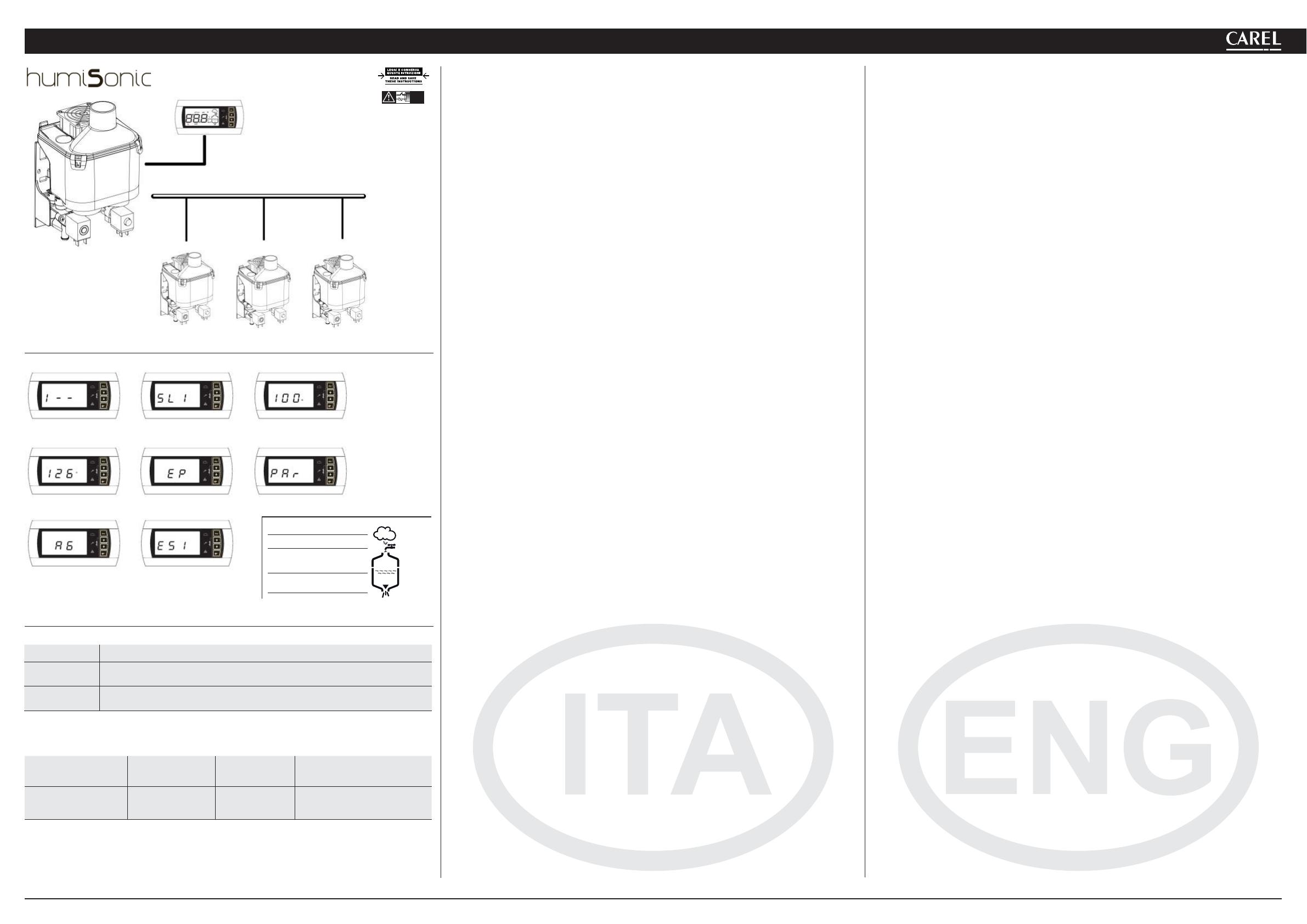
Fig. 1
Codice / Code Descrizione / Description
PU
Segnale di comando esterno non connesso
External Signal not connected
OFL
Supervisore sconnesso e Master in modalità richiesta da seriale
Supervisor unconnected and Master Unit with serial request enabled
Fig. 2 Fig. 3
Fig. 4 Fig. 5 Fig. 6
Fig. 7 Fig. 8
Tab.1
Bit 15
Modalità
Mode
Bit 13-14
Indirizzo slave
Slave Address
Bit 8-12
Tipo Variabile
Variable Type
Bit 0-7
Indirizzo Supervisione Carel
Carel Supervisor Address
0 = Lettura /
Reading
1 = Scrittura /
Writing
01 = Slave 1
10 = Slave 2
11 = Slave 3
00100 = Int.
01000 = Analog.
10000 = Dig.
Es.: 0000 1000 = 8
(scrittura) (slave 2) (var. intera) (P0 = indirizzo 48)
Es: 1 10 00100 0011 0000 = 1100010000110000 = 50224
(writing) (slave 2) (int.variable) (P0 = addr. 48)
Tab.2
Predisposizioni
L’unità Master (UU**F*A***) è in grado di controllare il funzionamento di un massimo di 3 unità Slave
(UU**F*0***) collegate tramite rete tLan.
Per le connessioni elettriche fare riferimento allo schema in fi g.10.
I dipswitches 1-3 dell’unità Master devono essere impostati tutti a OFF.
Ogni unità Slave deve essere opportunamente confi gurata tramite i seguenti dipswitches:
1: Impostare a ON per la conversione della porta seriale (M11) da RS485 a tLan.
2/3: Indirizzo Slave, come in fi g. 10 (vedere Cap. 4 del manuale cod. +0300056IT-EN).
Logica di controllo
L’unità Master controlla ogni unità Slave, ad esso collegata, attraverso i seguenti parametri:
• Abilitazione/Disabilitazione al funzionamento
• Livello della produzione dell’acqua nebulizzata
I segnali di comando (sonde/umidostato/regolatore esterno) vengono letti e gestiti solo dall’unità Master che
provvede poi a regolare il funzionamento degli Slave. Il livello di produzione del Master viene passato a tutti
gli Slave:
Es.1: Master confi gurato in regolazione proporzionale (vedi cap.4.4 del manuale) e richiesta al 90%:
Il Master e ogni Slave moduleranno il 90% della propria capacità (vedi cap. 13.3 del Manuale)
Es.2: Master confi gurato in regolazione sonda ambiente, setpoint 50%rH:
al raggiungimento del setpoint il Master e tutti gli Slave interromperanno la produzione di acqua nebulizzata.
Ogni unità (Master o Slave) è autonoma per quanto riguarda la logica di controllo della produzione di acqua
nebulizzata e di tutte le altre funzioni.
Gestione degli slave da terminale (master)
Da maschera principale premere il tasto PRG per 3 secondi e inserire la password 90
Il terminale visualizzerà lo stato degli Slave connessi secondo la seguente logica:
a partire dal digit di sinistra: Stato Unità 1, Stato Unità 2, Stato unità 3.
Il simbolo1 signifi ca “unità online”, mentre il simbolo -signifi ca “unità offl ine”.
Nella Fig.1 è portato l’esempio di Unità 1 online (Digit di sinistra a1) mentre Unità 2 e 3 offl ine (digit centrale
e di destra a -).
Premendo il tasto ENTER il terminale si porta nel menu di selezione dell’unità che si vuole controllare, con i tasti
UP e DOWN è possibile selezionare l’unità desiderata. In Fig.2 è mostrata la schermata di selezione dell’Unità 1.
Premendo ENTER si accede al menu di controllo dell’unità desiderata, con i tasti UP e DOWN si possono scor-
rere le seguenti visualizzazioni:
• Percentuale di richiesta passata dal Master (Fig.3).
• Contaore funzionamento (Fig.4), resettabile premendo UP+DOWN per 5 secondi (vedi parametro
d3
, cap.
7.4 del manuale cod. +0300056IT-EN).
• Allarmi unità (Fig.5, se assenti viene visualizzato --), resettabili premendo UP+DOWN per 5 secondi.
• Accesso menu confi gurazione parametri (Fig.6).
Le icone, in questa visualizzazione, indicano lo stato dello slave selezionato (Fig.9)
Premendo ENTER dalla schermata di accesso al menu confi gurazione parametri si accede alla lista parametri
che è possibile modifi care (Fig.7).
Per il signifi cato dei parametri fare riferimento al Cap. 7 del manuale cod. +0300056IT-EN.
Il parametro b8 è utilizzato come timeout per il riconoscimento di un’unità offl ine, secondo il numero di slave
collegati potrebbe essere necessario variare tale parametro, impostato per default a 10s.
Allarmi
Da maschera principale il Master visualizza la presenza di allarmi su un determinato slave con il codiceESX
Con X inteso come l’indirizzo dello slave che ha l’allarme attivo (Fig. 8, allarme slave 1).
Per il dettaglio dell’allarme in corso è necessario accedere al menu dello slave relativo.
Ogni Unità è autonoma nella gestione dei propri allarmi, ad eccezione di quelli riferiti ai segnali di comando
collegati al Master che inibiscono l’intera rete di umidifi catori (vedi Tab.1).
Controllo da supervisore (Carel/Modbus
)
Tramite le variabili di supervisione I62 e I63 (Modbus
189 e 190) è possibile visualizzare e impostare i parametri
degli slave.
La variabile I62 (Modbus 189) deve essere scritta come in Tab.2.
Se la variabile è richiesta in lettura il valore sarà presente nella variabile I63 (Modbus 190) dopo la scrittura di
I62, se la variabile è richiesta in scrittura il valore scritto sarà quello presente nella variabile I63, che deve quindi
essere precedentemente scritta.
Es: Scrittura del parametro P0 dello Slave 2 a 70
- Scrittura I63 a 70
- Scrittura I62 a 50224 (Vedi esempio di Tab.2)
Setup
The Master unit (UU**F*A***) is able to control the operation of a maximum of 3 Slave units (UU**F*0***) con-
nected via tLan network .
For electrical connections refer to diagram on page 10.
The Master unit’s dipswitches 1-3 must be all set to OFF.
Each slave unit must be properly confi gured via the following dipswitches:
1: Set to ON for the conversion of the serial port (M11) from 485 to tLan.
2/3: Slave address, as shown on page 2 (See Sect. 4 of Manual cod. +0300056IT-EN).
Control logic
The master unit controls each Slave unit, through the following parameters:
• Enable / Disable the operation
• Level of production of atomized water
The control signals (probes / humidistat / external regulator) are read and handled only by the Master who shall
then adjust the operation of the slave. The production level of the Master is passed to all the Slaves:
Es.1: Master confi gured proportional control (see cap.4.4 the manual) and 90% of request:
The master and each slave modulate 90% of its capacity (see Paragr.13.3 of manual cod. +0300056IT-EN).
ES.2: Master confi gured in the control room sensor, set point 50% rH:
The setpoint is reached the Master and all Slave interrupt the production of waterspray.
Each unit (Master or Slave) is autonomous as regards the control logic of the production of atomized water and
all the other functions.
Management of slave by terminal (master)
From the main screen press the PRG button for 3 seconds and enter the password 90
The terminal displays the status of slaves connected according to the following logic:
a digit from the left: Unit 1 Status, Unit 2 Status, Unit 3 Status.
The symbol 1 means "online unit" and the symbol -means "unit offl ine".
In Fig.1 is the example of online Unit 1 (left Digit to1) while Unit 2 and 3 Offl ine(middle digit and the right to -).
Pressing the ENTER key on the terminal goes into the selection menu of the drive you want to check with the
UP and DOWN to select the desired unit. Fig.2 shows the selection screen of Unit 1.
Press ENTER to access the control menu of the desired unit, with UP and DOWN you can scroll through the
following views:
• Percentage of demand from the master (Fig. 3).
• Operating hour counter (Fig. 4), resettable by pressing UP + DOWN for 5 seconds (see parameter d3, Sect.
7.4 of manual - cod. +0300056IT-EN).
• Units alarms (Fig. 5, if absent
--is displayed), can be reset by pressing UP + DOWN for 5 seconds.
• Access to confi guration parameters menu (Fig. 6).
In this view, the icons show the status of the selected unit (Fig.9)
Press ENTER at the login screen of the confi guration parameters menu to access the list of parameters (Fig. 7).
For the meaning of the parameters, refer to Sect. 7 of manual cod. +0300056IT-EN.
Parameter b8 is used as a timeout for the recognition of a unit offl ine.
According to the number of connected slaves it may be necessary change this parameter (default is 10 seconds).
Alarms
From the main screen, the Master displays the presence of alarms, of a given slave, trough the code ESX
With X meant as the slave address that the alarm is active (Fig. 8, alarm slave 1).
For details of the alarm being you must enter the menu on the slave.
Each unit is autonomous in managing their alarms, except those related to control signals connected to the
Master that inhibit the entire network of humidifi ers (See table 1)
Control via Supervisor (Carel/Modbus
)
Using supervision variables I62 and I63 (Modbus 189 and 190) you can view and set the parameters of the slave.
The variable I62 (Modbus 189) must be written as in Table 2.
If the variable is required for reading the value will be present in the variable I63 (Modbus 190) after writing
the I62, if the variable is required for writing, the value written will be present in the variable I63, which must
be written fi rst.
Ex: Write the parameter P0 Slave 2 to 70
- Writing 70 into I63
- Writing 50224 into I62 (See Table 2 for example)
Produzione/Production
Carico/Fill
Presenza acqua/
Water presence
Scarico/Drain
Fig. 9
NO POWER
& SIGNAL
CABLES
TOGETHER
READ CAREFULLY IN THE TEXT!
