La pagina si sta caricando...

powerSplit
Manuale d’uso
User manual
LEGGI E CONSERVA
QUESTE ISTRUZIONI
READ AND SAVE
THESE INSTRUCTIONS


Vogliamo farvi risparmiare tempo
e denaro!
Vi assicuriamo che la completa lettura
di questo manuale vi garantirà una
corretta installazione ed un sicuro
utilizzo del prodotto descritto.
AVVERTENZE IMPORTANTI
PRIMA DI INSTALLARE O INTERVENIRE
SULL’APPARECCHIO, LEGGERE ATTENTAMENTE E
SEGUIRE LE ISTRUZIONI CONTENUTE IN QUESTO
MANUALE.
Questa apparecchiatura è stata costruita per
funzionare senza rischi per gli scopi prefissati
purché:
• l’installazione, la conduzione e la manutenzione siano
eseguite secondo le istruzioni contenute in questo
manuale;
• le condizioni dell’ambiente e della tensione di
alimentazione rientrino tra quelle specificate.
Ogni utilizzo diverso da questo e l’apporto di
modifiche, non espressamente autorizzate dal
costruttore, sono da intendersi impropri.
La responsabilità di lesioni o danni causati da uso
improprio ricadrà esclusivamente sull’utilizzatore.
Si osservi che questa macchina contiene componenti
elettrici sotto tensione e quindi tutte le operazioni di
servizio o manutenzione devono essere condotte da
personale esperto e qualificato, cosciente delle
necessarie precauzioni.
Prima di accedere alle parti interne sezionare la
macchina dalla rete elettrica.
Smaltimento delle par
ti del controllore
Il controllore è composto da parti in metallo e da parti in
plastica.Tutte queste parti vanno smaltite secondo le
Normative locali in materia di smaltimento.
Pulizia del controllore
Utilizzare esclusivamente detergenti neutri ed acqua.
We wish to save you time and
money!
We can assure you that a thorough
reading of this manual will guarantee
correct installation and safe use of the
product described.
IMPORTANT
BEFORE INSTALLING OR OPERATING ON THE
DEVICE, CAREFULLY READ THE INSTRUCTIONS IN
THIS MANUAL.
This instrument has been designed to operate without
risks only if:
• installation, operation and maintenance are performed
according to the instructions of this manual;
•environmental conditions and supply voltage fall within
the values indicated here below.
Any different use or changes which have not been
previously authorised by the manufacturer, are
considered improper.
Responsibility for injures or damage caused by
improper use will fall exclusively on the user.
Warning:voltage is present in some electrical
components of this instrument, thus all the service
or maintenance operations must be performed by
expert and skilled personnel only, aware of the
necessary precautions to be taken.
Before accessing the internal parts, disconnect the
power supply.
Disposing of the par
ts of the controller
The controller is made from metal parts and plastic parts.
All these parts should be disposed of according to local
standards on waste disposal.
Cleaning the contr
oller
Only use neutral detergents and water.
LEGGI E CONSERVA
QUESTE ISTRUZIONI
READ AND SAVE
THESE INSTRUCTIONS


Indice:
1. INTRODUZIONE: CARATTERISTICHE GENERALI 3
1.1 Modelli disponibili 3
1.2 Caratteristiche 3
2. ARCHITETTURA HARDWARE 4
2.1 Significato degli ingressi ed uscite 4
2.2 Codici degli strumenti ed accessori 6
2.3 Interfaccia utente 8
3. Installazione 10
3.1 Dimensioni e montaggio 10
3.2 Collegamenti elettrici 11
3.3 Impostazione dei principali parametri di configurazione 11
3.4 Configurazione della LAN 11
3.5 Configurazione del sistema e principali funzioni 13
3.6 Funzionalità di rete locale (LAN) 14
3.7 Funzioni HACCP 16
4. Descrizione dei parametri di configurazione 18
4.1 Classificazione dei parametri 18
4.2 / = parametri relativi alla gestione delle sonde di temperatura 19
4.3 A = parametri per la gestione degli allarmi 21
4.4 c = parametri per la gestione del compressore 25
4.5 d = parametri per la gestione dello sbrinamento 28
4.6 F = parametri per la gestione delle ventole dell'evaporatore 31
4.7 H = altre predisposizioni 32
4.8 L = Parametri gestione sensore luce 33
4.9 r = parametri relativi alla regolazione della temperatura 34
4.10 I/S = Parametri LAN 36
4.11 t = Parametri per HACCP, orologio e Defrost temporizzato 36
5. Stati di funzionamento 38
5.1 Stato di ON/OFF del PSB 39
5.2 Esempi d’uso dell’ingresso digitale virtuale. 40
6. Parametri - Tabella Riassuntiva 41
7. ALLARMI e ricerca guasti 45
7.1 Codici di allarme e segnalazioni 45
7.2 Note sugli allarmi 46
7.3 Ricerca ed eliminazione dei problemi 46
8. Caratteristiche tecniche controlli PSB 49
9. Accessori 51
9.1 Chiave copia parametri 51
9.2 Copia e scarico parametri 51
9.3 Segnalazione errori 52
9.4 Caratteristiche tecniche Chiave PSOPZKEY 52
Index:
1. INTRODUCTION:GENERAL CHARACTERISTICS 3
1.1 Models available 3
1.2 Characteristics 3
2. HARDWARE STRUCTURE 4
2.1 Meaning of the inputs and outputs 4
2.2 Instrument and accessory codes 6
2.3 User interface 8
3. Installation 10
3.1 Dimensions and mounting 10
3.2 Electrical connections 11
3.3 Setting the main configuration parameters 11
3.4 LAN configuration 11
3.5 System configuration and main functions 13
3.6 Local network (LAN) functions 14
3.7 HACCP functions 16
4. Description of the configuration parameters 18
4.1 Classification of the parameters 18
4.2 / = temperature probe management parameters 19
4.3 A = Alarm management parameters 21
4.4 c = Compressor management parameters 25
4.5 d = Defrost management parameters 28
4.6 F = Evaporator fan management parameters 31
4.7 H = other settings 32
4.8 L = Light sensor management parameters 33
4.9 r = Temperature control parameters 34
4.10 I/S = LAN parameters 36
4.11 t = HACCP, clock and timed defrost parameters 36
5. Operating modes 38
5.1 PSB ON/OFF mode 39
5.2 Examples on using the virtual digital input. 40
6. Parameters - Summary Table 41
7. ALARMS and troubleshooting 45
7.1 Alarm codes and signals 45
7.2 Notes on the alarms 46
7.3 Troubleshooting 46
8. Technical specifications, PSB controllers 49
9. Accessories 51
9.1 Parameter copy key 51
9.2 Copy and download parameters 51
9.3 Errors signals 52
9.4 Technical specifications, PSOPZKEY key 52


3
powerSplit manual - cod.+030220320 rel. 1.1 - 09/12/02
1. Introduzione: Caratteristiche generali
1.1 Modelli disponibili
I prodotti PSB sono controlli elettronici integrati per banchi e celle
frigo, anche canalizzati, con gestione dei comandi base:
compressore, defrost, ventilatori ed anche per luce; antiappannamento
e gestione allarmi.
L' interfaccia operatore prevista è con i terminali locali, nelle versioni a
pannello PJ SMALL e LARGE, o con il terminale specifico per celle,
PST MASTER CELLA.
Sono previste le seguenti versioni per la scheda di potenza:
• alimentazione 230Vac
• modelli 4 o 6 relè
• modelli con orologio RTC settimanale
• predisposizione per interfaccia seriale di supervisione (RS485)
opzionale, installabile su tutti i modelli
• codice specifico per le celle con terminale remotabile (RS485) fino
a 500 m
1.2 Caratteristiche
•Tre ingressi sonda NTC:regolazione, defrost, prodotto (denominate
anche S1, S2, S3).
• Due ingressi digitali multifunzione ed un ingresso per sensore
presenza luce (apertura porta)
• Realizzazione quadro elettrico di macchina sulla scheda, con
connessione diretta dei carichi
• Comando per compressore fino a 2 HP e luci fino a 1000 VA max
(16x50 W neon)
• Gestione banchi canalizzati fino a 6 unità con sincronismo defrost
ed attuazioni (mediante LAN).
•Terminale utente collegabile fino a 10 m (500 m in versione per celle)
1. Introduction: General characteristics
1.1 Models available
The PSB products are built-in electronic controllers for showcases and
cold rooms, including multiplexed showcases, with management of the
basic:compressor, defrost, fan functions, as well as light;demist and
alarm management.
The user interface involves local terminals, in the PJ SMALL and
LARGE panel versions, or the specific PST MASTER CELLA terminal
for cold rooms.
The following versions are available for the power board:
• 230Vac power supply
• models with 4 or 6 relays
• models with weekly RTC clock
• ready for the installation of the optional, serial supervisor interface
(RS485), all models
• specific model for cold rooms with remote terminal (RS485),
installable at distances of up to 500m
1.2 Characteristics
• Three NTC probe inputs:control, defrost, product (also called S1,
S2, S3).
• Two multi-function digital inputs and one input for light sensor (door
opening)
• Wiring of the machine’s electrical panel on the board, with direct
connection of the loads
• Control of compressors of up to 2 HP, and lights of up to 1000VA max
(16x50W neon)
• Management of multiplexed showcases of up to 6 units, with
synchronised defrost and actuations (by LAN).
• User terminal with remote installation at up to 10m (500m for the
cold room version)

4
powerSplit manual - cod.+030220320 rel. 1.1 - 09/12/02
2. Architettura hardware
2.1 Significato degli ingressi ed uscite
2.1.1 Alimentazione
• Ingresso alimentazione da rete su tre morsetti a vite, con capacità di
corrente 30 A max
• Tensione di alimentazione a seconda del modello: 230 Vac - 115 Vac
- 24 Vac, 50/60 Hz
• Utilizzo con cavi di sezione da 0,5 a 4 mm
2
(cavo flessibile)
• Morsetti faston di appoggio per connessione carichi:6 morsetti per L,
N e Terra.
Morsetto L:Linea 250 Vac max 30A max
Morsetto N:Neutro 250 Vac max 30A max
Morsetto :Terra 30 A max
Faston L (x6): Linea morsetti faston 16 A max per contatto
Faston N (x6): Neutro morsetti faston 16 A max per contatto
Faston (x6):Terra morsetti faston 16 A max per contatto
2.1.2 Uscite relè
• contatti relè isolati con morsetti faston 6,3 mm capacità di corrente
16 A max
• isolamento principale tra contatti di relè diversi, disconnessione
ridotta sul contatto relè
• utilizzo con contatti faston femmina (6,3 mm) con cavi da 1,5 a 2,5 mm
2
.
• cablaggio connessioni mediante i faston di alimentazione con ponti
(cavo 2,5 mm
2
con terminazioni faston femmina lunghezza 10-15 cm)
uno per ogni uscita.
2. Hardware structure
2.1 Meaning of the inputs and outputs
2.1.1 Power supply
• Mains power supply connection using three screw terminals, with max
current rating 30A
• Power supply voltage according to the model: 230Vac - 115Vac -
24Vac, 50/60 Hz
• Cable cross-sections from 0.5 to 4 mm
2
(flexible cables)
• Faston terminals for connecting the loads:6 terminals for L, N and
Earth.
Te rminal L: Line 250Vac max 30A max
Te rminal N: Neutral 250Vac max 30A max
Te rminal : Earth 30A max
Faston L (x6): Line terminals faston 16A max per contact
Faston N (x6): Neutral terminals faston 16A max per contact
Faston (x6):Earth terminals faston 16A max per contact
2.1.2 Relay outputs
• insulated relay contacts with faston terminals 6.3mm, max.current
rating 16A
• primary insulation main between the contacts of different relays
• connect to female faston contacts (6.3mm), with wires from 1.5 to 2.5
mm
2
.
• wiring connections using the power supply fastons with jumpers
(2.5 mm
2
wires with female faston terminals, length 10-15cm), one
for each output.
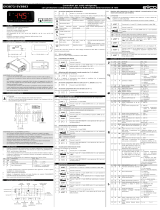
Connessioni interne di alimentazione consigliate
Suggested inside power connections
16A 2HP10A10A16A
RS 485
optional board
Connection to
LAN
Local Area Network
RS485
Connection to
Supervisor
T Products
S3
Power (green)
RX/TX
GND
GND
RX/TX+
RX/TX-
GND (red)
RX/TX (white)
GND (yellow)
T Defrost
S2
T Ambient
S1
Digital Input 1
Digital Input 2
Photo Res.
15 16 17 18 19 20 21 22 23 24 25 26 27 28 29 30 31 32 33 34 35
PROG.
KEY
(12Vdc)
(24Vdc)
L
N
Power Supply
230 Vac (30A max)
10A
PSBoard
-10T50
PST Small/Large
Terminale e/o Visualizzatore
Terminal and/or Display units
PSTCONxxxx
TO I/O
BOARD
1
2
3
Comp.DefrostFanAlarm AUX 2
AUX
AUX 1
Lux
AUX
up-to
10m
1
2
35
4
6
7
8
9
1012
11
13
14
P*
Fig. 2.1.1

5
powerSplit manual - cod.+030220320 rel. 1.1 - 09/12/02
Faston 1: C relè compressore 250 Vac 16 A 2 Hp max
Faston 2: NO relè compressore
Faston 3: C relè defrost 250 Vac 16 A res. max
Faston 4: NC relè defrost
Faston 5: NO relè defrost
Faston 8: C relè ventilatori 250 Vac 10 A res.(2 A) max
Faston 9: NO relelè ventilatori
Faston 13:C relè aux1/luce 250 Vac 16 A res.500W-1000VA max
Faston 14: NO relè aux1/luce
Faston 6: C relè aux2/antiapp. 250 Vac 10 A res.(2 A) max
Faston 7: NO relè aux2/antiapp.
Faston 10: C relè allarme 250 Vac 10 A res. (2 A) max
Faston 11: NC relè allarme
Faston 12: NO relè allarme
2.1.3 Ingressi sonde NTC
• ingressi di misura per sonde NTC standard Carel (10 Kohm a 25 ˚C)
• compatibilità con misura PLUG IN, misura da -50 a +90 ˚C
• filtro ingresso 1mS (disturbi veloci, burst), la misura è filtrata SW con
media (/2 da 0,1 a 2s circa)
• connessione con morsetti fissi a vite per filo da 0,5 a 1,5 mm
2
.
• distanza max 30 m per compatibilità normative (surge)
Morsetto 24:ingresso segnale NTC sonda regolazione (ambiente)
(-50/+90˚C )
Morsetto 25:riferimento segnale NTC sonda regolazione
Morsetto 26:ingresso segnale NTC sonda defrost (-50/+90˚C)
Morsetto 27:riferimento segnale NTC sonda defrost
Morsetto 28:ingresso segnale NTC sonda prodotto/defrost 2 (-50/+90˚C)
Morsetto 29:riferimento segnale NTC sonda prodotto/defrost 2
2.1.4 Ingressi digitali
• ingressi da contatto pulito (non alimentato) con corrente di chiusura
8-12 mA
• filtro ingresso 1mS (disturbi veloci, burst), il segnale è filtrato SW
media a 240mS
• connessione con morsetti fissi a vite per filo da 0,5 a 1,5 mm
2
.
• distanza max 30 m per compatibilità normative (surge)
Morsetto 31:ingresso digitale 1
Morsetto 30:riferimento ingresso digitale 1
Morsetto 33:ingresso digitale 2
Morsetto 32:riferimento ingresso digitale 2
Note:
l'utilizzo degli ingressi è programmabile da parametri (ingresso
multifunzione)
2.1.5 Ingresso sensore presenza luce
• ingresso da fotoresistenza per segnalare l'apertura delle porte in
armadi refrigerati, uno o due sensori previsti
• connessione con morsetti fissi a vite (2 vie) per filo da 0,5 a 1,5 mm
2
.
• Distanza massima 30 metri, per compatibilità normative (surge).
Morsetto 34:riferimento (comune) fotoresistenze
Morsetto 35:ingresso fotoresistenze (presenza luce)
Nota:
è disponibile un solo ingresso con la possibilità di collegare uno
o due sensori in parallelo
Faston 1: C compressor relay 250Vac 16A 2 HP max
Faston 2: NO compressor relay
Faston 3: C defrost relay 250Vac 16A res.max
Faston 4: NC defrost relay
Faston 5: NO defrost relay
Faston 8: C fan relay 250Vac 10A res.(2A) max
Faston 9: NO fan relay
Faston 13:C aux1/light relay 250Vac 16A res.500W-1000VA max
Faston 14: NO aux1/light relay
Faston 6: C aux2/demist relay 250Vac 10A res.(2A) max
Faston 7: NO aux2/demist relay
Faston 10: C alarm relay 250Vac 10A res.(2A) max
Faston 11: NC alarm relay
Faston 12: NO alarm relay
2.1.3 NTC probe inputs
• measurement inputs for standard Carel NTC probes (10Kohm at 25 ˚C)
• compatibility with PLUG IN measurements, measuring range from
-50 to +90 ˚C
• 1mS input filter (fast transients, burst)
• connection with fixed screw terminals for wires from 0.5 to 1.5 mm
2
• distance max 30m for standards compliance (surge)
Te rminal 24: NTC control probe (ambient) input signal (-50/+90˚C)
Te rminal 25: NTC control probe reference signal
Te rminal 26: NTC defrost probe input signal (-50/+90˚C)
Te rminal 27: NTC defrost probe reference signal
Te rminal 28: NTC product/defrost2 probe input signal (-50/+90˚C)
Te rminal 29: NTC product/defrost2 probe reference signal
2.1.4 Digital inputs
• inputs from free contacts (not supplied) with closing current of 8-12mA
• 1mS filter input (fast transients, burst)
• connection with fixed screw terminals for wires from 0.5 to 1.5 mm
2
.
• distance max 30m for standards compliance (surge)
Te rminal 31: digital input 1
Te rminal 30: digital input 1 reference
Te rminal 33: digital input 2
Te rminal 32: digital input 2 reference
Note:
The use of the inputs can be programmed by setting the corre-
sponding parameters (multi-function inputs)
2.1.5 Light presence sensor input
• input from photocell to signal the opening of the doors on
refrigerated display cabinets, one or two sensors featured
• connection with fixed screw terminals (2-way) for wire cross-sections
from 0.5 to 1.5 mm
2
.
• Maximum distance 30 metres for standards compatibility (surge).
Te rminal 34: photocell reference (common)
Te rminal 35: photocell input (light presence)
Note:
One input only is available, with the possibility of connecting one
or two sensors in parallel

6
powerSplit manual - cod.+030220320 rel. 1.1 - 09/12/02
2.1.6 Connessione terminale
• connessione con alimentazione del terminale PST "Small" o "Large"
PSTxxL
• alimentazione da tensione livellata 20 - 35 Vdc (0,7 W max 50 mA)
protetta da PTC fuse 100 - 140 mA
• velocità seriale prevista 4800 bit/S
• connessione a quattro fili con cavo non schermato AWG28, distanza
max 10 m;per connessione RS485 utilizzare cavi (alimentazione)
con sezione adeguata alla distanza
Morsetto 20:alimentazione terminale +VL (8-35 Vdc)
Morsetto 21:riferimento alimentazione GND
Morsetto 22:segnale Tx/Rx (intf.transistor, livelli TTL)
Morsetto 23:riferimento GND
Per connessione di terminali diversi da PST Large o Small, mediante
interfaccia RS485, le connessioni cambiano come segue:
Morsetto 20:alimentazione terminale +VL (non collegare)
Morsetto 21:riferimento alimentazione GND
Morsetto 22:segnaleTX/RX- RS485
Morsetto 23:segnaleTX/RX+ RS485
Nota:
per i terminali tipo MasterCella l’alimentazione viene fornita
separatamente.
2.1.7 Connessione seriale LAN
• connessione in rete verso altri controlli PJ power MGE (non
supervisione) lung. max 10 m
• velocità seriale prevista 19200 bit/S (default) oppure 9600 bit/S.
Morsetto 18:riferimento alimentazione e segnale GND
Morsetto 19:segnale Tx/Rx (intf.transistor, livelli TTL)
2.1.8 Connettore opzione seriale RS485
Connettore per collegamento scheda opzionale con driver RS485 per
interfacciamento con supervisore
• pin-strip 8 vie con fissaggio scheda mediante asole (saldabile a CS)
per scheda opzione seriale
• velocità seriale prevista 9600-19200 bit/S
• connessione a 3 morsetti a vite fissi (GND, Tx/Rx+, Tx/Rx-)
Morsetto 15:segnale Tx/Rx - (RS485)
Morsetto 16:segnale Tx/Rx + (RS485)
Morsetto 17:riferimento segnale GND
2.1.9 Connettore chiave programmazione
Connessione per chiave di copia parametri con alimentazione diretta
5 Vdc (max 30 mA)
• funzionamento con controllo spento, alimentato da chiave.
• interfaccia seriale di tipo i2c bus con connessione diretta a
microprocessore e memoria interna (non utilizzabile per altre
connessioni)
• connettore a 4 vie standard PLUG IN con segnali:+5V, GND, I2Clk,
I2Dat.
2.2 Codici degli strumenti ed accessori
2.2.1 Controllo PJ Power 4/6 relè 3 sonde NTC
Tabella. 2.2.1
2.1.6 Terminal connection
• connection with power supply for the PST "Small" and PSTxxL
"Large" terminals
• 20 - 35Vdc “clamped” voltage power supply (0.7W max 50mA)
protected by 100 - 140 mA PTC fuse
• serial speed 4800 bit/S
• four-wire connection using non-shielded AWG28 cable, max distance
10m;for the RS485 connection use cables (power supply) with a
suitable cross-section for the distance
Te rminal 20: terminal power supply +VL (8-35Vdc)
Te rminal 21: power supply GND
Te rminal 22:Tx/Rx signal (transistor intf., TTL levels)
Te rminal 23: GND
To connect terminals other than the PST Large or Small, using the
RS485 interface, the connections change as follows:
Te rminal 20: terminal power supply +VL (do not connect)
Te rminal 21: power supply GND
Te rminal 22:TX/RX- signal RS485
Te rminal 23:TX/RX+ signal RS485
Note:
for the MASTERCELLA terminals, the power supply is connected
separately.
2.1.7 LAN serial connection
• network connection to other PJ power MGE controllers (not
supervisor) max length 10m
• serial speed 19200 bit/S (default) or 9600 bit/S.
Te rminal 18: power supply and signal GND
Te rminal 19:Tx/Rx signal (transistor intf., TTL levels)
2.1.8 RS485 serial connector option
Optional connector for card with RS485 driver for supervisor interface
• 8-way pin-strip with slotted card for serial option
• serial speed 9600-19200 bit/S
• connection by 3 fixed screw terminals (GND, Tx/Rx+, Tx/Rx-)
Te rminal 15:Tx/Rx - signal (RS485)
Te rminal 16:Tx/Rx + signal (RS485)
Te rminal 17: signal GND
2.1.9 Programming key connector
Connector for the key used to copy the parameters, with direct 5Vdc
power supply (max 30 mA)
• operation when the controller is off, powered by the key
• i2c-bus serial interface with direct connection to the microprocessor
and internal memory (cannot be used for other connections).
• standard 4-way PLUG IN connector with the following signals:+5V,
GND, I2Clk, I2Dat.
Alimentazione Opzioni
CODICI MODELLI 230 115 24 6 Relè 4 Relè RTC RS485 Descrizione
PSB0000000 • • x PS 4 relè 3 NTC senza RTC
PSB0001000 • • • x PS 4 relè 3 NTC con RTC
PSB0000100 • • x PS 6 relè 3 NTC senza RTC
PSB0001100 • • • x PS 6 relè 3 NTC con RTC
A
vvetenza: Il simbolo “x”indica una funzione disponibile se viene installata l'opzione relativa.

7
powerSplit manual - cod.+030220320 rel. 1.1 - 09/12/02
2.2.2 Versioni a 4 Relè PSB000000
Questo modello presenta quattro relè per le seguenti funzioni:
COMPRESSORE, DEFROST, FAN, AUX1/LUCE.
Le uscite ALARM e AUX2 non sono abilitate e non sono montati i
relativi componenti (Relè e connessioni).
2.2.3 Versioni con RTC (real-time clock)
Queste versioni offrono un orologio interno per gestire lo sbrinamento
ad orari programmati (6 eventi max.) e la registrazione degli allarmi
HACCP. L'orologio viene utilizzato nel formato dd :hh :mm :ss
(giorno-settimana: ora :minuto :secondo).Il mantenimento dei dati e
avanzamento dell'orologio è garantito da una batteria ricaricabile con
autonomia di circa 6 mesi (da carica completa).
2.2.4 Terminali a pannello
Per l'elenco completo dei codici e le relative funzioni vedere la
documentazione.
2.2.5 Scheda opzione seriale RS485 FCSER00000
Scheda opzionale che permette la connessione del controllo
PowerSplit alla rete di supervisione RS485, fino a 199 preiferiche.
Nota:
la connessione avviene mediante un pin-strip 8 vie.
Sulla scheda PSB può essere presente un pin-strip a 10 vie, in questo
caso assicurasi di fare coincidere la posizione della asola presente su
PSB con la chiave di polarizzazione presente sulla scheda FCSER00000.
2.2.6 Chiave di programmazione PSOPZKEY00
Questa chiave hardware opzionale che permette di memorizzare e
duplicare la configurazione dei parametri dei controlli Power-Split.
• Copia dei parametri da controllo verso chiave e viceversa
• Controllo codice, modello e revisione per evitare copie incompatibili
• Segnalazione esecuzione copia con LED bicolore rosso/verde
2.2.7 Contenitore PSOPZBOX00
Contenitore standard da quadro IP55 con passacavi dim.240x190x90
mm completo di piastra per il fissaggio ed accessori (viti, distanziali,
bloccacavi).
2.2 Instrument and accessory codes
2.2.1 PJ Power controller with 4/6 relays, 3 NTC probes
Table 2.2.1
2.2.2 Versions with 4 RELAYS PSB000000
This model has four relays for the following functions:
COMPRESSOR, DEFROST, FAN, AUX1/LIGHT.
The ALARM and AUX2 outputs are not enabled, and the corresponding
components are not fitted (relays and connections).
2.2.3 Versions with RTC (real-time clock)
These versions feature an internal clock to manage the defrosts at set
times (max.6 events) and the saving of the HACCP alarms.
The clock uses the format dd:hh:mm:ss (weekday: hours:minutes:
seconds).The data and the time are stored using a rechargeable
battery, with an autonomy of around 6 months (when completely
charged).
2.2.4 Panel terminals
For the complete list of codes and the corresponding functions, see
the specific document
2.2.5 FCSER00000 RS485 serial card option
Optional board that allows the PowerSplit controller to be connected to
the RS485 supervisor network, up to 199 peripherals.
Note:
the connection is made using an 8-way pin-strip.
The PSB board may have a 10-way pin-strip, and in this case make
sure that the position of the slot on the PSB coincides with the
polarisation key on the FCSER00000 board.
2.2.6 PSOPZKEY00 programming key
This optional hardware key is used to save and copy the
configuration of the parameters for the Power-Split controllers.
• Copies the parameters from the controller to the key and vice-versa
• Checks the code, model and revision to avoid incompatible copies.
• Signals the status using a two-colour LED (red/green.
2.2.7 PSOPZBOX00 container
Standard container for IP55 panels with 240x190x90 mm fairleads,
complete with fastening plate and accessories (screws, spacers, cable
clamps).
Power supply Options
MODEL CODES 230 115 24 6 RELAY 4 RELAY RTC RS485 Description
PSB0000000 • • x PS with 4 relays, 3 NTC without RTC
PSB0001000 • • • x PS with 4 relays, 3 NTC and RTC
PSB0000100 • • x PS with 6 relays, 3 NTC without RTC
PSB0001100 • • • x PS with 6 relays, 3 NTC and RTC
W
arning: The “x”symbol indicates that the function is available if the corresponding option is installed.
Oggetto Codice Funzioni
Visualizzatore SMALL rosso PST00VR100 Ntc , LED 3 digit
Ter minale SMALL rosso PST00SR300 Buzzer, Infrared, Ntc, Ingressi digitali, LED 3 digit
Ter minale LARGE rosso PST00LR200 Buzzer, Infrared , LED 4 digit
Cavi di collegamento PSTCON0300 3m
PSTCON1000 10m
Flangia di montaggio per PST SMALL PSTFS***** (S1,..S4) Flangia normale o con foratura per tasti e segnalazioni
Flangia di montaggio per PST LARGE PSTFL*****
Object Code Functions
SMALL red display PST00VR100 NTC, 3 digit LED
SMALL red terminal PST00SR300 Buzzer, Infrared, NTC, Digital inputs, 3 digit LED
LARGE red terminal PST00LR200 Buzzer, Infrared, 4 digit LED
Connection cables PSTCON0300 3m
PSTCON1000 10m
Assembly flange for PST SMALL PSTFS***** (S1,..S4) Normal flange or with holes for buttons and signals.
Assembly flange for PST LARGE PSTFL*****

8
powerSplit manual - cod.+030220320 rel. 1.1 - 09/12/02
2.2.8 Sensore presenza luce PSOPZLHT00
Fotoresistenza incapsulata in terminale plastico trasparente, con cavo
di connessione 3 metri.
2.2.9 Kit programmazione parametri
Permette di leggere e modificare i parametri memorizzati in una chiave
di programmazione (PSOPZKEY00).
2.3 Interfaccia utente
I terminali e visualizzatori previsti sono i modelli "LARGE" e "SMALL"
(codici PSTxx).Sono disponibili anche altri modelli, ad esempio il ter-
minale per celle per i quali si rimanda alla relativa doumentazione.
2.3.1 Funzioni Tasti e Led Terminale PJ Large
Tasto “1” (LED rosso)
Funzionamento nor
male
• premuto per 5 sec.resetta allarme HACCP
(HA o HF) se attivo
LED
• acceso fisso - Allarme HACCP per superamento
soglia e tempi (allarme HA)
• Lampeggiante continuo - Allarme HACCP per
superamento soglia e tempi dopo mancanza di
alimentazione (allarme HF)
Tasto “2” (LED giallo)
Funzionamento nor
male
• Premuto per 1 sec.attiva/disattiva uscita relè aux1 (luce)
LED
• Acceso fisso - Uscita relè aux1 (luce) attiva
Tasto “3” (LED verde)
Funzionamento nor
male
• Premuto per 5 sec.ON/OFF unità.
LED
• Acceso fisso - Regolazione in funzione
Nota: la funzione ON/OFF dipende da un param. di abilitazione (se non
abilitato, il controllo è sempre ON), il LED visualizza comunque lo stato.
Tasto “4” (LED giallo)
Funzionamento nor
male
• Premuto per 1 sec.attiva/disattiva uscita relè aux2
LED
• Acceso fisso - Uscita relè aux2 attiva
Tasto “5” (LED verde)
Funzionamento nor
male
• Premuto per 5 sec.attiva il ciclo continuo (dopo la pressione per 5 sec).
LED
• Acceso fisso - Ciclo continuo inserito.
Tasto “6” (LED verde)
Funzionamento normale
• ON/OFF luce dopo 1 sec.di pressione.
• premuto assieme al tasto 7 per 5 sec.attiva il ciclo continuo
Modifica parametri
• Passa da un parametro al successivo.
• Incrementa il valore associato al parametro visualizzato.
LED
• Stabilmente acceso - Compressore in funzione
• Lampeggiante continuo - Richiesta di attivazione compressore
(richiesta freddo)
2.2.8 PSOPZLHT00 light presence sensor
Photocell housed in a transparent plastic terminal, with 3m connection
cable.
2.2.9 Parameter programming kit
Used to read and modify the parameters saved on a programming key
(PSOPZKEY00).
2.3 User interface
The terminals and displays featured are the "LARGE" and "SMALL"
models (codes PSTxx).Other models are available, for example, the
terminal for cold rooms, please refer to the corresponding documents.
2.3.1 Function buttons and LEDs,PJ Large
terminal
Button “1” (red LED)
Nor
mal operation
• pressed for 5 seconds resets the HACCP
alarms (HA or HF) if active
LED
• On steady - HACCP alarm signalling the
exceeding of the threshold and times (HA alarm)
• Continuous flashing - HACCP alarm signalling the
exceeding of the threshold and times after power failure
(HF alarm)
Button “2” (yellow LED)
Nor
mal operation
• Pressed for 1 seconds activates/deactivates the aux1 relay output (light)
LED
• On steady - aux1 relay output (light) active
Button “3” (green LED)
Nor
mal oper
ation
• Pressed for 5 seconds unit ON/OFF.
LED
• On steady - Controller on
Note: the ON/OFF function depends on an enabling param.(if not enabled,
the controller is always ON), the LED in any case displays the status.
Button “4” (yellow LED)
Nor
mal operation
• Pressed for 1 seconds activates/deactivates the aux2 relay output
LED
• On steady - aux2 relay output active
Button “5” (green LED)
Nor
mal operation
• Pressed for 5 sec.starts the continuous cycle (after pressing for 5 sec.).
LED
• On steady - Continuous cycle on.
Button “6” (green LED)
Nor
mal operation
• Light ON/OFF when pressed for 1 sec.
• pressed together with the 7 button for 5 sec.active the continuous cycle
P
arameter modification
• Moves from one parameter to the next.
• Increases the value of the parameter displayed.
LED
• On steady - Compressor on
• Continuous flashing - Request for compressor activation (cooling
request)
1
2 4 6
8
3
5 7
Fig. 2.3.1.1

9
powerSplit manual - cod.+030220320 rel. 1.1 - 09/12/02
Tasto “7” (LED giallo)
Funzionamento nor
male
• Premuto per 5 sec attiva uno sbrinamento manuale, se presenti le
condizioni.
Modifca par
ametri
• Passa da un parametro al precedente.
• Diminuisce il valore associato al parametro visualizzato.
LED
• Acceso fisso - Sbrinamento in funzione
• Lampeggiante continuo - sbrinamento pendente.
Tasto “8” (LED rosso)
Funzionamento nor
male
• Tacita allarme acustico, se attivo.
• Premuto per 1 sec.visualizza e/o imposta il set point
• Premuto per più di 5 sec, non in presenza di allarme, dà accesso
al menù dei parametri di tipo F (frequenti)
• Premuto all’accensione del controllo assieme al tasto 7 esegue il
reset dei parametri (ripristino parametri di default)
Modifica par
ametri
• Visualizza il valore del parametro selezionato/esce dalla visualizzazione.
• Premuto per 5 sec esegue la memorizzazione permanente delle
modifiche.
LED
• acceso fisso - allarme attivo.
2.3.2 Elenco funzioni Tasti e Led Terminale PJ Small
Sono presenti solo tre tasti e tre LED degli otto sopra
elencati:6, 7 e 8.
Le funzioni per la modifica parametri sono le stesse già
descritte sopra per il terminale LARGE; per la regolazione
sono previste le funzioni di Ciclo Continuo, Defrost ON-OFF
luce e tacitazione allarmi:
Tasto “6” (LED verde)
Funzionamento nor
male
• ON/OFF luce dopo 1 sec.di pressione.
• Premuto assieme al tasto 7 per 5 secondi attiva il ciclo continuo
LED
• acceso fisso - Compressore in funzione
• Lampeggiante continuo - richiesta di attivazione compressore
(richiesta freddo)
Tasto “7” (LED giallo)
Funzionamento nor
male
• Premuto per 5 sec attiva uno sbrinamento manuale, se presenti le
condizioni.
LED
• acceso fisso - Sbrinamento in funzione
• Lampeggiante continuo - sbrinamento pendente.
Tasto “8” (LED rosso)
Funzionamento nor
male
• Tacita allarme acustico, se previsto.
LED
• acceso fisso - attivo allarme.
Non sono disponibili le seguenti funzioni su tasto:
• HACCP: il reset è possibile solo con accesso ai parametri
• AUX2: il comando dell' uscita non è previsto da tastiera (solo
mediante supervisore)
• ON/OFF: il comando dello stato ON/OFF non è previsto (sempre ON).
Button “7” (yellow LED)
Nor
mal operation
• Pressed for 5 seconds, starts a manual defrost if the conditions are
present.
P
arameter modification
• Moves from one parameter to the previous.
• Decreases the value of the parameter displayed.
LED
• On steady - Defrost on
• Continuous flashing - Defrost progress.
Button “8” (red LED)
Nor
mal operation
• Silences the audible alarm, if active
• Pressed for 1 second displays and/or sets the set point.
• Pressed for more than 5 seconds, and no alarm is active, accesses
the menu the type F parameters (frequent).
• Pressed together with the 7 button when the controller is turned on,
resets the parameters (reset default parameters).
P
arameter modification
• Displays the value of the selected parameter /exits the display.
• Pressed for 5 seconds, saves the modifications.
LED
• On steady - Alarm active.
2.3.2 List of function buttons and LEDs on the PJ Small terminal
There are only three buttons and three LEDs of the eight listed
above: 6,7 and 8.
The functions for modifying the parameters are the same as
described above for the LARGE terminal;the controller features
the Continuous cycle, Defrost On-Off functions and the silencing
of the alarms:
Button “6” (green LED)
Nor
mal operation
• Light ON/OFF after pressing for 1 sec.
• Pressed together with the 7 button for 5 sec.start continuous cycle
LED
• On steady - Compressor on
• Continuous flashing - compressor activation request (cooling request)
Button “7” (yellow LED)
Nor
mal operation
• Pressed for 5 seconds, starts a manual defrost, if the conditions are
present.
LED
• On steady - Defrost on
• Continuous flashing - defrost in progress.
Button “8” (red LED)
Nor
mal operation
• Silences the audible alarm, if featured.
LED
• On steady - Alarm active.
The following functions are not available using the buttons:
• HACCP: alarm reset only by accessing the parameters
• AUX2: he output is not controlled from the keypad (only via the
supervisor)
• ON/OFF: the ON/OFF status is not available (always ON).
6
8
7
Fig. 2.3.2

10
powerSplit manual - cod.+030220320 rel. 1.1 - 09/12/02
3. Installazione
Installazione e collegamenti
Avvertenze generali - ambienti di destinazione e collegamenti
Le seguenti condizioni soddisfano una corretta installazione:
1. evitare il montaggio dello strumento negli ambienti che presentano:
ampie e rapide fluttuazioni della temperatura ambiente, umidità
relativa maggiore dell’80%, esposizione a getti d’acqua diretti
sotto pressione, alte interferenze elettromagnetiche e/o
radiofrequenze (per es.di antenne trasmittenti);
2. utilizzare capicorda adatti ai morsetti in uso.Allentare ciascuna vite
ed inserirvi i capicorda, quindi serrare le viti.Ad operazione ultimata
tirare leggermente i cavi per verificarne il corretto serraggio;
3. separare quanto più possibile i cavi delle sonde e degli ingressi digitali
dai cavi dei carichi induttivi e di potenza per evitare possibili disturbi
elettromagnetici.Non inserire mai nelle stesse canaline (comprese
quelle dei cavi elettrici) cavi di potenza e cavi delle sonde.Evitare
che i cavi delle sonde siano installati nelle immediate vicinanze di
dispositivi di potenza (contattori, interruttori magnetotermici o simili);
4. ridurre il più possibile il percorso dei cavi dei sensori ed evitare che
compiano percorsi a spirale che racchiudano dispositivi di potenza.
Per prolungare i cavi delle sonde, usare cavi con sezione minima di
almeno 0,5 mm
2
;
Precauzioni di installazione:
• i cavi di collegamento devono garantire l'isolamento almeno fino a 90 ˚C
• per il montaggio scheda utilizzare solo distanziali plastici e prevedere
almeno 10 mm rispetto a parti conduttive vicine alle connessioni
della scheda
• i collegamenti sonde e ingressi digitali devono risultare inferiori a 30
m di sistanza, adottare le adeguate misure di separazione dei cavi
per il rispetto delle normative di immunità
• bloccare adeguatamente i cavi di connessione delle uscite per evitare
contatti con componenti in bassissima tensione.
3.1 Dimensioni e montaggio
Il montaggio del PSB è a
retroquadro mediante distanziali
plastici di aggancio della scheda;
è possibile utilizzare anche
torrette metalliche, ma in tal caso
si devono verificare le distanze
di isolamento per la conformità
alle normative di sicurezza.
Nota:
Fori (A) diam. 4 mm per fissaggio
scheda mediante distanziali plastici.
Punti (B) di appoggio per
sostegno scheda inserimento con-
nessioni FASTON.
Distanziali e particolari di
appoggio scheda forniti da Carel
assieme al controllo.
3. Installation
Installation and connections
General warnings – installation and connection environments
The following conditions represent the correct installation:
1. avoid installing the instrument in environments featuring: wide and
rapid fluctuations in ambient temperature, relative humidity over
80%, exposure to direct jets of pressurised water, high levels
of electromagnetic and/or radio-frequency interference
(e.g.transmitting antennae);
2. use cable terminals that are suitable for the terminals being used.
Loosen each screw and insert the cable ends, then tighten the
screws. Once this operation has been completed, lightly tug the
cables to check that they are sufficiently tight;
3. separate as much as possible the probe and digital input cables
from cables carrying inductive loads and power cables, to avoid any
electromagnetic disturbance.Never lay power cables and
probe cables in the same channels (including those for the electrical
cables).Do not install the probe cables in the immediate vicinity of
power devices (contactors, thermal overload switches or the like);
4. reduce the path of the sensor cables as much as possible and avoid
laying spiral paths around power devices.To extend the probe
cables, use cables with a minimum cross-section of at least 0.5 mm
2
;
Precautions for installation:
• the connection cables must guarantee insulation to at least 90˚C
• when mounting the board, only use plastic spacers and leave a
distance of at least 10mm from the conducting parts near the board
connections
• the probe and digital input connections must be located at a distance
of less than 30m, adopt adequate measures for separating the
cables, so as to ensure compliance with the immunity standards
• suitably clamp the output connection cables so as to avoid contact
with low voltage components.
3.1 Dimensions and mounting
The PSB is mounted at the rear
of the panel, using plastic
spacers for fastening the board;
metal turrets can also be used,
but in this case the insulation
distance must be checked for
compliance with the safety
standards.
Notes:
(A) 4 mm diam.holes for
fastening the board using
plastic spacers.
(B) Board supports for the
FASTON connections.
Spacers and board supports
supplied by Carel together with
the controller.
scheda PSB000**00
PSB000**00 board
155
33 18 33 33 22
115
33 56
10
5
56
5
6
5
A
A A
A
B B
B
A A
Fig. 3.1.1

11
powerSplit manual - cod.+030220320 rel. 1.1 - 09/12/02
3.2 Collegamenti elettrici
Fare riferimento allo schema elettrico di collegamento (vedi Fig.2.1.1)
• Alimentazione L, N, T: utilizzare cavi con sezione adeguata al carico
da 2,5 a 4 mm
2
• Connessione carichi: terminazione con contatti faston femmina
6,3 mm con cavi di sezione 1,5- 2,5 mm
2
• Ponticelli interni per alimentazione carichi come punto precedente
• Connessione sonde e ingressi digitali con cavi da 0,5 a 1,5 mm
2
• Connessione terminale con cavo previsto PSTCABxx
• Conness.ser.LAN con cavo bipolare 0,5 mm
2
non è richiesto schermo
• Connessione seriale per supervisore utilizzare doppino twistato con
schermo in come richiesto da sistema di supervis.
• Connessione per terminale RS485 utilizzare doppino twistato con
schermo
3.3 Impostazione dei principali parametri di configurazione
3.3.1 Parametri di rilievo per tutte le unità (Master/Slave)
In base alla programmazione di default si ha AL = 0 e AH = 0 (allarmi
non abilitati) e l'eventuale segnalazione di allarme è ritardata di 120
minuti (Ad=120).Con uno o entrambi gli allarmi abilitatati (valore > 0,
es:4) il valore associato ad Ad indica i minuti di ritardo che il controllo
deve attendere prima di generare un allarme di temperatura.
Ovviamente se durante il ritardo programmato le condizioni di
temperatura ritornano regolari (ovvero entro i ±4 gradi attorno al punto
di lavoro impostato) non si genererà alcun allarme, e si resetterà il
conteggio dei minuti.
NO
TA: durante l'installazione può succedere che, entro i 120 minuti di
ritardo previsti, l'unità non si porti nell'intervallo attorno al Set-Point
impostato, per cui si attiva l'allarme di temperatura.In tale caso si
suggerisce di aumentare il ritardo, modificando il parametro Ad.
3.3.2 Parametri relativi allo sbrinamento
Se lo strumento è utilizzato per la gestione dello sbrinamento è
necessario controllare alcuni parametri prima di procedere con
l'avviamento, in particolare:
• dI:Intervallo tra gli sbrinamenti (senza RTC o senza orari programmati)
• dP:Durata massima sbrinamento
• d0:Tipo di sbrinamento
• dt:SET POINT temperatura di fine sbrinamento.
3.4 Configurazione della LAN
Collegando più PSB tra loro è possibile realizzare una LAN, rete
locale, costituita da un PSB Master che sincronizza il funzionamento
di altri controlli PSB Slave per banchi canalizzati modulari.
I parametri principali di configurazione della LAN sono:
P
er il Master:
• il parametro “In” deve essere posto a 1.
• parametro “Sn” (Slave number):da 1 a 5, numero di Slave sulla LAN;
all’accensione compare a display “uM”: unità Master.
• parametri di impostazione orari sbrinamento:”¯Tx“-Tx”, “_Tx”;x = 1,
2,..., 6:ore e minuti relativi all’orario del defrost (solo se RTC
presente) risoluzione 1 min.
• parametri “tM”, “th”, “td”:ora, minuto, giorno della settimana (solo se
RTC presente)
P
er gli Slave:
• parametro “H0” (Slave address):indirizzo dello slave sulla LAN;
all’accensione della macchina, se configurata quale Slave, viene
visualizzato uSx (x=1..5).
3.2 Electrical connections
Refer to the wiring diagram (see Fig.2.1.1)
• Power supply L, N, E:use cables with a suitable cross-section for the
load, from 2.5 to 4 mm
2
• Load connections:6.3mm female fastons with wire cross-section
of 1.5- 2.5 mm
2
• Internal jumpers for power supply loads, as for the previous point.
• Probe and digital input connections, with wires from 0.5 to 1.5 mm
2
• Terminal connections using the PSTCABxx cable
• LAN serial connection with 0.5 mm
2
two-wire cable, no shield required
• supervisor serial connection, use twisted pair plus shield, as required
by the supervisory system
• RS485 terminal connection, u use twisted pair plus shield
3.3 Setting the main configuration parameters
3.3.1 Parameters valid for all units (Master/Slave)
Based on the default settings, AL = 0 and AH = 0 (alarms not enabled)
and any alarm signal is delayed by 120 minutes (Ad=120).When one
or both the alarms are enabled (value > 0, e.g.: 4 ), the value of Ad
indicates the delay in minutes that the controller waits before signalling
a temperature alarm.Obviously, if during the set delay the temperature
conditions return within the limits (that is, within the ±4 degrees around
the set point), no alarm will be generated, and the count will restart.
NO
TE: during installation the unit might not reach the interval around
the set point within the 120 minute delay time, and therefore the
temperature alarm will be activated.In this case it is recommended to
increase the delay by modifying the parameter Ad.
3.3.2 Defrost parameters
If the instrument is used for defrost management, a number of
parameters need to be checked before commissioning, in particular:
• dI:Interval between defrosts (without RTC or without set times)
• dP:Maximum defrost duration
• d0:Type of defrost
• dt:end defrost temperature SET POINT.
3.4 LAN configuration
The PSB units can be connected together to form a LAN (local
network) made up of a PSB Master that synchronises the operation of
the other PSB Slaves for modular multiplexed showcases.
The main LAN configuration parameters are:
F
or the Master:
• the parameter “In” must be set to 1.
• parameter “Sn” (number of Slaves):from 1 to 5, the number of Slaves
in the LAN;when turned on the display shows “uM”: Master unit.
• parameters for setting the defrost times :”¯Tx“-Tx”, “_Tx”;x = 1, 2,...,
6:hours and minutes corresponding to the defrost time (only if the
RTC is fitted), resolution 1 minute.
• parameters “tM”, “th”, “td” :hours, minutes, day of the week (only if the
RTC is fitted)
F
or the Slaves:
• parameter “H0” (Slave address):address of the slave in the LAN;
when the machine is switched on, if configured as a Slave, uSx is
displayed (x=1..5).

12
powerSplit manual - cod.+030220320 rel. 1.1 - 09/12/02
3.4.2 Tabella riassuntiva dei parametri da verificare durante
l’installazione
3.4.2 Summary of the parameters to be checked during
installation
Codice Parametro Tipo Min Max U.M. Def
PARAMETRI LAN
Sn Numero di slave (per il Master) C 0 5 - 1
In Configurazione Master/Slave C 0 1 0
H0 indirizzo su seriale (per gli Slave) C 1 199 - 1
PARAMETRI REGOLATORE
rd Differenziale regolatore F 0.1 +19.9 °C/°F 2
PARAMETRI SBRINAMENTO
d0 Tipo di sbrinamento (0=resistenza, 1=gas caldo) C 0 3 flag 0
dI Intervallo tra gli sbrinamenti F 0 199 ore 8
dt Set point temperatura di fine sbrinamento F -40 +199 °C/°F 4
PARAMETRI DI ALLARME
Ad Ritardo allarme di temperatura C 0 +199 min 120
PARAMETRI VENTOLE
F4 relè fan usato per le ventole o come ausiliario C 0 2 - 0
ALTRE PREDISPOSIZIONI
H1 configurazione relè ausiliario n.1 C 0 7 - 0
H2 configurazione relè ausiliario n.2 (nelle unità a 6 relè) C 0 7 - 0
Funzione HACCP
tr Tempo ritardo allarme HACCP ed abilitazione allarme C 0 199 min 0
ORARI DI SBRINAMENTO (solo per i Master con RTC)
¯t1 giorno del primo evento di defrost C 0 10 0
-t1 ora del x orario di defrost settabile C 0 24 ore 0
_t1 minuto del primo orario di defrost settabile C 0 59 min 0
...
¯t6 giorno del primo evento di defrost C 0 10 0
-t6 ora del x orario di defrost settabile C 0 24 ore 0
_t6 minuto del primo orario di defrost settabile C 0 59 min 0
Code Parameter Type Min Max UOM Def
LAN PARAMETERS
Sn Number of slaves (for the Master) C 0 5 - 1
In Master/Slave configuration C 0 1 0
H0 Serial address (for the Slaves) C 1 199 - 1
CONTROLLER PARAMETERS
rd Control differential F 0.1 +19.9 °C/°F 2
DEFROST PARAMETERS
d0 Type of defrost (0=electric heater, 1=hot gas) C 0 3 flag 0
dI Interval between defrosts F 0 199 hours 8
dt End defrost temperature set point F -40 +199 °C/°F 4
ALARM PARAMETERS
Ad Temperature alarm delay C 0 +199 mins 120
FAN PARAMETERS
F4 fan relay used for the fans or as an auxiliary C 0 2 - 0
OTHER SETTINGS
H1 configuration of auxiliary relay no.1 C 0 7 - 0
H2 configuration of auxiliary relay no.2 (in the units with 6 relays) C 0 7 - 0
HACCP functions
tr HACCP alarm delay time and enable alarm C 0 199 mins 0
DEFROST TIMES (only for the Master with RTC)
-t1 day of the first defrost event C 0 10 0
-t1 hours of the xth settable defrost time C 0 24 hours 0
_t1 minutes of the first settable defrost time C 0 59 mins 0
...
-t6 day of the first defrost event C 0 10 0
-t6 hours of the xth settable defrost time C 0 24 hours 0
_t6 minutes of the first settable defrost time C 0 59 mins 0

13
powerSplit manual - cod.+030220320 rel. 1.1 - 09/12/02
Sistemi Master - Slave in unità canalizzate: principali parametri da
verificare:
Note:
1- In = 1 su Master e In = 0 su tutti gli Slave
2- H0 = 0 su Master e da 1 a 5 in sequenza partendo da 1 su
Slave
3- LL = 0 su Master e = 1 su Slave per abilitare ON/OFF
sincronizzato
4- Lo = 0 su Slave , configurabile su Master
5- d2 = 1 su Master e su Slave
3.5 Configurazione del sistema e principali funzioni
3.5.1 Collegamento di terminali e visualizzatori
È possibile collegare ad un controllo PSB un terminale ed un
visualizzatore anche con alimentazione presente, predisponendo una
connessione sconnettibile.
Questo è particolarmente utile a scopo diagnostico in sistemi
Master/Slave, nei quali ad es.sia presente solo il terminale del Master,
e ci sia la necessità di vedere gli eventuali errori presente negli Slave.
Bisogna tener conto delle seguenti particolarità:
1. se il visualizzatore per qualche motivo si dovesse bloccare, non sarà
resettato dal Power Split, ma sarà compito dell’utente.
2. Con il terminale configurato come non abilitato (/t=0), il sistema
continuerà in ogni caso ad interrogarlo e visualizzerà 3 trattini “- - -“.
3. Se il terminale è configurato attivo (/t≠0), il sistema controllerà le
eventuali condizioni anomale del sistema e genererà, se necessario,
il segnale di reset.
Questo significa che se il terminale viene sconnesso, in questa
configurazione, e il visualizzatore sia configurato attivo (/7≠0), si
vedrà il visualizzatore resettarsi ciclicamente.
4. Se il sistema prevede il solo visualizzatore, è necessario impostare
/t=0 per prevenire il reset ciclico del visualizzatore.
5. Se non è presente il visualizzatore, questo deve essere
TASSATIVAMENTE disabilitato (/7≠0), perché il Power Split attende
un timeout di 2 sec.sulla risposta del visualizzatore, con
conseguente rallentamento della comunicazione.
Si ricorda inoltre che:
• se il terminale perde la comunicazione con il PSB indicherà “Cn”.
•se, invece, il terminale non ha mai comunicato con il PSB, potrà
indicare E0 se manca la sonda di temperatura del terminale,
o visualizzerà la temperatura misurata dalla sonda del terminale,
se connessa.
Master - Slave systems for multiplexed units:main parameters to
be checked:
Note:
1- In = 1 on the Master and In = 0 on all the Slaves
2- H0 = 0 on the Master and from 1 to 5 in sequence, starting
from 1, on the Slaves
3- LL = 0 on the Master and = 1 on the Slaves, to enable
synchronised ON/OFF
4- Lo = 0 on the Slave, can be configured on the Master.
5- d2 = 1 on the Master and on the Slaves.
3.5 System configuration and main functions
3.5.1 Connecting the terminals and displays
A PSB controller can be connected to a terminal and a display even
when power is supplied, by fitting a removable connection.
This is especially useful for diagnostic purposes in Master/Slave
systems, in that only the Master terminal is present, and there is the
thus the need to see any errors that me be present on the Slaves.
The following points should be considered:
1. if the display is blocked for some reason, it will not be reset by Power
Split, but rather must be reset by the user.
2. When the terminal is configured as disabled (/t=0), the system will in
any case continue to interrogate it, and will show 3 dashes “- - -“.
3. If the terminal is enabled (/tπ0), the system will check any abnormal
conditions in the system, and will if necessary, generate the reset
signal.
This means that if the terminal is disconnected, with this
configuration and with the display enabled (/7π0), the display will be
reset cyclically.
4. If the system features the display only, /t must be set to 0, to prevent
the cyclical reset of the display.
5.If the display is not present, this MUST be disabled (/7≠0), as Power
Split features a 2 second time-out for the response from the display,
and consequently communication becomes slower.
It should also be remembered that:
• if the terminal loses communication with the PSB, it will indicate “Cn”.
•if, on the other hand, it has never received communication from the
PSB, it will indicate E0 if the terminal temperature probe is missing,
or the temperature measured by the terminal probe, if connected.
Codice Parametro Tipo Min Max U.M. Def
PARAMETRI LAN
Sn Numero di slave (per il Master) C 0 5 - 1
In Configurazione Master/Slave (Nota 1) C 0 1 flag 0
H0 Indirizzo seriale (per gli Slave) (Nota 2) C 1 5 - 1
LL abilitazione on/off da rete (Nota 3) C 0 1 flag 0
Lo abilitazione tasto on/off (Nota 4) C 0 1 flag 0
d2 tipo di comando defrost da rete (Nota 5) C 0 1 flag 0
Code Parameter Type Min Max UOM Def
LAN PARAMETERS
Sn Number of slaves (for the Master) C 0 5 - 1
In Master/Slave configuration (Note 1) C 0 1 flag 0
H0 Serial address (for the Slaves) (Note 2) C 1 5 - 1
LL enable network on/off (Note 3) C 0 1 flag 0
Lo enable on/off button (Note 4) C 0 1 flag 0
d2 type of network defrost (Note 5) C 0 1 flag 0

14
powerSplit manual - cod.+030220320 rel. 1.1 - 09/12/02
3.5.2 Riconfigurazione di un controllo con i parametri di fabbrica
(default)
In situazioni di funzionam.molto particolari (forti disturbi impulsivi di ori-
gine elettromagnetica) può accadere che lo strumento rilevi errori nella
memorizzazione interna dei dati, compromettendone il corretto funzio-
namento.Nel caso il microprocessore individui un errore nella memo-
rizzazione dei dati, viene visualizzata sul display la seguente sigla:
EA
Per ripristinare il corretto funzionamento è necessario seguire una
procedura particolare detta di RESET.
Questa procedura è assolutamente eccezionale
, come lo sono le cause
che la possono richiedere, ma è quasi sempre possibile ripristinare il
corretto funzionamento.È comunque buona regola indagare sulle cause
che hanno generato questo tipo di errore in modo da evitarne il
ripetersi. In particolare si invita a leggere con attenzione il capitolo
“Installazione” ed il paragrafo “Avvertenze” del presente manuale.
Quando l'errore EA si presenta con frequenza si suggerisce comunque
di far verificare il controllo in quanto potrebbe non essere garantita la pre-
cisione originaria.
Per resettare il controllo, procedere nel seguente modo:
• togliere tensione allo strumento
• premendo contemporaneamente i tasti e , ridare tensione
• a display l’indicazione “– 3”, a questo punto rilasciare i tasti
ricaricata la configurazione di fabbrica, lo strumento esegue
automaticamente un riavvio
Nota importante: la procedura di RESET ripristina lo strumento
assegnando ai parametri il valore previsto in fabbrica (detto valore di
Default), perdendo, quindi, tutte le modifiche eventualmente apportate
ai parametri di lavoro.
Vista la delicatezza della manovra, la procedura di reset deve essere
eseguita da personale specializzato.Tale procedura comunque non
danneggia lo strumento bensì lo riporta alla configurazione con cui è
stato prodotto.Se, quindi, si sono modificati i parametri di funzionamento
in modo disordinato, al punto da perdere il controllo del regolatore, si
può resettare il controllo per riportarsi alla configurazione iniziale.
Alcune eventuali personalizzazioni vengono cancellate, H1, H2, A4,
A5, ecc., e vanno quindi ripristinate.
Se sono state perse anche personalizzazioni applicate ai livelli di
visibilità (C o F), per ripristinarle è necessario usare una chiave di
copia opportunamente programmata.
3.6 Funzionalità di rete locale (LAN)
3.6.1 Il defrost di rete (d2 = 1 su tutte le unità)
Il Master, ogni volta che esegue uno sbrinamento, propaga il comando
di sbrinamento a tutta l’isola canalizzata (banco controllato dal Master
+ banchi controllati dagli Slave) ed attende che tutte le unità siano
uscite dal defrost prima di comandare la fine del defrost su tutta la rete.
Gli Slave usciti dal defrost, attendono a loro volta il comando di fine
defrost del Master prima di passare in post-gocciolamento (durante
questa fase il LED lampeggia).
Ricevuto il comando di fine defrost gli Slave si portano in
post-gocciolamento.
Il defrost di ogni singola unità e quello su rete terminano comunque per
time-out.
Il time-out assoluto di fine defrost in unità canalizzate è par
i a dP a cui
v
anno sommati 5 minuti, questo tempo inizia a essere calcolato a
partire dall’inizio del defrost nell’unità Master.
Quindi, se il Master è configurato per il defrost a tempo, il time-out
massimo è pari dP + 5 min.
Se non esistono le condizioni, il Master non può andare in defrost, di
conseguenza non propagherà il defrost sino a quando esso stesso non
potrà eseguirlo.
In sintesi, gli Slave andranno in defrost comandato da rete solo quando
il Master andrà in defrost.
3.5.2 Reconfiguring a controller with the default parameters
In specific operating situations (strong electromagnetic disturbance),
the instrument may show errors when saving the data.These errors
may compromise the correct operation of the instrument.If the
microprocessor identifies an error in the saving of the data, the
display shows the following code:
EA
To restore correct operation, a RESET procedure needs to be
performed.
This procedure must only be performed in exceptional circumstances,
as the possible causes are also exceptional, however it is almost
always possible to restore correct operation.
It is in any case good practice to seek the cause of this type of error,
so as to prevent it from being repeated.In particular, carefully read the
chapter on “Installation” and the paragraph “Warnings”of this manual.
If the error EA occurs frequently, the controller should be checked, as
the specified precision may not be guaranteed.
To reset the controller, proceed as follows:
• switch the instrument off
• press the and buttons at the same time, then connect power
again
• the display will show “– 3”, at this point release the buttons
once the default configuration has been loaded, the instrument is
automatically rebooted
Important note: the RESET procedure resets the instrument by setting
the parameters to the default values.Any modifications made to the
operating parameters will thus be lost.
Given the delicacy of this operation, the procedure must be performed
by specialist personnel.This procedure does not damage the
instrument, but rather resets its original configuration when purchased.
Therefore, if the operating parameters have been modified in a
disorganised fashion, to the point where the controller is unworkable,
it can be reset to its original configuration.
Some custom settings are deleted, e.g.H1, H2, A4, A5, etc., and
should thus be reset.
If any custom settings involving the levels of visibility (C or F) have
been lost, to reset them use a suitably programmed hardware key.
3.6 Local network (LAN) functions
3.6.1 Network defrost (d = 2 1 on all units)
The Master, whenever performing a defrost, propagates the defrost
control to the entire multiplexed island (showcase controlled by the
Master + showcases controlled by the Slave) and waits for all the units
to end defrosting before sending the end network defrost command.
When the Slaves finish defrosting, they await the end defrost
command from the Master before starting the post-dripping phase; the
LED flashes during this phase.
Once the end defrost command has been received, the Slaves enter
the post-dripping phase.
The defrosts for each single unit and the network as a whole are in any
case subject to a time-out.
The end defrost time-out f
or multiplexed units is equal to dP plus 5
minutes; this time starts being counted from the start of the defrost on
the Master unit.
As a result, if the master is configured for timed defrost, the maximum
time-out is equal to dP + 5 mins.
If the conditions do not exist, the Master will not start defrosting, and
consequently it will not send the defrost command until it is able to
perform its own defrost.
In summary, the Slaves start a network-controlled defrost only when
the Master starts defrosting.

15
powerSplit manual - cod.+030220320 rel. 1.1 - 09/12/02
NOTA: Per garantire il funzionamento ciclico di default è opportuno
impostare nelle unità Slave un tempo di ciclo di defrost, parametro dI di
durata maggiore di quello impostato nel Master e contemporaneamente
disabilitare le altre fonti di attivazione del defrost (es.da contatto digi-
tale).Eventuali richieste di defrost che cadano dentro ad un defrost in
corso vengono cancellate, mentre richieste di defrost durante la fase di
gocciolamento o post-gocciolamento attiveranno un nuovo ciclo di
defrost al termine delle fasi suddette.
3.6.2 Il ciclo continuo di rete
In un sistema Master/Slave il Master sincronizza anche il comando di
ciclo continuo.
Premendo nel Master il tasto di ciclo continuo si attiverà la funzione anche
nelle unità Slave, la cosa è reversibile nel senso che se si interrompe il
ciclo tramite tasto questo verrà interrotto in tutte le unità Slave.
La temperatura di uscità dal ciclo continuo è pari a (Set Point – AL),
viene utilizzato sempre il Set Point diurno.
Riassumendo schematicamente si ha:
• il Master attiva ed interrompe il ciclo continuo in tutte le unità
• se una unità termina il ciclo continuo prima del Master (es.temperatura)
esce dal ciclo continuo, ma se la temperatura ritorna sopra a
(Set Point – AL) ed il Master è ancora in ciclo continuo lo Slave
ritornerà in ciclo continuo.
3.6.3 Segnalazioni di allarmi remoti
L’unità configurata come Master in una rete canalizzata, può segnalare
allarmi remoti presenti sulle unità asservite.
Se il Master rileva che un’unità Slave è in allarme (errore sonda di
regolazione, errore sonda di defrost, errore di alta/bassa temperatura,
...) a display compare la segnalazione “nX” (alternata alla visualizzazione
della temperatura) con X (= 1, 2, 3, ...5) indirizzo dello Slave in allarme.
In corrispondenza di tale evento, viene azionato il relè di allarme del
Master, se quest’ultimo è configurato come tale (parametro H1/H2 = 4
o 7).Ciò consente di usare un solo relè di allarme (quello del Master)
nella sottorete canalizzata.
Se uno Slave segnala Ed, questo non viene visualizzato nel Master.
3.6.4 Relè ausiliario di rete
I relè AUX1 e AUX2 di un’unità PSB sono configurati di default come
comando luce e comando ausiliario e, lo stato delle due attuazioni
viene propagato dal Master verso le unità Slave collegate.
Quindi in una rete canalizzata, la pressione del tasto o del tasto
, quando presenti sul Master, provoca la propagazione dell’azione
su tutti gli Slave aventi un relè configurato come ausiliario.L’azione sul
relè ausiliario del Master viene propagata agli Slave anche nel caso in
cui essa tragga origine da una variazione (chiusura/apertura di un
contatto) sugli ingressi digitali del Master (Vd.configurazione degli
ingressi digitali:parametri A4, A5).
Lo stato delle due attuazioni viene mantenuto durante lo stato di OFF
del controllo e memorizzati anche ad apparecchiatura spenta,
ripristinandolo alla riaccensione della macchina, quindi anche nel caso
di cadute di tensione.Le due attuazioni Aux1 e Aux2 si possono
comandare anche nello stato di OFF del controllo tramite il terminale
Small o Large connesso.
Vincoli
Esitono alcuni vincoli sulla propagazione di aux 1, e sono dovuti
principalmente alla sovrapposizione di alcune funzionalità.
Se l’ingresso A4/A5 = 5 (switch tenda), sarà lo stato della tenda a
comandare la luce, la pressione del tasto provocherà una momentanea
commutazione della luce che sarà forzata quasi immediatamente allo
stato imposto dallo switch tenda.Lo stato della luce nel caso sia asso-
ciato allo switch tenda, non viene propagato dal Master in rete, questo
per permettere di avere switch tenda locali che comandano ogniuno il
proprio relè luce (vedi esempi applicativi).
IMPORTANT: To ensure the default cyclical operation, the Slave units
should be set with a defrost cycle time, parameter dI, greater than that
set on the Master, and at the same time the other sources of defrost
activation should be disabled (e.g.from digital contact).
Any defrost requests that occur when a defrost is in progress are
cancelled, while defrost requests during the dripping or post-dripping
phases activate a new defrost cycle at the end of such phases.
3.6.2 Network continuous cycle
In a Master/Slave system the Master also synchronises the contin.cycle.
Pressing the continuous cycle button on the Master also activates the
function on the Slave units; this is reversible, in that if the cycle is
stopped using the button, it will also be stopped on all the Slave units.
The end continuous cycle temperature, equal to (Set Point – AL),
always uses the daytime Set Point.
In summary:
• the Master activates and stops the continuous cycle on all units
• if a unit ends its continuous cycle before the Master (e.g.due to the
temperature reached), it exits the continuous cycle function, yet if the
temperature returns above the value of (Set Point – AL) and the
Master is still in continuous cycle, the Slave will restart the
continuous cycle.
3.6.3 Remote alarm signals
The unit configured as Master in a multiplexed network can signal
remote alarms on the Slave units.
If the Master detects that a Slave unit has an active alarm (control
probe error, defrost probe error, high/low temperature error,...), the
display shows “nX” (alternating with the display of the temperature),
where X (= 1, 2, 3, ...5) is the address of the Slave with the active
alarm.When such an event occurs, the alarm relay on the Master is
activated, if suitably configured (parameter H1/H2 = 4 or 7).This allows
only one alarm relay to be used (the relay on the Master) in the
multiplexed sub-network.
An Ed signals on a Slave is not displayed on the Master.
3.6.4 Auxiliary network relay
The AUX1 and AUX2 relays on a PSB unit are configured by default as
light commands and auxiliary commands and, the status of the two
actuations is sent by the Master to the Slave units.
Therefore, in a multiplexed network, pressing the button or the
button, when present on the Master, sends the corresponding
action to all the Slaves with a relay configured as auxiliary.The action
of the auxiliary relay on the Master is sent to the Slave even if this
derives from a variation (closing/opening of a contact) in the digital
inputs on the Master (see configuring the digital inputs: parameters
A4, A5).
The status of the two actuations is saved when the controller and the
machine are OFF, and restored when the machine is restarted,
including after power failures.The Aux1 and Aux2 commands can be
sent even when the controller is OFF, using the Small or Large
terminal connected.
Limits
There are some limits to the sending of the aux 1 command, and these
are mainly due to the overlapping of some functions.
If input A4/A5 = 5 (curtain switch), the status of the curtain is used to
control the light, and pressing the button will momentarily switch the
light, after which it will almost immediately be forced to the status set
by the curtain switch.
The status of the light when associated to the curtain switch is not sent
by the Master across the network, so as to allow local curtain switches
that each control their own light relay (see the examples).

16
powerSplit manual - cod.+030220320 rel. 1.1 - 09/12/02
3.6.5 Propagazione su LAN del Set Point
Il valore del parametro Set Point della unità Master viene propagato in
rete locale alle unità Slave per mantenere il sincronismo della
regolazione.
Si deve tenere presente che il valore propagato non è il set di lavoro, ma
il valore del parametro St del Master;in situazioni di regolazione con set
notturno, se si vuole mantenere il sincronismo in tutte le unità, bisogna
garantire una confirazione coerente dei parametri su tutte le unità.
Nota: tale funzione non è disattivabile.
3.6.6 Funzionalità offerte ai sistemi di supervisione su seriale RS485
Le unità di controllo della serie Power-Split possono agevolmente
essere integrate in ampie reti facenti capo a sistemi di supervisione
mediante l’uso dell’interfaccia seriale RS485 opzionale (che risulta
però alternativa all’uso della LAN).
Tali modelli devono essere configurati come Slave (In=0).
L’architettura del software sui Power-Split, fornisce ai sistemi di supervi-
sione delle primitive di servizio che consentono di effettuare quanto
segue da una stazione remota di monitoraggio e controllo (un PC):
• Monitoraggio delle temperature rilevate dalle tre sonde
• Monitoraggio dello stato degli ingressi digitali
• Monitoraggio degli allarmi
• Lettura e modifica del valore dei parametri
• Azione a distanza sugli attuatori del controllo (relè luci e/o ausiliari)
• Defrost dell’unità:start/stop sincronizzati (vedi parametro d2).
• Da unità di Supervisione è possibile mandare in OFF un PSB
3.7 Funzioni HACCP
3.7.1 Caratteristiche generali
La funzione di HACCP permette il controllo della temperatura con la
registrazione di situazioni d’allarme per il superamento di soglie
massime e con durate significative, derivanti sia da anomalie di
funzionamento della macchina controllata come da mancanze di
alimentazione.
Tali funzioni di controllo sono pensate come aiuto per gli utilizzatori per
il monitoraggio della temperatura di conservazione dei cibi, orientata
all’adempimento delle fasi di verifica e registrazione richieste dalla
normativa HACCP per la garanzia di corretta conservazione dei cibi.
In un sistema Master/Slave è compito del Master controllare le
temperature di tutti gli Slave e determinare se hanno o meno superato
i limiti, impostati nel Master. Il Master non memorizza nè indica quale
delle unità ha generato l’errore HACCP.
Se si desidera un maggior controllo è possibile usare come Slave delle
unità dotate di RTC, ed abilitare localmente la gestione dell’HACCP.
Questo non esclude la gestione dell’HACCP da parte del Master ma la
affianca.
3.7.2 Gestione allarmi HACCP
Il controllo prevede la gestione di due diversi eventi che possono
risultare pericolosi per la corretta conservazione degli alimenti:
1. allarme HA:avvisa se la temperatura di regolazione é superiore ad
un valore massimo per un tempo maggiore ad un tempo di ritardo
impostato.Il valore di soglia corrisponde al valore impostato sullo
strumento per l’allarme di alta temperatura (SET+AH);il tempo di
ritardo corrisponde alla somma dei tempi impostati con due
parametri: parametro Ad e parametro tr;
2. allarme HF: segnala mancanza di alimentazione per un tempo
prolungato (maggiore di un minuto) con temperatura al ritorno
tensione superiore al valore massimo previsto (SET+AH).
IIn entrambi i casi viene segnalato sul display il codice d’allarme,
assieme all’accensione del LED del tasto HACCP e attivazione del relè
d’allarme o buzzer, se presenti.Viene inoltre eseguita una registrazione
dello stato d’allarme, per essere successivamente visualizzata.
Dal momento che la registrazione riporta esclusivamente il giorno della
settimana e l’ora (e non la data completa), il riconoscimento dell’errore
3.6.5 LAN propagation of the Set Point
The value of the Set Point parameter on the Master unit is propagated
on the local network to the Slave units, so as to synchronise operation.
It should be remembered that the value propagated is not the working
set point, but rather the value of parameter St on the Master; in
situations where a night-time set point is used, to synchronise all the
units there must be a coherent configuration of the corresponding
parameters.
Note: this function cannot be deactivated
3.6.6 Functions available to RS485 serial supervisory systems
The Power-Split series control units can easily be integrated into large
networks connected to a supervisory system using the optional RS485
serial interface (which can be used as an alternative to the LAN).
Such units must be configured as Slaves (In=0).
The structure of the Power-Split software provides the supervisory
system service primitives that allow the following functions to be
performed from a remote monitoring and control station (PC):
• Monitoring of the temperature measured by the three probes
• Monitoring of the status of the digital inputs
• Monitoring of the alarms
• Reading and modification of the values of the parameters
• Remote control of the actuators (light and/or auxiliary relays)
• Defrosting:start/stop (see parameter d2).
• A PSB can be switched OFF from the Supervisor.
3.7 HACCP functions
3.7.1 General characteristics
The HACCP functions enhance the temperature control by adding the
saving of alarm situations due to the exceeding of the maximum
thresholds for significant periods, which may derive either from
operating anomalies in the controlled machines or from power failures.
These control functions are designed to help the user monitor the food
storage temperature in order to comply with the checking and recording
phases required by the HACCP standards on correct food
conservation.
In a Master/Slave system, it is the Master that must check the
temperature of all the Slaves, and determine if they have exceeded the
limits, as set in the Master.The Master does not save or indicate which
of the units has generated the HACCP error.
For greater control, units fitted with RTC can be used as Slaves,
allowing HACCP management to be enabled locally.
This does not exclude HACCP management by the Master, but is
rather in addition to it.
3.7.2 HACCP alarm management
The controller features the management of two different events that
may be dangerous for correct food storage:
1. HA alarm: if the control temperature is higher than a maximum
value for a longer than a set delay time.The threshold value
corresponds to the value set on the instrument for the high
temperature alarm (SET+AH), the delay time corresponds to the
sum of the times set for two parameters:parameter Ad and
parameter tr;
2. HF alarm: power failure for an extended period (greater than one
minute) with the temperature at power resumption higher than the
maximum value (SET+AH).
In both cases the alarm code is shown on the display, together with the
lighting up of the LED on the HACCP button and the activation of the
alarm relay or buzzer, if present.Furthermore, the status of the alarm is
recorded, and can subsequently be displayed.
As the saving of the event only describes the day of the week and the
time (and not the complete date), the identification of the error and the
/