
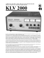
AMPLIFICATORE LINEARE DA STAZIONE BASE
BASE STATION LINEAR AMPLIFIER
KLV 2000
Lamplificatore lineare KLV 2000 è un amplificatore lineare ad alte prestazioni costruito per luso con tutti i ricetrasmettitori
HF in tutti i modi di trasmissione. Questo amplificatore usa due triodi 572B configurati in classe AB
2
con griglie a massa.
Opera in tutte le bande da 160 (1,8 MHz) a 10 (29,5 MHz) metri.
Una ventola interna a velocità variabile provvede al raffreddamento delle valvole, un circuito elettronico ne controlla il
funzionamento. Un circuito di Bias elettronico provvede al disinserimento delle valvole in fase di ricezione eliminando ogni
disturbo e la non necessaria dissipazione delle valvole. Un circuito di protezione previene il superamento della corrente
massima di griglia evitando il sovraccarico delle valvole in caso di errato accordo o sovrapilotaggio. Gli ampi indicatori vi
tengono sempre informati sui parametri vitali dellamplificatore, Potenza duscita, R.O.S., Corrente di griglia o Corrente
anodica, sono visualizzate per avere sotto controllo ogni momento lo stato di funzionamento dellamplificatore.
Vi raccomandiamo la lettura del presente manuale in tutte le sue parti prima della messa in funzione dellamplificatore.
Conoscere il funzionamento di tutte le sezioni dellamplificatore vi permetterà un uso più performante ed eviterà errori di
taratura o di posizionamento dei controlli che, oltre a causare una perdita di potenza duscita, potrebbe causare danni ai
componenti anche in maniera irreversibile. Un uso attento e corretto vi farà apprezzare le performance del KLV 2000 per
molti anni senza nessun intervento tecnico.
KLV 2000 is a high performance linear amplifier designed and made to be used with any HF transceivers in any transmission
mode. This amplifier is equipped with two 572B triode, in AB
2
classification with grounded grid.
It is operated in all the bands 160 m. to 10 m.
A variable speed inner fan provides the tubes cooling, an electrical circuit controls its operation. A bias electronic circuit
provides the tubes disconnection when receiving so that avoiding any disturb and unnecessary tube dissipation.
A protection circuit prevents the max grid current to be exceeded to avoid tubes overload in case either of wrong adjustment
or over input. The large indicator devices keep you advised on the basic parameters of the amplifier, output power, SWR,
grid current, anodic current or anodic tension are indicated to control continuously the amplifier operation. The reading of
the manual is recommended in all its parts before amplifier operation, the under standing of the detailed operation of the
amplifier will enable you to get the best performance and to avoid mistakes in adjustment or in controls positioning that
cause a loss of output power and possible damages on the components, even irreversibly. A careful and proper usage will
give you the chance to appreciate KLV 2000 performance for a lot of years with no need of technical service.

Indice - Index
1 Introduzione - Introduction
2 Indice - Index
3 Specifiche, Precauzioni, Garanzia - Specifications, Cautions, Warranty
4 Descrizione parte Anteriore - Front description
5 Descrizione parte Posteriore - Rear description
6 Tabella 1 - Table 1
Fig. 3
ITALIANO
7 Installazione
- Rimozione dallimballo ed ispezione
- Procedure dinstallazione
- Connessione alla rete
- Antenna
- Massa
8 Fig. 4 Connessioni al KLV 2000
Fig. 5 Tensioni di rete
9 Funzionamento
10 Fig. 6
ENGLISH
11 Installation
- Removal from package and inspection
- Installation
- Network connection
- Antenna
- Earth
12 Pic. 7 Connections to KLV 2000
Pic. 8 Connection to supply net
13 Operation
14 Pic. 9
- 2 -

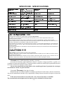
SPECIFICHE - SPECIFICATIONS
Ω
Ω
ATTENZIONE !!!!!
Allinterno del contenitore di questo lineare è presente alta tensione.
Il contatto con i circuiti ad alta tensione da parte delloperatore provoca danni alloperatore stesso e può
anche provocarne la morte.
Ogni operazione allinterno del lineare va effettuata da un tecnico specializzato in questo specifico settore
Prima dellapertura del KLV 2000 assicurarsi di aver sconnesso la spina di rete dalla presa e aver atteso almeno 5
minuti per permettere ai condensatori di alta tensione di scaricarsi.
Due interruttori di sicurezza sono posti allinterno del KLV 2000, uno disconnette lalimentazione di rete allapertura
della parte superiore del box, laltro cortocircuita lalta tensione alla rimozione della protezione dei circuiti RF in
lamiera traforata.
Laccensione del lineare con la protezione a lamiera traforata rimossa può provocare danni permanenti alloperatore
ed al KLV 2000.
CAUTION !!!!!
High voltages are present within the cabinet of this apparatus.
Harmful or fatal electric shock will result if high voltage circuits are touched by the user. Refer for all service work to
an experienced technician.
Safety interlock switches are included in the KLV 2000 to disconnect power if the top cover is removed. Do not
attempt to defeat these switches, and always disconnect the AC line before opening the cabinet
- 3 -
Garanzia mesi 24 dalla data dello scontrino o ricevuta.
Si ricorda che l'utilizzo degli amplificatori lineari è regolato da leggi specifiche e quindi se ne
consiglia la visione prima dell'utilizzo e comunque la ditta costruttrice declina ogni responsabilità derivata
da un non corretto uso rispetto le norme vigenti.
La non osservanza delle istruzioni sopra scritte annulla ogni forma di garanzia che comunque
non include le valvole e le parti estetiche.
24 monthes
Warranty, from date of receipt.
Remind that the use of linear amplifiers is ruled by special laws in each country, that are to be known.
Any way the manufacturer decline every responsibility coming from uncorrected use respect to the actual
rules.
If the above instructions are not observed, every form of warranty is cancelled.
The external and estetical parts and the tubes are never included in the warranty.

- 4 -
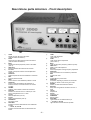
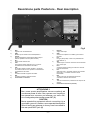
Descrizione parte Anteriore - Front description
1) LOAD
Regola laccordo del carico del lineare.
(Fare riferimento alla tabella 1)
2) TUNE
Regola laccordo della sezione anodica del lineare
(Fare riferimento alla tabella 1)
3) Band
Seleziona la banda (frequenza) di lavoro del lineare
(vedi 15)
4) SWR Sens.
Regola la taratura del fondoscala del rosmetro
5) Pre Tune
Regola la frequenza di lavoro del Preamplificatore
dantenna
6) Multimeter
Seleziona quale misura deve visualizzare il multimetro
7) Watt
Indica la potenza duscita
8) SWR
Indica il livello di onde stazionarie presenti in uscita
9) Multimeter
Indica, in base alla posizione del selettore 6, la
tensione anodica, la corrente anodica o la corrente
di griglia
10) DIR/REF
Selettore misura diretta o riflessa del rosmetro 8
11) Delay/ON
Inserisce un ritardo al ritorno in ricezione per luso
senza il collegamento al PTT in SSB
12) Lin/ON
abilita lamplificatore (vedi 16)
13) Pre/ON
Abilita il preamlificatore (vedi 16)
14) POWER/ON
Interruttore di rete
15) Meter/MHz
Indicatore luminoso della banda di lavoro selezinata
tramite 3
16) A, Lin ON, TX, Pre ON
Indicatori luminosi dello stato di funzionamento del
lineare
1
2
3
4
5
6
7
8
9
10
1
1
12
13
14
15
16
1) LOAD
Linear load adjustment
(refer to table 1)
2) TUNE
Linear anodic section adjustment
(refer to table 1)
3) Band
Linear working band (frequency) selection (see15)
4) SWR Sens.
SWR end of scale adjustment
5) Pre Tune
Antenna preamplifier working frequency adjustment
6) Multimeter
Select the measure to be indicated by multimeter
7) Watt
Output power level
8) SWR
Output stationary wawes level
9) Multimeter
It indicates, dependig on position of 6, the anodic
tension, the anodic current or the grid current
10) DIR/REF
Selector of SWR direct/reflected measure
11) Delay/ON
Delay when using without connection with PTT in
SSB
12) Lin/ON
Amplifier ON
13) Pre/ON
Preamplier ON
14) POWER/ON
Network switch
15) Meter/MHz
Light indicator of the selected band by 3
16) A, Lin ON, TX, Pre ON
Light indicators of linear status of operation
Fig 1

- 5 -
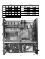
1) Rete
Ingresso cavo di alimentazione
2) GND
Morsetto per la messa a terra dellamplificatore
3) Ventola
Griglia di aspirazione ventola (deve essere sempre
libera da qualsiasi cosa che possa ostruirla)
4) ALC
Presa duscita controllo ALC
5) PTT+
Una tensione positiva superiore a 6 V provoca la
commutazione in trasmissione del lineare
6) PTT-
La messa a massa di questo ingresso o comunque
una tensione inferiore a 4V provoca la commutazione
in trasmissione del lineare
7) RTX
Connettore SO239 di ingresso del lineare
8) ANT
Connettore SO239 di uscita del lineare
9) Connessioni e avvertenze
Descrizione parte Posteriore - Rear description
1) Network
Supply cable input
2) GND
Connect the amplifier to the station ground bus at
this point
3) Fan
Fan grid (always keep it free of any materials that
could obstruct it)
4) ALC
This RCA jack is used for connection to the trasceiver
ALC control input
5) PTT+
A positive tension exceding 6V cause the commute
to linear transmission
6) PTT-
When this input in grounded, however with a tension
lower than 4 V, it causes commute to linear
transmission
7) RTX
The RF input from the transceiver should be
connected to this SO 239 connector
8) ANT
This SO 239 connector provides the RF output to the
antenna
9) Connections and notices (advices)
ATTENZIONE !!
Non usare questo amplificatore senza connetterlo ad
una buona presa di terra. Non operare con lamplifica-
tore senza aver connesso unantenna o un carico fitti-
zio di adeguata potenza alla presa ANT (8)
CAUTION
Never operate this equipment without connecting it to a
good earth ground. Likewise, never operate the amplifier
wthout having an antenna or dummy load connected to
the rear panel ANT jack (8)
Fig 2
1
2
3
4
5
6
7
8
9

- 6 -
Tabella 1 Table 1
BAND
Freq
MHz
TUNE
LOAD
OurYour
Our
Your
10
12
15
17
20
30
40
80
160
28.0
Center
Center
Center
Center
Center
Center
Center
Center
Center
29.7
24.5
25.0
21.0
21.5
18.0
18.5
14.0
14.5
10.0
10.5
7.0
7.5
3.5
4.0
1.8
2.0
BAND
Freq
MHz
TUNE
LOAD
OurYourOur Your
Fig 3

- 7 -
I
Rimozione dallimballo e Ispezione
Rimuovere, con molta attenzione, il KLV 2000 dal pro-
prio imballo, controllare che il lineare non abbia nes-
sun segno visibile di danni. Muovere delicatamente ogni
controllo e interruttore per controllare che abbiano un
normale funzionamento. Se è rilevato qualche danno,
fate una relazione dettagliata ed inviatela o consegna-
tela immediatamente al vostro fornitore. Conservare
limballo completo da riutilizzarsi in caso di necessità.
E obbligatorio luso dellimballo originale in caso di rien-
tro presso un centro di riparazione.
Procedura dinstallazione
Lamplificatore deve essere posto in modo che vi sia
un ampio spazio attorno, in modo che il flusso daria
sia libero di circolare permettendo una corretta venti-
lazione di tutte le parti. Non porre libri, carta, o altri
oggetti sulla parte superiore del KLV 2000, non porre
nulla che possa ostruire la griglia posteriore. Una limi-
tazione del flusso di ventilazione può danneggiare
in maniera irreversibile il lineare.
Per il dettaglio delle connessioni di uninstallazione ti-
pica del KLV 2000, fare riferimento alla fig.4.
Lingresso ALC del ricetrasmettitore va connesso al-
luscita ALC (4 fig. 2) del KLV 2000. Luscita PTT del
ricetrasmettitore allingresso PTT (6 fig. 2, più raramen-
te 5 fig.2) del lineare. In caso di mancato uso di questa
connessione un circuito interno al KLV 2000 fornisce il
segnale di commutazione, per un miglior controllo del-
la commutazione, si consiglia in ogni caso luso dellin-
gresso PTT.
Entrambi i connettori sopra menzionati sono di tipo
RCA.
Usare un corto spezzone di cavo coassiale tipo RG-
58A/U o RG-8A/U o equivalenti per linterconnessione
delluscita del ricetrasmettitore al connettore RTX (7
fig.2) del KLV 2000. Per la connessione delluscita ANT
(8 fig.2) del KLV 2000 allantenna non usare cavo sot-
tile tipo RG-58 ma solo un cavo che sopporti ampia-
mente la potenza duscita, cavi adeguati sono RG8A/
U, RG-213/U o equivalenti.
Il ricetrasmettitore usato per pilotare il KLV 2000 deve
essere in grado di fornire 100 W PEP per avere la
massima potenza in uscita del lineare.
Connessione alla Rete
Lalimentatore per il funzionamento del KLV 2000 è in-
cluso al suo interno, è in grado di operare alle tensioni
di rete di 100/110/120/200/220/240 Vac 50/60 Hz. Pri-
ma di connettere la spina di rete assicurarsi della cor-
retta tensione di lavoro scritta sulladesivo posteriore
(9 fig.2). Fare riferimento alla figura 5 o allo schema
elettrico per la modifica della tensione di lavoro.
Il fusibile di rete dipende dalla tensione dalimentazio-
ne ed è importante che sia correttamente dimensionato,
per tensioni di 100/110/120 Vac deve essere da 20 A
Fast, per tensioni di 200/220/240 Vac deve essere da
10 A Fast.
Un circuito interno di ritardo limita il picco di corrente
allaccensione.
Il KLV 2000 deve essere connesso ad una presa di
rete indipendente senza interporre adattatori o altri
accessori che potrebbero provocare surriscaldamenti
delle connessioni danneggiandole.
I conduttori del circuito di rete non devono essere infe-
riori a 2,5 mm² per tensioni di 200/220/240 Vac o #10
AVG per tensioni di 100/110/120 Vac.
Se durante luso del KLV 2000 si nota un notevole ab-
bassamento dellintensità luminosa di lampadine po-
ste nello stesso locale dellamplificatore, i conduttori di
rete probabilmente sono di sezione insufficiente per
luso in sicurezza dello stesso.
ANTENNA
Il KLV 2000 è costruito per luso con antenne che pre-
sentano un carico resistivo di 50 75 Ω sulla frequen-
za di lavoro, in caso di uso di unantenna che non ri-
sponde a questi requisiti si consiglia luso di un adatta-
tore dimpedenza o di un accordatore, in grado di por-
tare limpedenza vista dallamplificatore alla sua uscita
nei limiti richiesti. Si ricorda che accessori a valle del-
lamplificatore devono ampiamente sopportare la po-
tenza duscita dello stesso, accessori inadeguati pos-
sono provocare danni irreversibili allamplificatore.
MASSA
Questo amplificatore deve essere connesso allimpian-
to di terra della stazione radio, usando una trecciola di
adeguata sezione, non più lunga di 3 m. Il cavo di terra
deve essere connesso allapposito morsetto posterio-
re (2 fig. 2). Verificare che limpianto di terra della sta-
zione sia di ottima qualità, questo eliminerà molti di-
sturbi in ricezione, preverrà accumulo di cariche
statiche ed eviterà che ci siano punti a tensione RF
elevata in trasmissione sulle parti metalliche che è
possibile toccare.
ATTENZIONE !!!!
Luso dellamplificatore con una tensio-
ne di rete impropria provoca danni per-
manenti, la garanzia non copre i danni
provocati da unalimentazione impro-
pria o con un fusibile non corretto.

- 8 -
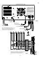
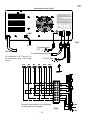
Fig 4
I
Alla presa di rete
Allimpianto
di terra
Al PTT del
ricetrasmettitore
Al ricetrasmettitore
Alla presa ALC
Allantenna
GND
Per la connessione del PTT e
dellALC al Ricetrasmettitore fare ri-
ferimento al suo manuale duso
Fig 5
Possibili connessioni al primario del
trasformatore di alimentazione
Connessioni al KLV 2000

- 9 -
FUNZIONAMENTO
Prima di iniziare qualsiasi operazione verificare che
la tensione presente alla presa dalimentazione di
rete corrisponda alla tensione impostata nellali-
mentatore del KLV 2000, vedi fig. 5 (limpostazione
di fabbrica è scritta sulladesivo posteriore 9 fig.
2). Verificare che unantenna adeguata sia connes-
sa al connettore ANT del lineare (8 fig.2).
Il ricetrasmettitore, usato per pilotare il KLV 2000, deve
essere accordato prima che possa operare in accop-
piamento al lineare. Se laccordo dellRTX viene ese-
guito a lineare acceso, linterruttore 12 deve essere
posto su OFF (indicatore Lin ON spento 16 fig.1).
Posizionare i comandi del KLV 2000 nel seguente modo
(fare riferimento alla fig.1):
Power/ON ......................... OFF
Lin/ON .............................. OFF
Pre/ON ............................. OFF
Multimeter ......................... Va
Band ................................. Banda desiderata
TUNE ............................... Vedi Tabella 1 pag. 6
LOAD ............................... Vedi Tabella 1 pag. 6
SWR Sens................ 0 (completamente antiorario).
Accendere Lamplificatore tramite il comando Power/
ON (posizione ON), un ritardo di due o tre secondi pri-
ma della completa illuminazione degli strumenti è nor-
male, assicurarsi della perfetta sintonia del
ricetrasmettitore (apparati a valvole). Controllare sullo
strumento Amplifiers Parameters il livello di tensio-
ne anodica, lago deve essere circa a 2,5 della scala
inferiore (Va). Unindicazione differente potrebbe indi-
care unerrata tensione dalimentazione, spegnere tut-
to e controllare limpostazione del cambia-tensione
fig.5.
Assicurarsi che il selettore di banda di frequenza (3
fig.1) sia sulla banda appropriata.
Commutare Multimeter (6 fig.1) su Ia, porre il con-
trollo di potenza duscita del trasmettitore al minimo,
commutare Lin/ON (12 fig. 1) su ON (accensione di
LinON 16 fig. 1).
Premere il PTT del microfono per portare in trasmis-
sione il trasmettitore, il KLV 2000 commuta in trasmis-
sione e visualizza la condizione accendendo la spia
TX (16 fig. 1). Aumentare il controllo di potenza fino a
leggere 200 mA (.2 A) sullo strumento 9 fig. 1, regolare
il controllo TUNE (2 fig.1) fino ad ottenere la massima
potenza duscita letta sul wattmetro (7 fig. 1) che deve
corrispondere al dip (minimo) della corrente anodica
assorbita (visualizzata su 9 fig. 1). Rilasciare il PTT
per tornare in ricezione.
Attendere qualche attimo, premere di nuovo il PTT ed
aumentare la potenza fino a leggere sul multimetro (9
fig. 1) 400 mA (.4 A) regolare alternativamente i co-
mandi TUNE e LOAD (2 e 1 fig. 1) per ottenere la
massima potenza duscita letta sul wattmetro, rilascia-
re il PTT.
ATTENZIONE !!!! IN FASE DI TARATURA NON RI-
MANERE IN TRASMISSIONE (KEY-DOWN) PER PIU
DI 10 SECONDI SENZA INTERCALARE UNA FASE
DI RICEZIONE SUFFICIENTEMENTE LUNGA DA
PERMETTERE IL RAFFREDDAMENTO DELLE VAL-
VOLE FINALI, LECCESSIVO
SURRISCALDAMENTO PROVOCA IL PREMATURO
ESAURIMANTO DEI TUBI.
Portare la potenza delleccitatore (RTX) a circa 100 W
PEP e controllare la taratura del lineare. In queste con-
dizioni il KLV 2000 fornisce la sua massima potenza
duscita.
Durante la fase di taratura ed in particolar modo du-
rante luso, la spia di pericolo A (16 fig. 1) deve rima-
nere spenta. Questa spia indica il superamento di 500
mA dassorbimento di corrente anodica o lintervento
della protezione per eccessiva corrente di griglia, con-
dizioni di pericolo per la vita delle valvole. Se durante
laccordo interviene la protezione di griglia, diminuire il
pilotaggio ed aumentarlo solo ad accordo eseguito.
La posizione dei comandi TUNE e LOAD per la massi-
ma potenza duscita su un carico di 50
Ω è segnalata
nella tabella N°1 a pag. 6 .
Si può ora eseguire la taratura del Rosmetro incorpo-
rato. Commutare il pulsante 10 (DIR/REF) in DIR (la
variazione dellindicazione del wattmetro è normale),
premere il PTT ed aumentare il controllo SWR Sens.
(4 fig. 1) fino a portare lago dello strumento SWR (8
fig. 1) al fondo-scala posizione ∞, portare il comando
10 in posizione REF, lindicazione dello strumento SWR
(8) visualizza ora il ROS alluscita del KLV 2000.
E importante che, durante luso dellamplificatore, il
livello delle onde stazionarie (ROS) rimanga sempre
ad un livello accettabile, mai superiore a 3 e possibil-
mente inferiore a 1,5. Un minor ROS aumenta il tra-
sferimento di potenza e quindi la potenza irradiata dal-
lantenna, un ROS maggiore di 3 può pregiudicare la
vita delle valvole.
Durante luso in SSB, regolare la potenza di pilotaggio
per una corrente anodica assorbita di 0.2 0.3 A
parlando normalmente al microfono, questo perché lo
strumento del KLV 2000 visualizza lassorbimento
medio del circuito di placca ed i picchi sono il doppio di
questo.
Per luso in AM FM - FSK regolare la potenza del
trasmettitore per una corrente anodica di 0.2 0.3 A
con la portante non modulata e limitare nel tempo la
trasmissione senza pause (ricezione) sufficienti a far
raffreddare le valvole.
Il multimetro (9 fig. 1) visualizza anche la corrente di
griglia, essa dipende dalla taratura del circuito duscita
e dalla potenza dingresso. La corrente di griglia non
deve mai superare i 90 mA, un circuito di protezione
I

- 10 -
impedisce luso del lineare se viene superato questo
valore e visualizza la condizione accendendo in ma-
niera permanente la spia di pericolo A (16 fig. 1) ed
impedisce il funzionamento del lineare. Per il ripristino
del funzionamento del KLV 2000 portare momentane-
amente su OFF il comando Lin/ON (12 fig. 1).
Altro motivo dintervento della protezione, quindi ac-
censione della relativa spia e il mancato funzionamen-
to del KLV 2000, è il non perfetto funzionamento della
ventola di raffreddamento. Un controllo elettronico sul
motore della ventola segnala uneventuale anomalia
al circuito di protezione, in questa condizione il ripristi-
no del funzionamento del KLV 2000 tramite il coman-
do Lin/ON non funziona e lintervento di un tecnico è
necessario. Lintervento della protezione della ventola
avviene anche allaccensione del lineare se il commu-
tatore Lin/ON (12 fig. 1) è in posizione ON, questo per-
ché la velocità della ventola richiede qualche secondo
per raggiungere il livello prefissato. In questo caso lin-
tervento sul comando Lin/ON ripristina il funzionamento
del KLV 2000.
Il comando Delay/ON (11 fig. 1) inserisce nella posi-
zione ON un ritardo di circa 2 secondi al rilascio del
relè di commutazione necessario in SSB e CW nel caso
che non sia usata una delle prese posteriori PTT (5 o
6 fig. 2) e quindi il KLV 2000 commuta tramite il circuito
VOX interno. Il ritardo serve ad evitare che il relè dan-
tenna torni a riposo quando il segnale dingresso scen-
de a zero durante le brevi pause di trasmissione.
Linserimento del preamplificatore dantenna avviene
tramite il comando Pre/ON (13 fig. 1). Per luso è ne-
cessario sintonizzare il circuito del preamplificatore alla
frequenza dutilizzo tramite il comando Pre Tune (5 fig.
1), a preamplificatore spento sintonizzare nel ricevito-
re un segnale vicino alla frequenza di lavoro, accende-
re il preamplificatore e ruotare il comando Pre Tune
lentamente in una direzione o nellaltra fino a trovare la
posizione di massima deflessione dello Smeter del ri-
cevitore.
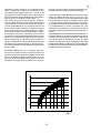
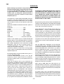
Il preamplificatore funziona sostanzialmente da circui-
to passa-banda con una larghezza limitata. Attraverso
il controllo di sintonia (5 fig.1) amplifica il segnale da
circa 30 a 9,5 MHz e lo attenua da circa 9,5 a 6,5 MHz
secondo il diagramma in fig. 6 consentendo, grazie alla
limitata banda passante, di diminuire lintermodulazione
di segnali forti su frequenze adiacenti ed amplificare i
segnali bassi nelle bande alte.
dB
Band
0
-10
+10
+15
+20
+25
-5
+5
10m12m15m17m20m30m40m
Fig 6
Caratteristica di funzionamento del Preamplificatore dantenna
I

G
Removal from package and inspection
Carefully remove the KL
V 2000 from its package and
check for damages on the linear.
Carefully move any control and switch to check they
are regularly working. In case any damages is found,
prepare a detailed report to be immediately sent to your
supplier. Keep the complete package to be re-used if
required. The original package must be used if the piece
has to be returned to a service centre.
Installation
The amplifier needs a lot of room all around so that air
can freely circulate, enabling a proper ventilation to all
components.Do not put, books, paper or any other
object on the top of KLV 2000, do not create any
obstruction to the back grill.
A limited and difficult ventilation can severely
damage the linear.
For details about the connections please refer to pic.
7.
The ALC input of the transceiver has to be connected
to the ALC output (4 pic. 2) of KLV 2000. The PTT
output of the transceiver has to be connected to the
PTT input (6 pic.2, seldom 5 pic. 2) of the linear. When
this connection is not used an internal circuit provides
the commuting signal. For a better control on
commuting it is any way advisable the usage of PTT
input.
Both the above mentioned connectors are of RCA type.
Use a short coaxial cable RG 58 A/U or RG 8 A/U type
for the interconnection of the output of the transceiver
to the RTX connector (7 pic. 2) of the KLV 2000. For
the ANT output (8 pic. 2) connection to the antenna
never use a thin cable such as RG 58, use only a cable
able to bear the output power, adequate cable are RG
8 A/U, RG 213 /U or equivalent.
The transceiver used to drive the KLV 2000 has to be
able to provide 100 W PEP to get the max output power
of the linear.
Network connection
The supply for the KLV 2000 already included with the
set, is able to work on network tension 100/110/120/
200/220/240 Vac 50/60 Hz. Before connecting the
network plug be assured that the tension is the correct
one as written on the sticker on the back (9 pic. 2).
To modify the working tension refer to Picture 8 or to
electric scheme.
The network fuse depends on the supply tension.
Its size is very important, for 100/110/120 Vac it as to
be of 20 A fast, for 200/220/240 Vac it has to be of 10 A
fast.
An inner delay circuit gives a limit to the pick of current
when switching on.
The KLV 2000 has to be connected to a plug of an
independent network, without any adaptor or different
devices that could cause heating of the connections,
so that they could be damaged. Conductor of the
network circuit does not have to be lower than 2,5 mm²
for 200/220/240 Vac tension or 10 AWG for 100/110/
120 Vac tension. If during the use of KLV 2000 a
considerable lowering of the lights placed in the same
room as the amplifier is noted, the network connector
has not a sufficient section to use safely the same.
Antenna
The KLV 2000 is designed to be used with antennas
featuring a load of 50 75
Ω on the working frequency.
In case you are using an antenna with different features
the use of any impedance adaptor or of an impedance
matcher is advisable because they are able to bring
the impedance seen by the amplifier to its output within
the required limits. Remind that devices receiving from
the amplifier must bear its output power because when
they are not adequate irreparable damages can be
caused.
Earth
This amplifier has to be connected to the earth of the
radio station, using a cable with the proper section, not
longer that 3 m. The earth cable has to be connected
to the suitable back pin (2 pic. 2) verify that the earth of
the station is of the best quality, this will avoid problems
when receiving, will prevent the accumulation of static
charges and will avoid zones with high RF tension in
transmission on the metal parts that can be touched.
Attention !!!!
The use of the amplifier with a not
proper network tension creates
permanent damages The warranty
does not cover damages given by a
not proper supply or by a not proper
fuse.
- 11-

- 12 -
Fig 7
G
Network plug
Earth
To ricetranceiver
PTT
To ricetranceiver RF plug
To ALC plug
To antenna
GND
For connection of PTT and ALC to
the transceiver refer to its usage
section
Fig 8
Possible connections to the primary
of the trasformer of supply
Connections to KLV 2000

G
OPERATION
Before starting any operation verify the tension in
the network supply plug corresponds to the tension
as set up in the KLV2000 supply, see pic. 8, (the
original adjustment is described on the back
stickers 9 pic. 2). Verify that a proper antenna is
connected to the ant connector of the Linear
Amplifier (8 pic.2).
The transceiver, used to guide the KLV2000, has to be
set before it can work coupled with the linear. When
the RTX set is carried out with linear on, the 12 switch
has to be place on OFF ( Lin ON indicator, switch OFF
16 fig. 1).
Place the KLV2000 commands as<follows: (Refer to
picture 1):
Power/ON .................................... OFF
Lin/ON ......................................... OFF
Pre/ON ........................................ OFF
Multimeter .................................... Va
Band ............................................ Prefer Band
Tune ............................................ See...1 page 6
Load ............................................ See...1 page 6
SWR Sens .............................O Counter clock wise
Switch on the Amplifier by the command Power/ON
(Position ON), A 2-3 seconds delay before a complete
lightening of the instruments is normal, be assured to
get a proper adjustment of the transceiver (TUBE
DEVICES), check the level of anodic tension on
<Amplifier Parameters > the pointer should indicate
aprox 2,5 on the lower scale (Va).
A different indication could mean a wrong supply
tension, switch everything OFF and check the tension
adjuster setup Pic.8
Be assured that the frequency band selector (3 pic. 1)
is on the appropriate band.
Commute <MULTIMETER> (6 Pic.1) on Ia, put the
transceiver power output control on minimum,
commute Lin/ON (12 Pic.1) on ON (switch ON of Lin/
ON 16 pic.1).
Push the microphone PTT to the transmitter on
transmission, KLV2000 commutes in transmission and
show the condition by the TX light (16 pic.1). Increase
the transceiver power control till reading 200 Ma (.2
Amp) on device 9 pic.1, adjust tune control (2 pic.1)
until you get the max output power read on the
wattmeter (7 pic.1), it corresponds to the minimum
absorbed anodic current (shown on 9 pic.1). Release
PTT and enter reception again. Wait for few moments,
push again PTT increase the power until you read on
the multimeter (9 pic.1) 400mA (.4 Amp) and adjust
alternatively the commands TUNE and LOAD (2 and 1
pic.1) to get the max output power on wattmeter, release
PTT.
ATTENTION !!! WHEN ADJUSTING DONT STAY IN
TRANSMISSION (KEY DOWN) FOR OVER 10
SECONDS WITHOUT INTERRUPTING BY MEANS
OF A RECEPTION PHASE LONG ENOUGH TO
PERMIT THE COOLING OF THE END TUBES. THE
EXCESSIVE HEATING CAUSES THE PREMATURE
EXHAUSTION OF THE TUBES.
Bring excitatory power (RTX) to about 100 W PEP and
check the linear adjustment. In this status the KLV 2000
provides its max output power, that has to correspond
to the dip of the anodic current (Ia).
During adjustment, and especially during usage, the
danger indicator
A (16 pic. 1) has to be off, this light
indicates either the exceeding of 500 mA of anodic
current absorption or the protection for too high grill
current that can be dangerous for the tubes life. When
during tuning the grill protection is entered, decrease
input power and increase again only after adjustment.
The position of Tune and Load commands for the max
output power on a 50
Ω load is indicated in the Table 1,
page. 6.
Now the SWR-meter adjustment can be effected.
Commute button 10 fig. 1 (Dir/Ref) in Dir (the variation
of indication of wattmeter is normal), press PTT button
and increase SWR Sens. control (4 pic. 1) to put the
pointer of SWR devices (8 pic. 1) to the bottom of the
scale, position ∞, bring the command 10 on Ref, now
the indication of SWR devices (8) shows the SWR at
the KLV 2000 output.
During the use of the amplifier, the level of the stationary
waves (SWR) has to remain to an acceptable level,
never exceeding 3 and possibly lower than 1,5. A lower
SWR increase the power transfer therefore also the
antenna irradiated power, a SWR higher than 3 can be
dangerous for the life of the tubes.
When using in SSB, adjust the input power for an
absorbed anodic current of 0.2 0.3 A speaking at the
microphone, because the KLV 2000 devices indicates
the medium absorption of the Plate circuit, and the peak
are double of this.
For usage in AM FM FSK adjust the transceiver
power for an anodic current of 0.2 0.3 A, the carrier
not modulated and its usage without breaks (reception)
has to be limited to time sufficient to get the tubes
cooled down.
- 13 -

The multimeter (9 pic.1) indicates also the grid current,
it depends on the set-up of the output circuit and the
input power. The grid current does not have to exceed
90 mA. A protection circuits makes the linear usage
impossible when this value is exceeded and indicates
this condition switching ON the danger indicator
A (16
pic. 1) and preventing the linear operation, to restart
the KLV 2000 operation bring the command Lin/ON on
OFF (12 pic. 1). Additional reason for the protection to
be entered - therefore the lightening of the
corresponding light and the KLV 2000 stoppage is
the non proper operation of the cooling fan. An
electronic control on the fan motor shows an eventual
anomaly on the protection circuit in this condition the
restarting of KLV 2000 operation by means of the Lin/
ON command is not working, and a technician has to
be contacted. The protection is entered also when the
linear is switched ON, if the command Lin/ON is on
position ON (12 pic. 1), because the fan speed required
few seconds to reach the fixed level, in this case the
operation on command Lin/ON make the KLV 2000
restart.
The Delay/ON command (11 pic. 1) enters, in position
ON, a delay of about 2 seconds when releasing the
relay of commuting, necessary in SSB an CW in the
case when one of the back plug PTT (5 or 6 pic. 2) is
not used so that KLV 2000 commutes by the inner VOX
circuit. The delay is for avoiding the antenna relay to
standby when the input signal is zero during the short
transmission break.
The antenna preamplifier is inserted by means of the
command Pre/ON (13 pic. 1). To use, adjust the pre-
tune command (5 pic. 1) to the used frequency. When
the amplifier is off, syntonize a signal close to the
working frequency in the receiver, switch the
preamplifier ON and slowly turn the command Pre Tune
in a direction or the other to find the max deflection
position of the s-meter of the receiver.
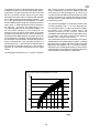
The preamplifier works as a Pass-band circuit, with a
limited width. Across tuning frequency (16 pic. 1) amplify
the signal 30 to 9,5 MHz and lower it down 9,5 to 6,5
MHz as per the diagram in pic. 9, this way it enables,
also thank to the limited passing-band, to decrease the
intermodulation of loud signals on adjacent frequencies
and to amplify the low signals in high bands.
dB
Band
0
-10
+10
+15
+20
+25
-5
+5
10m12m15m17m20m30m40m
Fig 9
Gain versus frequency preamplifier curve chart
G
- 14 -
-
 1
1
-
 2
2
-
 3
3
-
 4
4
-
 5
5
-
 6
6
-
 7
7
-
 8
8
-
 9
9
-
 10
10
-
 11
11
-
 12
12
-
 13
13
-
 14
14


in altre lingue
- English: RM KLV 2000 User manual
Documenti correlati
Altri documenti
-
Albrecht SWR-20 Manuale utente
-
 RM Italy KLV 1000 Manuale utente
-
RM Italy KL 505V Istruzioni per l'uso
-
Sirio Antenne CARBONIUM 27SUPER CARBONIUM 27 Manuale utente
-
 Autek Research WM-1 SWR Instructions Manual
-
RM Italy KL 35 Manuale utente
-
 Metropwr FX-Master Microphone EQ Manuale utente
-
Sony KLV-L32M1 Istruzioni per l'uso
-
-
Sony KLV-40U2520 Manuale del proprietario


