Falmec FNLUM36I5SS Manuale utente
- Categoria
- Cappe da cucina
- Tipo
- Manuale utente
Questo manuale è adatto anche per

EN INSTRUCTIONS BOOKLET
FR MODE D'EMPLOI
ES MANUAL DE INSTRUCCIONES
IT LIBRETTO ISTRUZIONI
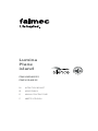
Lumina
Plane
island
FNLUM36I5SS
FNPLS36I5SS

2
2 1/8” - 55 mm
23 5/8” - 600 mm
max 22 5/8” - 575 mm
35 3/8” - 900 mm
23” - 585 mm
12 1/4” - 310 mm
15 1/4” - 387 mm
5 7/8” - 150 mm
25 3/4” - 655 mm
max 48 3/8” - 1230 mm
4 4/8” - 115 mm
99 lb
45 kg
Lumina 36" Cod.: FNLUM36I5SS 120VAC 60Hz 280W

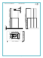
2 6/8” - 70 mm
15 1/4” - 387mm
23 5/8” - 600 mm
12 1/4”
310mm
max 49” - 1244 mm
35 3/8” - 900 mm
21 5/8” - 550 mm
11 7/8” - 301 mm
4 1/2” - 115 mm
92 lb
42 kg
Plane 36" Cod.: FNPLS36I5SS 120VAC 60Hz 280W

4
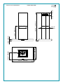
180 mm
7 1/8”
CEILING
FALSE
CEILING
20 5/8” - 523 mm
min. 11” - 280 mm
max. 32 3/4” - 832 mm
Ø150 mm
Ø 5 7/8”
Ø226 mm
Ø 8 7/8”
Ø 9 7/8”
Ø250
mm
13 7/8” - 353 mm
9 5/8” - 245 mm
15” - 382 mm
11 3/4” - 300 mm
Ø 1/4” - 6 mm
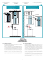
EN - Side outlet which can only be used with false ceiling.
FR - Sortie latérale utilisable uniquement avec faux-plafond.
ES - Salida lateral utilizable solo con falso techo.
IT - Uscita laterale utilizzabile solo con controsotto.
ø5/16"
8 mm
ø1/4"
6 mm
EN- tool required
FR- outil requis
ES- herramienta
requerida
IT - Attrezzi necessari
EN- cable length 5,0ft (1,5m)
FR- longueur de câble 5,0ft (1,5m)
ES- longueur de câble 5,0ft (1,5m)
IT- lunghezza cavo 5,0ft (1,5m)

5
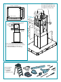
1
2
3
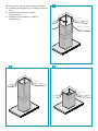
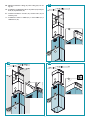
EN - False ceiling (1), ceiling (2) and low ceiling (3) installation.
FR - Installation sur faux-plafond (1), sur plafond (2) et plafond
bas (3).
ES - Instalación en falso techo (1), en techo (2)
y en techo bajo (3).
IT - Installazione su controsotto (1), a sotto (2)
e sotto basso (3).
CEILING
FALSE CEILING
CEILING
CEILING

6
H1
Z
CEILING
Ø 5 7/8” - 150mm
NRS
H = Z + 4 3/4” - 120 mm
NRS
A
NRS
Z
F
FALSE CEILING
H1
CEILING
H = Z - 4 3/4” - 120 mm
NRS
7 1/8”
180 mm
A
A B
EN INSTALLATION WITH FALSE CEILING
FR INSTALLATION AVEC FAUXPLAFOND
ES INSTALACIÓN CON CIELO RASO
IT INSTALLAZIONE CON CONTROSOFFITTO
EN INSTALLATION ON CEILING
FR INSTALLATION AU PLAFOND
ES INSTALACIÓN EN TECHO
IT INSTALLAZIONE A SOFFITTO
EN - Measurements for
installation.
FR - Mesures pour
l'installation.
ES - Medidas para la
instalacion.
IT - Misure per l’installazione.
EN - Installation measurements
Recommended mounting height from cooking surface to hood bottom
is indicated by "A" in the drawing below.
It is recommended to install the hood in this range to optimize perfor-
mance. It is recommended to not exceed 35” (890mm) for dimension “A”
as hoods mounted above this may be difficult to reach for average height
users and performance and efficiency will degrade.
Hoods mounted below the lower measurement in the “A” recommenda-
tion could result in damage due to heat and present a fire hazard and
would avoid any warranty claims attributable to the lower mounting po-
sition.
If available, also refer to the cooking appliance manufacturer’s height
clearance recommendations and adhere to national and local building
and fire codes which supersede any recommendations stipulated herein.
FR - Mesures pour installation
La hauteur de montage recommandée entre la surface de cuisson et la
partie inférieure de la hotte est indiquée par le « A » dans le dessin ci-des-
sous.
Il est recommandé d’installer la hotte dans cette plage pour optimiser
sa performance. Il est recommandé de ne pas dépasser les 890 mm (35
po) pour la dimension « A », car les hottes montées à une distance au-
dessus peuvent être difficiles à atteindre pour les utilisateurs de hauteur
moyenne, et cela diminuera leur performance et efficacité.
Les hottes montées en-dessous de la mesure inférieure de la recomman-
dation « A » pourraient s’abîmer par la chaleur et présenter un risque
d’incendie, ce qui annulerait toute réclamation de garantie attribuable à
la position de montage inférieure.
Le cas échéant, reportez-vous également aux recommandations du fabri-
cant de l’appareil de cuisson en ce qui a trait au dégagement en hauteur
et respectez les codes du bâtiment et de prévention des incendies natio-
naux et locaux qui remplacent toutes les recommandations stipulées
dans le présent document.
A = 24" - 35"
610 mm - 890 mm
(RECOMMENDED FOR
OPTIMAL PERFORMANCE)

7
1
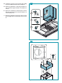
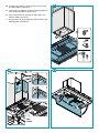
EN - Preliminary operations:
remove the panel and the
metal lters (1).
FR - Opérations préliminaires:
enlever panneau et ltres
métalliques (1).
ES - Operaciones preliminares:
quitar el panel y los ltros
metálicos (1).
IT - Operazioni preliminari:
togliere pannello e ltri
metallici (1).
2
6
5
1
2
3
4
ES - Medidas instalación
La altura de montaje recomendada desde la superficie de cocción hasta
el fondo de la campana se indica con una "A" en el dibujo siguiente.
Se recomienda instalar la campana en este rango para optimizar el rendi-
miento. Se recomienda no exceder 35" (890mm) para la dimensión "A" ya
que las campanas montadas por encima de ésta pueden ser difíciles de
alcanzar para los usuarios de altura media y el rendimiento y la eficiencia
se degradarán.
Las campanas montadas por debajo de la medida inferior de la recomen-
dación "A" podrían resultar dañadas por el calor y presentar un riesgo
de incendio, y evitarían cualquier reclamación de garantía atribuible a la
posición de montaje inferior.
Si está disponible, consulte también las recomendaciones de altura del
fabricante del equipo de cocina y respete los códigos de construcción
y contra incendios, nacionales y locales, que sustituyen cualquier reco-
mendación estipulada en el presente documento.
IT - Misure per l'installazione
L’altezza di montaggio consigliata tra il piano cottura e la parte inferiore
della cappa è indicata dalla lettera “A” nella figura sottostante.
Per ottenere prestazioni ottimali, si raccomanda di installare la cappa en-
tro i limiti, massimo e minimo, mostrati nella figura. È consigliabile che le
dimensioni di “A” non superino i 35” (890mm) in quanto le cappe monta-
te più in alto potrebbero presentare un livello ridotto di rendimento ed
efficienza, oltre a risultare difficili da raggiungere da parte degli utenti di
altezza media.
Al contrario, le cappe montate al di sotto dell’altezza minima consigliata
in “A” potrebbero danneggiarsi per il calore proveniente dal piano cottura
e presentare un rischio di incendio.
Si ricorda che la garanzia non risponde
di eventuali danni derivanti da un montaggio in posizione troppo bassa.
Se disponibile, fare riferimento anche all’altezza libera raccomandata dal
produttore del piano cottura. In ogni caso, è sempre necessario rispettare
le norme edilizie e antincendio in vigore, a livello sia nazionale sia locale,
le quali prevalgono su qualsiasi raccomandazione contenuta nel presente.

8
2
3
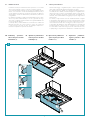
EN - Preliminary operations: disconnect the connector (2), disconnect the Lumina connector (3).
FR - Opérations préliminaires:
débrancher connecteur (2), débrancher connecteur Lumina (3).
ES - Operaciones preliminares:
desconectar el conector (2), desconectar el conector Lumina (3).
IT - Operazioni preliminari: scollegare connettore (2), scollegare connettore Lumina (3).
2
1
2
Lumina NRS
x3
1

9
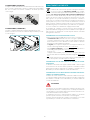
4
5
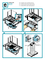
EN - Preliminary operations: motor chamber disassembly
(4), motor chamber bottom trestle assembly (5).
FR - Opérations préliminaires: démontage chambre mo-
teur (4), xation support inférieur sur chambre mo-
teur (5).
ES - Operaciones preliminares: desmontaje de la cámara
del motor (4), montaje de la estructura inferior a la
cámara del motor (5).
IT - Operazioni preliminari: smontaggio camera motore
(4), montaggio traliccio inferiore alla camera motore
(5).
4
1
2
3

10
6
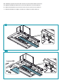
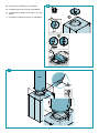
EN - Check valve (6) and NRS pipe (7) installation.
FR - Installation clapet anti-retour (6) et tube NRS (7).
ES - Instalación de la válvula de no retorno (6) y tubo
NRS (7).
IT -
Installazione valvola di non ritorno (6) e tubo NRS (7).
3
4
2
1
NRS
x3
V7
7

11
EN -
Ceiling and false ceiling installation. Securing of the upper trestle
to the ceiling (8). Securing of the bottom trestle and the motor
chamber (9).
FR -
Installation sur plafond et faux-plafond. Fixation support
supérieur au plafond (8). Fixation support inférieur et chambre
moteur (9).
ES -
Instalación en techo y falso techo. Fijación estructura superior en
techo (8). Fijación estructura inferior y cámara de motor (9).
IT -
Installazione a sotto e controsotto. Fissaggio traliccio superio-
re a sotto (8). Fissaggio traliccio inferiore e camera motore (9).
CEILING
FALSE CEILING
H1
1
x8
2
1
CEILING
FALSE CEILING
Ø 3/8”
Ø8
mm
x4
8
9

12
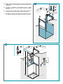
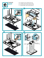
EN - Low ceiling installation. Securing of the bottom trestle and the
motor chamber to the ceiling(14) NRS pipe installation (15).
FR - Installation sur plafonds bas. Fixation support inférieur et
chambre moteur au plafond (14). Installation tube NRS (15).
ES - Instalación del techos bajos. Fijación estructura inferior y cáma-
ra de motor al techo (14). Instalación tubo NRS (15).
IT - Installazione con sotti bassi. Fissaggio traliccio inferiore e ca-
mera motore al sotto (14). Installazione tubo NRS (15).
2
3
V3
x 3
1
14
15

13
EN - Chimney installation: ceiling (16), false ceiling (17), low ceil-
ing (18).
FR - Installation conduit d’évacuation: sur plafond (16), faux-pla-
fond (17) et plafond bas (18).
ES - Instalación chimenea: en techo (16), en falso techo (17), en
techo bajo (18).
IT - Installazione camino: a sotto (16), a controsotto (17), a
sotto basso (18).
1
2
CEILING
FALSE CEILING
3
1
2
3
CEILING
x4
V5
1
2
3
16
17 18

14
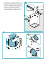
EN - Securing of the shelf (19). Lumina electric connection (20).
Assembly of lters and panel (21).
FR - Fixation panneau inférieur (19). Branchement électrique Lu-
mina (20). Montage ltres et panneau (21).
ES - Fijación del estante (19). Conexión eléctrica Lumina (20).
Montaje de ltros y panel (21).
IT - Fissaggio mensola (19). Collegamento elettrico Lumina (20).
Montaggio ltri e pannello (21).
1
3
V5
5
6
2
4
ONLY
LUMINA
1
2
1
2
3
4
19
20 21

15
22 23
2524
3
1
2
2
1
min38
3/8
- 975 mm
CEILING
SOFFITTO
H = 9
7/8
- 250 mm
A
NRS
1
V3
x 3
2
2
1
1
EN - Installing the carbon-zeolite lter (optional)
FR - Installation du iltre charbon-zeolite (en option)
ES - Instalacion de iltro de carbon-zeolita (opcional)
IT - Installazione ltro carbone-zeolite (opzionale)
LUMINA NRS
OPTIONAL
KACL.961

16
PLANE NRS
OPTIONAL
KACL.961
1
2
26 27
2928
2
1
min38
3/8
- 975 mm
CEILING
SOFFITTO
H = 9
7/8
- 250 mm
A
NRS
1
V3
x 3
2
2
1
1
EN - Installing the carbon-zeolite lter (optional)
FR - Installation du iltre charbon-zeolite (en option)
ES - Instalacion de iltro de carbon-zeolita (opcional)
IT - Installazione ltro carbone-zeolite (opzionale)

17
ENGLISH
SAFETY INSTRUCTIONS
AND WARNINGS
Installation operations are to be carried
out by skilled and qualied installers in ac-
cordance with the instructions in this book-
let and in compliance with the regulations in
force.
DO NOT use the hood if the power supply cable
or other components are damaged: disconnect
the hood from the electrical power supply and con-
tact the Dealer or an authorised Servicing Dealer for
repairs.
Do not modify the electrical, mechanical or func-
tional structure of the equipment.
Do not personally try to carry out repairs or re-
placements. Interventions carried out by incom-
petent and unauthorised persons can cause seri-
ous damage to the unit or physical and personal
harm, not covered by the Manufacturer's warran-
ty.
WARNINGS FOR THE INSTALLER
TECHNICAL SAFETY
Before installing the hood, check the in-
tegrity and function of each part. Should
anomalies be noted, do not proceed with
installation and contact the Dealer.
Do NOT install the hood if an aesthetic (or cos-
metic) defect has been detected. Put it back into
its original package and contact the dealer.
No claim can be made for aesthetic (or cosmetic)
defects once it has been installed.
During installation, always use personal protective
equipment (e.g.: Safety shoes) and adopt prudent
and proper conduct.
The installation kit (screws and plugs) supplied with
the hood is only to be used on masonry walls: in case
of installation on walls of a different material, assess
other installation options keeping in mind the type of
wall surface and the weight of the hood (indicated on
spec sheets at the beginning of this manual).
Keep in mind that installations with different types of
fastening systems from those supplied, or which are
not compliant, can cause electrical and mechanical
seal danger.
Do not install the hood outdoors and do not expose
it to atmospheric elements (rain, wind, etc.).
ELECTRICAL SAFETY
The electrical system to which the hood is
to be connected must be in accordance
with local standards and supplied with
earthed connection in compliance with safety
regulations in the country of use. It must also
comply with local standards regarding radio anti-
static properties.
Before installing the hood, check that the electrical
mains power supply corresponds with what is report-
ed on the identification plate located inside the hood.
The socket used to connect the installed equipment
to the electrical power supply must be within reach:
otherwise, install a mains switch to disconnect the
hood when required.
Any changes to the electrical system must be carried
out by a qualified electrician.
The maximum length of the flue fastening screws
(supplied by the manufacturer) must be ½" (13 mm).
Use of non-compliant screws with these instructions
can lead to danger of an electrical nature.
Do not try to solve the problem yourself in the event
of equipment malfunction, but contact the Dealer or
an authorised Servicing Department for repairs.
When installing the hood, disconnect
the equipment by removing the plug or
switching o the main switch.
FUMES DISCHARGE SAFETY
Do no connect the equipment to discharge
pipes of fumes produced from combustion
(for example boilers, replaces, etc.).
Before installing the hood, ensure that all standards in
force regarding discharge of air out of the room have
been complied with.
USER WARNINGS
These warnings have been drawn up for
your personal safety and those of others.
You are therefore kindly asked to read the
booklet carefully in its entirety before using the
or cleaning the equipment.
The Manufacturer declines all responsibility for
any damage caused directly, or indirectly, to per-
sons, things and pets as a consequence of failing
to comply with the safety warnings indicated in
this booklet.
It is imperative that this instructions booklet is
kept together with the equipment for any future
consultation.
If the equipment is sold or transferred to another per-
son, make sure that the booklet is also supplied so
that the new user can be made aware of the hood's
operation and relative warnings.
After the stainless steel hood has been installed, it

18
will need to be cleaned to remove any residues re-
maining from the protective coating as well as any
grease and oil stains which, if not removed, can cause
irreversible damage to the hood surface. To properly
clean the unit, the manufacturer recommends using
the supplied moist wipes, which are also available
sold separately.
Insist on original spare parts.
State of California Proposition 65 Warning
(US only)
WARNING
This product contains chemicals known to the State
of California to cause cancer and birth defects or oth-
er reproductive harm.
For more information go to www.P65Warnings.ca.gov
INTENDED USE
The equipment is solely intended to be used to
extract fumes generated from cooking food in
non-professional domestic kitchens: any other
use is improper. Improper use can cause damage
to persons, things, pets and exempts the Manu-
facturer from any liability.
The equipment can be used by children over the age
of 8 and by persons with reduced physical, sensory
and mental abilities, or with no experience or knowl-
edge, as long as they do so under supervision or after
having received relative instructions regarding safe
use of the equipment and understanding of the dan-
gers connected to it.
Children are not to play with the equipment. Clean-
ing and maintenance by the user must not be carried
out by children without supervision.
USE AND CLEANING WARNINGS
Before cleaning or carrying out mainte-
nance operations, disconnect the equip-
ment by removing the plug or switching
o the main switch.
Do not use the hood with wet hands or bare feet.
Always check that all electrical parts (lights, extractor
fan) are off when the equipment is not being used.
The maximum overall weight of any objects placed
or hung (if applicable) on the hood must not exceed
3lb 5oz (1.5 Kg).
Always supervise the cooking process during the use
of deep-fryers: Overheated oil can catch fire.
Do not leave open, unattended flames under the
hood.
Do not prepare food over an open flame under the
hood.
Never use the hood without the metal anti-grease
filters: in this case, grease and dirt will deposit in the
equipment and compromise its operation.
Accessible parts of the hood can be hot when used at
the same time as the cooking appliances.
Do not carry out any cleaning operations when parts
of the hood are still hot.
There can be a risk of fire if cleaning is not carried out
according to the instructions and products indicated
in this booklet.
Disconnect the main switch when the equipment is
not used for long periods of time.
If other appliances that use gas or other fu-
els are being used at the same time (boiler,
stove, replaces, etc.), make sure the room
where the fumes are discharged is well-ventilat-
ed, in compliance with the local regulations.
INSTALLATION
Intended only for qualied personnel
Before installing the hood, carefully read the section 'SA-
FETY INSTRUCTIONS AND WARNINGS'.
TECHNICAL FEATURES
The technical specifications are exhibited on the labels located inside
the hood.
POSITIONING
The minimum distance between the highest part of the cooking
equipment and the lowest part of the hood is indicated in the in-
stallation instructions.
Should the instructions for the gas cooker specify a greater distance,
this must be taken into consideration.
Do not install the hood outdoors and do not expose it to outdoor envi-
ronment (rain, wind, etc.).
ELECTRICAL CONNECTION
(Intended only for qualied personnel)
Disconnect the equipment from electrical mains power
supply before carrying out any operations on the hood.
Ensure that the wires inside the hood are not disconnected
or cut:
in the event of damage, contact your nearest Servicing Depart-
ment.
Refer to qualied personnel for electrical connections.
Connection must be carried out in compliance with the provisions
of law in force.
Before connecting the hood to the electrical mains power supply,
check that:
• voltage supply corresponds with what is reported on the data plate
located inside the hood;
• the electrical system is compliant and can withstand the load (see
the technical specifications located inside the hood);
• the power supply plug and cable do not come into contact with
temperatures exceeding 158°F (70 °C);
• the power supply system is effectively and properly connected to
earth in compliance with regulations in force;
•
the socket used to connect the hood is within reach.
In case of:
• devices fitted with cables without a plug: the type of plug to use is
a ''standardised'' one. The wires must be connected as follows: yel-

19
ENGLISH
low-green for grounding, blue for neutral and brown for the live. The
plug must be connected to an adequate safety socket.
•
fixed equipment not provided with a power supply cable and plug,
or any other device that ensures disconnection from the electrical
mains, with an opening gap of the contacts that enables total discon-
nection in overvoltage category III conditions.
Said disconnection devices must be provided in the mains power
supply in compliance with installation regulations.
The cable must not be cut off by the switch.
The Manufacturer declines all responsibility for failure to comply with
the safety regulations.
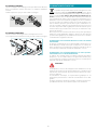
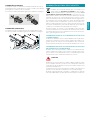
FUMES DISCHARGE
EXTERNAL EXHAUST HOOD SUCTION
In this version the fumes and vapours are discharged
outside through the exhaust pipe.
To this end, the hood outlet fitting must be connected
via a pipe, to an external output.
The outlet pipe must have:
• a diameter not less than that of the hood fitting.
• a slight slope downwards (drop) in the horizontal sections to prevent
condensation from flowing back into the motor.
• the minimum required number of bends.
• the minimum required length to avoid vibrations and reduce the
suction performance of the hood.
You are required to insulate the pipes if it passes through cold envi-
ronments.
In the presence of motors with 500 CFM or higher, a check valve is
present to prevent external air flowing back.
HOOD WITH INTERNAL RECIRCULATION FILTERING
In this model, the air passes through the charcoal filters
to be purified and recycled in the environment.
Ensure that the active carbon filters are assembled into
the hood, if not, install them as indicated in the assem-
bly instructions.
In this version the check valve must not be assembled: remove
it if it is on the air outlet fitting of the motor.
ASSEMBLY INSTRUCTIONS
Intended only for qualied personnel
The hood can be installed in various congurations.
The generic assembly steps apply to all installations; for
each case, follow the specic steps provided for the re-
quired installation.
OPERATION
WHEN TO TURN ON THE HOOD?
Switch on the hood at least one minute before starting to cook to direct
fumes and vapours towards the suction surface.
After cooking, leave the hood operating until complete extraction of all
vapours and odours. By means of the Timer function, it is possible to set
auto switch-off function which will allow the hood to turn off automat-
ically after 15 minutes of operation.
WHICH SPEED IS TO BE SELECTED?
1st speed: maintains the circulation of clean air with low electricity
consumption.
2nd speed: normal conditions of use.
3rd speed: presence of strong odours and vapours.
4th speed: rapid disposal of odours and vapours.
WHEN SHOULD THE FILTERS BE WASHED OR REPLACED?
The metal filters must be cleaned every 30 hours of operation.
The active carbon filters must be replaced every 3-4 months, depend-
ing on the use of the hood.
For further details refer to the “MAINTENANCE” section.
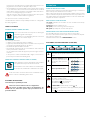
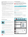
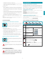
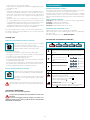
ELECTRONIC PUSHBUTTON PANEL
(PLANE NRS)
Motor ON/OFF
Upon start-up, the speed is that stored at the previous op-
eration.
Increase speed from 1 to 4
Speed 4 is only active for a
few minutes, then speed 3
activates.
The speeds are indicated by
the LEDs on the keys:
Speed 1
Speed 2
Speed 3
Speed 4
("+" LED flashing)
Reduce speed from 4 to 1
Light on/o
TIMER (red LED flashing)
Auto switch-off after 15 min.
The function deactivates (red LED off) if:
- The TIMER key (
) is pressed again.
- The ON/OFF key ( ) is pressed.
FILTER ALARM (red LED steady on with ( ) off)
Anti-grease filter maintenance after approximately 30 hours
of operation.
Press ( ) the meter for 3 seconds to reset.

20
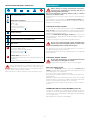
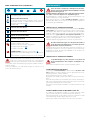
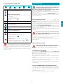
TOUCH PUSHBUTTON PANEL (LUMINA NRS)
ON/OFF (Blue led steady on)
Motor on/off and Speed 1
ON/OFF (blue led ashing)
If pressed for more than 3 seconds, it activates the 24h cycle
(1h ON -> 3h
OFF -> 1h ON)
the function deactivates if:
- The motor turns off (key )
- After 24h
Speed 2 activation
Speed 3 activation
Speed 4 activation for a few minutes only
Light on/o
TIMER (Red LED flashing)
Auto switch-off after 15 min.
The function deactivates (red LED off) if:
- The motor turns off (key
).
- The speed is changed.
FILTER ALARM (red LED steady on)
Anti-grease filter maintenance after approximately 30 hours
of operation.
Press the meter for 3 seconds to reset.
If the pushbutton panel is completely inactive, before con-
tacting the Technical assistance service, disconnect power
temporarily to the appliance (about 5“), possibly by acting on
the main switch, to restore normal operation.
If this measure has no effect, contact the Technical assistance service.
MAINTENANCE
Before cleaning or carrying out maintenance operations,
disconnect the equipment by removing the plug or
switching o the main switch.
Do not use detergents containing abrasive, acidic or corrosive
substances or abrasive cloths.
Regular maintenance guarantees proper operation and performance
over time.
Special attention is to be paid to the metal anti-grease lters : fre-
quent cleaning of the filters and their supports ensures that no flamma-
ble grease is accumulated.
CLEANING OF EXTERNAL SURFACES
You are advised to clean the external surfaces of the hood at least once
every 15 days
to prevent oily substances and grease from sticking to
them. To clean the brushed stainless steel hood, the Manufacturer rec-
ommends using "Magic Steel" wipes.
Alternatively and for all the other types of surfaces, it can be cleaned
using a damp cloth, slightly moistened with mild, liquid detergent or
denatured alcohol.
Complete cleaning by rinsing well and drying with soft cloths.
Do not use too much moisture or water around the push
button control panel and lighting devices in order to pre-
vent humidity from reaching electronic parts.
The glass panels can only be cleaned with specific, non-corrosive or
non-abrasive detergents using a soft cloth.
The Manufacturer declines all responsibility for failure to comply with
these instructions.
CLEANING OF INTERNAL SURFACES
Do not clean electrical parts, or parts related to the motor
inside the hood, with liquids or solvents.
For the internal metal parts, see the previous paragraph.
METAL ANTI-GREASE FILTERS
It is advised to frequently wash the metal filters (at least once a
month) leaving them to soak in boiling water and cleaning solution for
1 hour, taking care not to bend them.
Do not use corrosive, acid or alkaline detergents.
Rinse them well and wait for them to be completely dry before reas-
sembling them.
Washing in a dishwasher is permitted, however, it may cause the filter
material to darken: to reduce the possibility of this problem from hap-
pening, use low-temperature washes (131°F / 55°C max.).
To extract and insert the metal anti-grease filters see the assembly in-
structions.
CARBON AND ZEOLITE FILTERS (OPTIONAL) KACL.961
In normal use conditions, we recommend regenerating the zeolite-car-
bon filter every 9 months and replacing it after 18 months. Simply place
it in a domestic oven at a temperature of 392°F (200°C) for approximately
1 hour to regenerate it.
Wait until the filter cools before reassembling it.
La pagina sta caricando ...
La pagina sta caricando ...
La pagina sta caricando ...
La pagina sta caricando ...
La pagina sta caricando ...
La pagina sta caricando ...
La pagina sta caricando ...
La pagina sta caricando ...
La pagina sta caricando ...
La pagina sta caricando ...
La pagina sta caricando ...
La pagina sta caricando ...
La pagina sta caricando ...
La pagina sta caricando ...
La pagina sta caricando ...
La pagina sta caricando ...
La pagina sta caricando ...
La pagina sta caricando ...
La pagina sta caricando ...
La pagina sta caricando ...
-
 1
1
-
 2
2
-
 3
3
-
 4
4
-
 5
5
-
 6
6
-
 7
7
-
 8
8
-
 9
9
-
 10
10
-
 11
11
-
 12
12
-
 13
13
-
 14
14
-
 15
15
-
 16
16
-
 17
17
-
 18
18
-
 19
19
-
 20
20
-
 21
21
-
 22
22
-
 23
23
-
 24
24
-
 25
25
-
 26
26
-
 27
27
-
 28
28
-
 29
29
-
 30
30
-
 31
31
-
 32
32
-
 33
33
-
 34
34
-
 35
35
-
 36
36
-
 37
37
-
 38
38
-
 39
39
-
 40
40


Falmec FNLUM36I5SS Manuale utente
- Categoria
- Cappe da cucina
- Tipo
- Manuale utente
- Questo manuale è adatto anche per
in altre lingue
- English: Falmec FNLUM36I5SS User manual
- français: Falmec FNLUM36I5SS Manuel utilisateur
- español: Falmec FNLUM36I5SS Manual de usuario
Documenti correlati
-
Falmec FDLUM36I5SS Guida utente
-
-
-
-
-
-
-
-
-