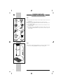
Foster CILINDRO ISLAND Installation Maintenance And Operating Instructions
- Categoria
- Cappe da cucina
- Tipo
- Installation Maintenance And Operating Instructions

Cappe d’arredo / HOODS
Forni / Built-in ovens
Lavelli / Sinks
Miscelatori / Faucets
Piani Cottura / Cooker hobs
Cappa/hood
codice/code 2530/000
CILINDRO
ISLAND


3
ISTRUZIONI PER L’INSTALLAZIONE,
LA MANUTENZIONE E L’USO DELLA
CAPPA MODELLO CILINDRO ISLAND
(cod. 2530/000)
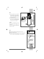
GENERALITÀ
Prima di installare e utilizzare la cappa, leg-
gere attentamente tutte le istruzioni riportate
nel seguente manuale.
Si raccomanda di conservare accuratamente
libretto e certificato di garanzia.
UTILIZZAZIONE
La cappa appartiene al tipo ASPIRANTE;
odori e vapori aspirati devono essere in un
condotto esterno di evacuazione.
È possibile trasformare la cappa in “Filtrante”
acquistando la confezione - Filtri in carbone
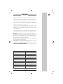
DIMENSIONI
DI MASSIMA
ITALIANO

4
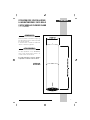
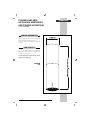
OPERAZIONE N°1
-1A- Tagliare le due reggette in plastica e il nastro adesivo ed aprire
completamente le falde della scatola.
-1B- Togliere il polistirolo P ed adagiarlo vicino alla scatola.
-1C- Ruotare completamente la scatola in modo che la parte inferiore
della cappa appoggi sul polistirolo P.
-1D- Svitare le due viti Y e liberare la cappa dal pannello truciolare T.
-1E- Svitare le due viti Z che fissanno il tubo superiore alla struttura
interna. N.B.: tenere con le mani il tubo superiore e farlo scorerre
verso il basso.
OPERAZIONE N°2
-2A- Controllare l’altezza occorrente dal soffitto al filo inferiore cappa
lasciando 650/700 mm. dal piano delle griglie dei fuochi
IT
ISTRUZIONI DI MONTAGGIO
CAPPA CILINDRO ISLAND
P
P
P
P
Y
T
Z
Z
650/ 700
Fig. 1
Fig. 2

5
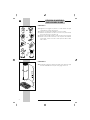
OPERAZIONE N°3
-3A- Riportare la misura desiderata * di
cui al punto 2A tra il filo inferiore
cappa e la parte superiore della
struttura scorrevole tirandola verso
l’alto dopo aver tolto le viti V che,
bloccano in posizione, la truttura in-
terna.
-3B- Fissare la struttura, nella posizione
desiderata, con le viti V n° 2 per lato
= totale n° 8. N.B.: vi sono 3 fori
per lato, il foro al centro non si deve
utilizzare.
--Attenzione:
- i fori sulla struttura sono a passo 15
mm. e quindi occorre usare quelli più
vicini alla misura desiderata;
- è indicata, con apposito cartello, la mi-
sura MAX in altezza che si può ottenere
garantendo la rigidità della struttura.
OPERAZIONE N°4
-4A- Trovare il centro di fissaggio della cappa sul soffitto.
-4B- Usare l’apposita maschera per segnare i 4 centri di foratura.
-4C- Forare con punta da 10 mm.
-4D- Inserire i Fischer ed avvitare le speciali barre filettate con l’ap-
posito inserto “CHIAVE TORX” T in dotazione.
IT
Fig. 3
Fig. 4
V
V
*
FISHER Ø 10
Ø 380

6
OPERAZIONE N°5
-5A- Portare la cappa verso il soffitto, inserire la struttura superiore
nelle barre filettate e bloccare con le rondelle e dadi Y.
Attenzione: bloccare con doppi dadi in modo da impedire l’allen-
tamento dovuto ad eventuali vibrazioni.
OPERAZIONE N°6
-6A- Effetttuare il collegamento del tubo di evacuazione fumi ed elet-
trico.
-6B- Portare il tubo scorrevole verso l’alto e bloccare con le viti Z.
La ditta costruttrice declina ogni responsabilità per il mancato rispetto di
queste istruzioni di montaggio.
La ditta costruttrice si riserva di apportare qualsiasi modifica senza pre-
avviso.
Fig. 5
Fig. 6
IT

7
COLLEGAMENTO ELETTRICO:
Prima di effettuare qualsiasi collegamento assicurarsi che la tensione
di rete corrisponda a quella riportata sull’etichetta posta all’interno
dell’apparecchio. Si consiglia di affidare il collegamento elettrico ad
un tecnico qualificato.
Apparecchio sprovvisto di spina: applicare una spina a norme oppure
un interruttore omnipolare a norme con una distanza dei contatti in
apertura non inferiore a 3 mm. Il cavo di terra non deve essere inter-
rotto dall’interruttore.
Si declina ogni responsabilità per inconvenienti derivanti dall’inosservan-
za delle suddette disposizioni.
La ditta costruttrice si riserva di apportare qualsiasi modifica senza pre-
avviso.
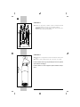
PANNELLO DI COMANDO:
Il pannello di comando è di tipo elettronico ed è posizionato nella
parte anteriore della cappa.
FUNZIONE TASTI:
Accensione e spegnimento luci.
0/1 Accensione 1a velocità e spegnimento motore.
2 Accensione 2a velocità.
3 Accensione 3a velocità.
4 Accensione 4a velocità.
NOTE:
- Dopo 30 ore di funzionamento della cappa i led dei “tasti 1, 2, 3,
4” lampeggiano per 30 secondi a motore spento per segnalare la
necessità della pulizia dei Filtri.
N.B.: premendo “a lungo” il tasto “velocità 3”, a motore spento,
l’allarme viene RESETTATO.
- Il bordo perimetrale dei tasti rimane sempre illuminato. Per disatti-
varlo premere “a lungo” il tasto “velocità 1” a motore spento.
N.B.: per riattivare l’illuminazione premere sempre “a lungo” il tasto
“velocità 1 ”.
- È possibile ritardare, automaticamente, lo spegnimento del motore
premendo “a lungo” uno dei tasti delle velocità. Il motore rimarrà
acceso per 10 minuti.
Fig. 7
IT
4
3
2
0/1

8
Scollegare l’apparecchio dalla rete elettrica prima di effettuare qual-
siasi operazione di manutenzione.
1) Pulizia delle parti di acciaio inox: al fine di evitare graffi sulle su-
perfici si sconsiglia l’uso di polveri abrasive o spazzole. Utilizzare
detergenti liquidi specifici per acciaio inox.
2) Pulizia del filtro: smontare il filtro agendo sulla maniglia e lavarlo
in lavastoviglie o con acqua saponata, evitando di strofinare con
panni o spugne. Prima di riporre il filtro asciugarlo accuratamente.
IT
MANUTENZIONE

9
- L’aria espulsa non deve essere convogliata in condotti che siano con-
divisi da altri apparecchi alimentati con energia diversa da quella
elettrica (es. stufe a legna, stufa gas, caldaie a combustibili...).
- Qualora l’utilizzo della cappa sia contemporaneo ad altri apparec-
chi, alimentati con energia diversa da quella elettrica, dovrà essere
prevista un’adeguata aerazione del locale.
- È da escludere l’impiego di fiamma libera sotto la cappa o la pre-
parazione di cibi alla fiamma poichè potrebbe dar luogo ad incendi.
Controllare che l’olio non si surriscaldi durante le fritture onde evi-
tare che prenda fuoco.
- L’inosservanza delle norme di pulizia dei filtri comporta rischi d’in-
cendio. Si raccomanda quindi di attenersi alle istruzioni suggerite.
IMPORTANTE: il montaggio della cappa in presenza di altri apparecchi
non elettrici (es. stufa a legna, stufa gas, caldaie a combustibili...) do-
vrà prevedere uno scarico esterno che assicuri una buona aerazione.
Verificare le condizioni del camino di scarico nel caso in cui quest’ul-
timo sia rimasto inutilizzato per molto tempo.
Ricordarsi inoltre di prestare la massima attenzione alle locali norme
vigenti in materia di evacuazione fumi.
Tutti i suggerimenti forniti al riguardo devono essere scrupolosamente
osservati al fine di evitare spiacevoli inconvenienti.
IL COSTRUTTORE DECLINA OGNI RESPONSABILITÀ DERIVATE DAL MANCA-
TO RISPETTO DELLE INDICAZIONI FORNITE.
ATTENZIONE
Codice
Dimensioni
Portata
Illuminazione Piano
Filtri anti-grasso inox
Velocità d’esercizio
Funzionamento
Finiture
Diametro foro espulsione Aria
Tenzione
Frequenza
Potenza massima assorbita
2530 000
Ø 380 x 920 -1330 mm
930 m
3
/h
4 faretti LED - 1,2x4 W
1
4
Aspirante
Inox
Ø 120-150 mm
220 - 240 V
50 Hz
324,8 W
IT


11
CILINDRO ISLAND HOOD
INSTALLATION, MAINTENANCE
AND OPERATING INSTRUCTIONS
(code 2530/000)
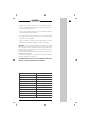
GENERAL INFORMATION
Carefully read the instructions in this manual
before installing and using the hood.
Keep this manual and warranty certificate
carefully.
HOW TO USE IT
This is an EXTRACTION hood. Extracted
odours and steam must be conveyed to an
external evacuation duct.
It can be turned into a “filter” hood by purcha-
sing the Carbon filter pack.
MAXIMUM
SIZE
ENGLISH

12
STEP 1
-1A- Cut the two plastic straps and the tape and open up the box
completely.
-1B- Remove the polystyrene (P) and place it next to the box.
-1C- Rotate the box completely so that the bottom of the hood rests on
the polystyrene (P).
-1D- Unscrew the two screws (Y) and release the hood from the chip-
board panel (T).
-1E- Unscrew the two screws (Z) that secure the upper pipe to the
inner frame. PLEASE NOTE: use your hands to hold the pipe and
slide it down.
STEP 2
-2A- Check the required height from the ceiling to the bottom edge of
the hood, leaving 650/700 mm from the burner grids.
EN
CILINDRO ISLAND HOOD
ASSEMBLY INSTRUCTIONS
P
P
P
P
Y
T
Z
Z
650/ 700
Fig. 1
Fig. 2

13
STEP 3
-3A- Note the desired size * mentioned
in 2A between the bottom edge of
the hood and the top of the sliding
frame by pulling it upwards after re-
moving the screws (V) that lock the
inner frame into place.
-3B- Secure the frame in the desired po-
sition with the screws (V), 2 on each
side = 8 in total. PLEASE NOTE:
there are 3 holes on each side, do
not use the hole in the middle.
--Caution:
- the holes in the frame have a 15 mm
pitch, so use the ones closest to the
desired size;
- a suitable notice reports the MAX height
that can be obtained by ensuring the
rigidity of the frame.
STEP 4
-4A- Finding the central area to fix the hood to the ceiling.
-4B- Use the designated template to mark the centres of the 4 holes.
-4C- Drill with a 10 mm drill bit.
-4D- Insert the Fischer rods and tighten the special threaded rods
with the designated “TORX SPANNER” insert (T) supplied.
EN
Fig. 3
Fig. 4
V
V
*
FISHER Ø 10
Ø 380

14
STEP 5
-5A- Move the hood towards the ceiling, insert the top frame into the
threaded rods and lock into place with washers and nuts (Y).
Caution: lock with double nuts to prevent loosening due to vibra-
tion.
STEP 6
-6A- Connect the fumes pipe and carry out the electrical connection.
-6B- Move the sliding pipe upwards and block it with the screws (Z).
The manufacturer declines any responsibility for failure to follow these
assembly instructions.
The manufacturer reserves the right to make any changes without prior
notice.
Fig. 5
Fig. 6
EN

15
ELECTRICAL CONNECTION:
Before carrying out any connection, make sure the mains voltage
matches the one reported on the plate inside the appliance. We re-
commend asking a qualified technician to carry out the electrical con-
nection.
Appliance without a plug: fit a plug in line with safety standards or an
omnipolar switch in line with safety standards with at least 3 mm
between open contacts. The earth cable must not be interrupted by
the switch.
We decline any responsibility for inconveniences deriving from failure to
follow these instructions.
The manufacturer reserves the right to make any changes without prior
notice.
CONTROL PANEL:
This is an electronic control panel and it is located at the front of the
hood.
KEY FUNCTIONS:
Lights on/off.
0/1 Speed 1 on and motor off.
2 Speed 2 on.
3 Speed 3 on.
4 Speed 4 on.
NOTES:
- After 30 hours of hood operation, the LEDs for “keys 1, 2, 3, 4”
flash for 30 seconds with the motor off to report that the filters need
to be changed.
PLEASE NOTE: the alarm is RESET by pressing the “speed 3” key
and holding it for a “prolonged period of time”.
- The edges of the keys are always lit. Press the “speed 1” key with
the motor off and hold it down for a “prolonged period of time”.
PLEASE NOTE: to turn the lights back on, press the “speed 1” key
again and hold it down for a “prolonged period of time”.
- The motor’s switch-off can be automatically delayed by pressing one
of the speed keys and holding it for a “prolonged period of time”.
The motor will remain on for 10 minutes.
Fig. 7
EN
4
3
2
0/1

16
Disconnect the appliance from the mains before conducting any
maintenance work.
1) Cleaning stainless steel parts: do not use abrasive powder or bru-
shes to prevent scratching the surfaces. Use liquid detergents spe-
cifically designed for stainless steel.
2) Cleaning the filter: disassemble the filter by using the handle and
wash it in the dishwasher or with soap and water. Do not rub with
cloths or brushes. Dry the filter thoroughly before placing it back.
EN
MAINTENANCE

17
- Ejected air not must be conveyed into ducts shared with other ap-
pliances not powered electrically (e.g. wood-burning stoves, gas sto-
ves, fuel-operated boilers, etc.).
- If the hood is used with other appliances not powered electrically,
provide for adequate room ventilation.
- Do not use naked flames under the hood or cook food over a flame
as it might cause a fire. Make sure oil does not overheat when frying
to prevent it from catching fire.
- Failure to follow the cleaning rules for the filters might cause a fire.
Therefore, we recommend following the instructions provided.
IMPORTANT: if there are other appliances not powered electrically
when the hood is assembled (e.g. wood-burning stove, gas stove,
fuel-operated boilers, etc.), provide for an external outlet that ensures
good ventilation. Check the condition of the discharge outlet if it has
not been used for a long time.
In addition, you are required to strictly comply with local regulations
regarding smoke discharge.
All the advice provided in this regard must be meticulously followed
to prevent undesirable consequences.
THE MANUFACTURER DECLINES ANY RESPONSIBILITY DERIVING FROM
FAILURE TO COMPLY WITH THE INSTRUCTIONS PROVIDED.
CAUTION
Code
Size
Capacity
Worktop Lighting
Stainless steel grease filters
Operating speed
Operation
Finishes
Diameter of air ejection hole
Voltage
Frequency
Maximum power absorbed
2530 000
Ø 380 x 920 -1330 mm
930 m
3
/h
4 LED spotlights - 1.2x4 W
1
4
Extraction
Stainless steel
Ø 120-150 mm
220 - 240 V
50 Hz
324.8 W
EN


via M.S. Ottone, 18/20 - Brescello (RE)
ASSISTENZA TECNICA Tel. 0522/684450 - FAX . 686019 MAIL ser[email protected]
MAGAZZINO RICAMBI Tel. / FAX 0522/684300 MAIL [email protected]
-
 1
1
-
 2
2
-
 3
3
-
 4
4
-
 5
5
-
 6
6
-
 7
7
-
 8
8
-
 9
9
-
 10
10
-
 11
11
-
 12
12
-
 13
13
-
 14
14
-
 15
15
-
 16
16
-
 17
17
-
 18
18
-
 19
19
-
 20
20


Foster CILINDRO ISLAND Installation Maintenance And Operating Instructions
- Categoria
- Cappe da cucina
- Tipo
- Installation Maintenance And Operating Instructions
in altre lingue
- English: Foster CILINDRO ISLAND