Alto CS 1020 PE Operating Instructions Manual
- Categoria
- Spruzzatore di vernice
- Tipo
- Operating Instructions Manual
Questo manuale è adatto anche per

CS 1020 PE
CS 1020 DE
Betriebsanleitung ...................... 4
Operating Instructions ............ 18
Notice d'utilisation .................. 32
Gebruiksaanwijzing ................ 46
Driftsinstruks ........................... 60
Bruksanvisning ........................ 74
Driftsvejledning ....................... 89
Käyttöohje ............................. 102
Instrucciones de manejo ....... 117

Déclaration de conformité CE
Bellenberg, 23.09.1994
Wap Reinigungssysteme GmbH & Co.
Guido-Oberdorfer-Straße 2-8
D-89287 Bellenberg
Erzeugnis:
Typ:
Beschreibung:
Die Bauart des Gerätes entspricht
folgenden einschlägigen
Bestimmungen:
Angewendete harmonisierte
Normen:
Angwendete nationale Normen
und technische Spezifikationen:
ppa. Rau, Dipl. Ing. (FH)
Leitung Forschung und Entwicklung
Hochdruckreiniger
CS 1020 DE (6,7 kW)
CS 1020 PE (8,1 kW)
IP X5, Schutzklasse I, 50 Hz.
EG-Maschinenrichtlinie 89/392/EWG
EG-Niederspannungsrichtlinie 73/23/EWG
EG-Richtlinie EMV 89/336/EWG
EN 292
EN 60335-1, EN 60555-3
EN 50081
DIN EN 60335-1
E-DIN VDE 0700 T 265
IEC 335-2-79
Wap Reinigungssysteme GmbH & Co.
Guido-Oberdorfer-Straße 2-8
D-89287 Bellenberg
Produit:
Type:
Description:
La construction de l’appareil est
conforme aux réglementations
afférentes suivantes:
Normes harmonisées appliquées:
Normes nationales et spécifications
techniques appliquées:
ppa. Rau, Dipl. Ing. (FH)
Direction Recherche et Développement
Bellenberg, 23.09.1994
EU Declaration of Conformity Dichiarazione di conformità CE
Bellenberg, 23.09.1994
Wap Reinigungssysteme GmbH & Co.
Guido-Oberdorfer-Straße 2-8
D-89287 Bellenberg
Product:
Type:
Description:
The design of the unit corresponds
to the following pertinent
regulations:
Applied harmonised standards:
Applied national standards and
technical specifications:
ppa. Rau, Dipl. Ing. (FH)
Head of Research and Development
Wap Reinigungssysteme GmbH & Co.
Guido-Oberdorfer-Straße 2-8
D-89287 Bellenberg
Prodotto:
Tipo:
Descrizione:
La costruzione dell' apparecchio è
conforme alle seguenti direttive
specifiche:
Norme armonizzate applicate:
Norme nazionali applicate e
specifiche tecniche:
ppa. Rau, Dipl. Ing. (FH)
Direttore Ricerca e Sviluppo
Pulitrice ad alta pressione
CS 1020 DE (6,7 kW)
CS 1020 PE (8,1 kW)
IP X5, Classe di protezione I, 50 Hz.
Direttiva CE sulle macchine 89/392/EWG
Direttiva CE sulla bassa tensione 73/23/EWG
Direttiva CE sulla compatibilità 89/336/EWG
elektromagnetica
EN 292
EN 60335-1, EN 60555-3
EN 50081
DIN EN 60335-1
E-DIN VDE 0700 T 265
IEC 335-2-79
Bellenberg, 23.09.1994
Atestado de conformidad de la UE EG-Verklaring van overeenstemming
Bellenberg, 23.09.1994
Wap Reinigungssysteme GmbH & Co.
Guido-Oberdorfer-Straße 2-8
D-89287 Bellenberg
Producto:
Modelo:
Descripción:
La construcción de la máquina
corresponde a las siguientes
normas específicas:
Normas armonizadas aplicadas:
Normas nacionales aplicadas y
especificaciones técnicas:
ppa. Rau, Dipl. Ing. (FH)
Director Investigación y Desarrollo
Máquina de limpieza a alta presión
CS 1020 DE (6,7 kW)
CS 1020 PE (8,1 kW)
IP X5, Clase de protección I, 50 Hz.
R. de la UE para máquinas 89/392/EWG
R. de la UE para baja tensión 73/23/EWG
R. de la UE para la compati-
bilidad electromagnética 89/336/EWG
EN 292
EN 60335-1, EN 60555-3
EN 50081
DIN EN 60335-1
E-DIN VDE 0700 T 265
IEC 335-2-79
Wap Reinigungssysteme GmbH & Co.
Guido-Oberdorfer-Straße 2-8
D-89287 Bellenberg
Produkt:
Type:
Beschrijving:
De constructie van het apparaat
voldoet aan de volgende van
toepassing zijnde voorschriften:
Toegepaste geharmoniseerde
normen:
Toegepaste nationale normen en
technische specificaties:
ppa. Rau, Dipl. Ing. (FH)
Chef onderzoek en ontwikkeling
Hogedrukreiniger
CS 1020 DE (6,7 kW)
CS 1020 PE (8,1 kW)
IP X5, Beschermklasse I, 50 Hz.
EG-machinerichtlijn 89/392/EWG
EG-laagspanningsrichtlijn 73/23/EWG
EG-richtlijn EMV 89/336/EWG
EN 292
EN 60335-1, EN 60555-3
EN 50081
DIN EN 60335-1
E-DIN VDE 0700 T 265
IEC 335-2-79
Bellenberg, 23.09.1994
EG - Konformitätserklärung
Nettoyeur haute pression
CS 1020 DE (6,7 kW)
CS 1020 PE (8,1 kW)
IP X5, Classe de protection I, 50 Hz.
Directive CE relative aux machines 89/392/EWG
Directive CE relative à basse tension 73/23/EWG
Directive CE EMV 89/336/EWG
EN 292
EN 60335-1, EN 60555-3
EN 50081
DIN EN 60335-1
E-DIN VDE 0700 T 265
IEC 335-2-79
High Pressure Cleaner
CS 1020 DE (6.7 kW)
CS 1020 PE (8.1 kW)
IP X5, Protection class I, 50 Hz.
EC Machine Directive 89/392/EWG
EC Low-voltage Directive 73/23/EWG
EC EMV Directive 89/336/EWG
EN 292
EN 60335-1, EN 60555-3
EN 50081
DIN EN 60335-1
E-DIN VDE 0700 T 265
IEC 335-2-79
61429 23.09.94

Bellenberg, 23.09.1994
Wap Reinigungssysteme GmbH & Co.
Guido-Oberdorfer-Straße 2-8
D-89287 Bellenberg
Produto:
Modelo:
Descrição:
A construção da máquina
corresponde às seguintes normas
específicas:
Normas harmonizadas aplicadas:
Normas nacionais aplicadas e
especificações técnicas:
ppa. Rau, Dipl. Ing. (FH)
Diretor de Pesquisas e Desenvolvimento
Máquina de limpeza de alta pressão
CS 1020 DE (6,7 kW)
CS 1020 PE (8,1 kW)
IP X5, Classe de protecção I, 50 Hz.
Directiva UE para máquinas 89/392/EWG
Directiva UE para baixa tensão 73/23/EWG
Directiva para a compatibilidade
electromagnética 89/336/EWG
EN 292
EN 60335-1, EN 60555-3
EN 50081
DIN EN 60335-1
E-DIN VDE 0700 T 265
IEC 335-2-79
Atestado de
conformidade da UE
Bellenberg, 23.09.1994
Wap Reinigungssysteme GmbH & Co.
Guido-Oberdorfer-Straße 2-8
D-89287 Bellenberg
Προϊόν:
Τύπος:
Περιγραφή:
Ο κατασκευαστικός τύπος της
συσκευής ανταποκρίνεται στους
ακόλουθους σχετικούς
κανονισµούς:
Εφαρµοσθείσες εναρµονισµένες
προδιαγραφές:
Εφαρµοσθείσες εθνικές
προδιαγραφές και τεχνικοί
προσδιορισµοί:
∆ιπλ. µηχ. A. Rau
Υπεύθυνος ερευνητικού τµήµατος
Μηχανή καθαρισµού υψηλής πίεσης
CS 1020 DE (6,7 kW)
CS 1020 PE (8,1 kW)
IP X5, Κατηγορία προστασίας I, 50 Hz.
Οδηγία περί µηχανών ΕΟΚ 89/392/ΕΟΚ
Οδηγία χαµηλών τάσεων ΕΟΚ 73/23/ΕΟΚ
Οδηγία περί ηλεκτροµαγνητικής
συµβατότητας 89/336/ΕΟΚ
EN 292
EN 60335-1, EN 60555-3
EN 50081
DIN EN 60335-1
E-DIN VDE 0700 T 265
IEC 335-2-79
∆ήλωση ανταπόκρισης ΕΟΚ
Bellenberg, 23.09.1994
Wap Reinigungssysteme GmbH & Co.
Guido-Oberdorfer-Straße 2-8
D-89287 Bellenberg
Produkt:
Type:
Beskrivelse:
Apparatets konstruksjonstype er i
samsvar med følgende gjeldende
bestemmelser:
Anvendte harmoniserte standarder:
Anvendte nasjonale standarder og
tekniske spesifikasjoner:
ppa. Rau, Dipl. Ing. (FH)
Leder forskning og utvikling
Høytrykks-rengjøringsapparat
CS 1020 DE (6,7 kW)
CS 1020 PE (8,1 kW)
IP X5, Beskyttelsesklasse I, 50 Hz.
EF-maskindirektiv 89/392/EEC
EF-lavspenningsdirektiv 73/23/EEC
EF-direktiv elektromagnetisk
kompatibilitet 89/336/EEC
EN 292
EN 60335-1, EN 60555-3
EN 50081
DIN EN 60335-1
E-DIN VDE 0700 T 265
IEC 335-2-79
EF-konformitetserklæring
Bellenberg, 23.09.1994
Wap Reinigungssysteme GmbH & Co.
Guido-Oberdorfer-Straße 2-8
D-89287 Bellenberg
Produkt:
Typ:
Beskrivning:
Apparatens konstruktion motsvarar
följande tillämpliga bestämmelser:
Tillämpade harmoniserade normer:
Tillämpade nationella normer och
tekniska specifikationer:
ppa. Rau, Dipl. Ing. (FH)
Ledare för forskning och utveckling
Högtryckstvätt
CS 1020 DE (6,7 kW)
CS 1020 PE (8,1 kW)
IP X5, Skyddsklass I, 50 Hz.
EG-maskindirektiv 89/392/EWG
EG-lågspänningsdirektiv 73/23/EWG
EG-direktiv EMK 89/336/EWG
EN 292
EN 60335-1, EN 60555-3
EN 50081
DIN EN 60335-1
E-DIN VDE 0700 T 265
IEC 335-2-79
EG-försäkran om
överensstämmelse
Bellenberg, 23.09.1994
Wap Reinigungssysteme GmbH & Co.
Guido-Oberdorfer-Straße 2-8
D-89287 Bellenberg
Produkt :
Type :
Beskrivelse:
Konstruktionen af dette apparat
opfylder følgende gældende
bestemmelser:
Anvendte harmoniserede
standarder:
Anvendte tyske standarder og
tekniske specifikationer:
ppa. Rau, Dipl. Ing. (FH)
Leder forskning og udvikling
Højtryksrenser
CS 1020 DE (6,7 kW)
CS 1020 PE (8,1 kW)
IP X5, Beskyttelsesklasse I, 50 Hz.
EF-maskindirektiv 89/392/EØF
EF-lavspændingsdirektiv 73/23/EØF
EF-direktiv vedr. elektromagnetisk
fordragelighed 89/336/EØF
EN 292
EN 60335-1, EN 60555-3
EN 50081
DIN EN 60335-1
E-DIN VDE 0700 T 265
IEC 335-2-79
EF-overensstemmelsesattest
Bellenberg, 23.09.1994
Wap Reinigungssysteme GmbH & Co.
Guido-Oberdorfer-Straße 2-8
D-89287 Bellenberg
Tuote:
Tyyppi:
Kuvaus:
Tämän laitteen rakenne vastaa
seuraavia määräyksiä:
Käytetyt harmonisoidut normit:
Käytetyt kansalliset normit ja
tekniset spesifikaatiot:
ppa. Rau, Dipl. Ing. (FH)
Kehitys- ja tutkimusjohtaja
Korkeapainepesuri
CS 1020 DE (6,7 kW)
CS 1020 PE (8,1 kW)
IP X5, Suojaluokka I, 50 Hz.
EY-konedirektiivi 89/392/EWG
EY-pienjännitedirektiivi 73/23/EWG
EY-direktiivi EMV 89/336/EWG
EN 292
EN 60335-1, EN 60555-3
EN 50081
DIN EN 60335-1
E-DIN VDE 0700 T 265
IEC 335-2-79
EY-Vaatimustenmukaisuusvakuutus

18
1 General Data
1.1 Important to bear in mind
These Operting Instructions should be handed to the personnel attending your Wap Machine. If these instructions are
closely adhered to ad observed, the machine will function unobjectionably, rendering you a perfect service.
You are asked to exclusively use Wap Cleaning and Care Agents, which are particulary attuned to match with Wap
machines. Times over again, we must ascertain that problems popping up in conjunction with the machine(s) , have
to be ascribed to the use of inappropriate products .
Please note: The warnings and safety advices of the producer of chemicals are to be closely followed ad abserved.
1.2 Intended Use
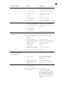
The Table below is to give you a survey over the numerous applications of these machines, as well as over the Wap
Cleaning and Care Agents specially developed and brought out to match these machines:
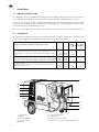
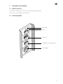
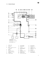
2 dosing valve 51 instrument board
5 motor 52 water outlet
11 pressure gauge 53 spray lance rest (clamp)
12 tap water feed 54 intake hose for cleaning and care agents
50 switch
50
23
2
11
51
53
5
54
52
31
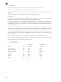
Unsuitable cleaners lead to poor cleaning results and may cause
damage to the machine. Predilute concentrate as described.
Quantity No. Usual
dilution
beforehand
pH-value in
1% solution
in tap water
ca.
WapClean Shampoo
Intensive action concentrate for removing dust, soot, grease, oil and insect
residues; suitable for sensitive surfaces. Demulsifying effect. Residuary oil content
<20 mg/l.
20 kg
220 kg
80848
80804
1:20 8,6
WapClean Intensive Cleaner
Cencentrate for universal application. Suitable for heavily soiled engines, machine
parts, halls, trucks, tarpaulins. Demulsifying effect. Residuary oil content <20mg/l.
20 kg
220 kg
80849
80748
1:10 8,8
WapClean Gloss Wax
Quick drying, with mineral oil base, for application after car wash. Provides a
weather-proof protective layer.
20 kg
220 kg
80850
80806
1:100 7,0

19
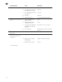
2 Description of the Machine
2.1 Machine Structure
Petrol-/diesel-operated machine, nonsystem-connected, mobile and protable
drive motor: refer operating instructions Honda
2.2 Operating Symbols
piston pump
burner
thermostat
cleaning and care agents dosing
pressure gauge

20
2.3 Function
The Functional Diagram (refer chapter 3 of this Manual) shows the machine‘s mode of action .
The Wap machine is divided into two (2) structural main groups, as follows:
structural main group I = drive motor with piston pump, regulation safety block with low water cut-off (flow
control)
structural main group II = heat exchanger with oil burner and temperature control
Functional Cycle:
The water feed is controlled via a foat valve. The Wap high pressure pump takes the water in, from the water tank,
pumping it, under pressure and through the heating coil, to the high pressure nozzle.
For sake of pressure control and pressure limitation, a regulation safety block is installed before the heating coil. Via
a dosing valve with automatic rinse , it is possible to add to the high pressure jet the desired cleaning and care agents.
Upon request, hot water can be produced by means of the fuel-oilheated heat exchanger. Water temperature is
controlled via a thermostat.
The fuel oil burner is fed with fuel oil via a fuel oil pump wich is flanged onto the oil burner motor. Fuel is injected,
under pressure, into the combustion chamber. A high pressure blower admits air for combustion. The igntion
transformer produces high voltage sparks at the ignition electrodes, which again provide for igniting the fuel.
Should the conveying capacity drop beneath a certain fixed value, then the burner is fully automatic disconnected.
Thus, the machine will never be overheated. As additional safety element, a thermal cutout is installed at the heat
exchanger‘s entry side.
When closing the trigger gun on/off, the fuel oil burner is switched off via the regulation safety block.
When actuating the trigger gun on/off, pressure drops, the regulation safety block again turns on the fuel oil burner.
Water quantity, pressure and temperature are infinitely variable.
2.4 Technical Data
CS 1020 PE CS 1020 DE
water jet l/h 860-400 860-400
working pressure bar 150-25 150-25
admiss. overpressure bar 200 200
admiss. temprerature °C 80/150 80/150
fuel oil tank l 30 30
length mm 1380 1380
height mm 840 840
width mm 740 740

21
CS 1020 PE CS 1020 DE
pressure
bar
nozzle type
spraying angle
15° 30° 60°
recoil
N
nozzle type
spraying angle
15° 30° 60°
recoil
N
high-pressure nozzle
130-150 *2505 26 *2505 26
110-130 25055 24 25055 24
95-110
1506 2506
5006
20
1506 2506
5006
20
75-95
1507 2507
5007
18
1507 2507
5007
18
* standard supplied nozzles
2.5 Nozzle Table
Only use the nozzles indicated on the table below. With high pressure hoses of lengths beyond 50 m, the next
size larger nozzle is to be applied. (f.ex.: instead of 2505, use 2506).
Depending on the kind and extent of dirt involved, and according to the cleaning job to be performed, the
appropriate high pressure nozzle(s) is(are) to be chosen.
The working pressure as such is pendent from the high pressure nozzle. The high pressure nozzle required can
be taken frem the TABLE below.
Please note: The pressures indicated under ‘Technical Data’, as well as those pressures mentioned in the nozzle
table hereunder, may deviate for the following reasons:
a) production tolerance(s) high pressure nozzles
b) speed deviation(s) of drive motor

22
3 Diagrams
3.1 Wiring Diagram
B1 thermostat
B3 thermal cutout
C1 operating capacitor
F2 fine-wire fuse (6,3A=5509)
F3 pressure switch
F4 low petrol cutoff (flow control)
G1 generator
K2 time relay (retarded fuel supply)
M1 motor pump
M2 motor burner
P1 working hour meter
Q1 master switch
T1 ignition transformer
X1 connector block
Y1 solenoid valve (fuel oil supply)

23
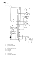
3.2 Schematic Diagram
11 pressure gauge
12 thermal cutout
13 fuel tank
14 ignition transformer
15 oil burner motor
16 oil filter
17 oil pump
18 high pressure blower
19 solenoid valve
20 ignition electrode
21 oil nozzle with strainer
*1 additives tank
2 dosing valve
3 filter
4 infinite regulation of pressure
and quantity
5 motor
6 generator
7 high pressure pump
8 regulation safety block
9 safety valve
10 hydraulic damper
22 heat exchanger
23 thermostat
24 trigger gun on/off
25 spray lance
27 high pressure nozzle
28 water tank
29 float valve
30 filter (float valve)
31 tap water feed
* special equipment
water
additive(s)
fuel

24
4 Operation of Machine - Safety Hints
Please always observe the Rules and Regulations applicable for ejectors of liquids (high pressure cleaners), and
applicable for the machine´s connection and operation.
Ejectors of liquids (high pressure cleaners) are only and exclusively to be operated by such persons who are well
familiar, and instructed, re. this type of work.
For UK: Guidance Note P.M. 29 from the Health and Safety Executive refers to Steam Water/Water Pressure
Cleaners.
Users should be aware of the provisions of the Health and Safety at Work Act 1974 , and of the Electricity Special
Regulations (Factories‘ Act) 1908 and 1944.
Copies of P.M. 29 can be obtained from: The health and Safety Executive, Bayards House, 1 Chepstow place,
London W 24 TF, or from HSE area offices.
In the following some excerpts from the German Directivs for Ejectors of Liquids (high pressure cleaners):
(by the way, these Directivs can be obtained, in complete edition, from the publishing house Carl Heymanns,
Luxemburger Strasse 229, D 5000 Cologne-41, Federal Republic of Germany)
‘ . . . .The manufacturer‘ s Operating instructions are to be closely adhered to and observed. The contractor/owner
is obliged to provide for a thorough check-up of the ejector’s essential components - such as of its safety organs
(pump , hoses , spray lance) - each time prior to starting operations, so as to be assured that these safety organs
are in perfect condition. Hoses are only allowed to be fixed by the manufacturer himself, respectively by the
supplier and/or an expert. Operators have to wear the necessary protcetive clothing.
The spray lance trigger gun on/off is not allowed to be fixed in position ‘ON’. When interrupting/stopping work,
the trigger gun locking device of the spray lance is to be blocked.
The machine complies with the German Directives for Ejectors of Liquids (high pressure cleaners) . . . . ‘
The machine’s water contents is less than 10 l (miniature-type steam boiler) . Boiler type and test pressure are
complying with the German Decree covering Steam Boilers. No admission of the design is required, nor an
announcement of permission, nor an acceptance test.
The machine has to be constantly controlled, so that the personnel attending it immediately will perceive any
absence of the flame .
When switching on the burner, never lean over the exhaust gas outlet! Danger of burning and danger of
fulmination! Machines being used in flammable areas, for example filling stations and/or other dangerous zones,
are only allowed to be run - due to the possible danger of an explosion - outside of the danger zones stipulated
by the TRbF (= Technical Rules for Combustible Liquids) .
Genuine Wap Spares are to be used only and exclusively!
Cables should be properly stored when not in use.
The machine should be used, whenever possible, on level ground.
Drainage of the working area should be good.
Care should be taken to avoid spillages.
Any equipment to be cleaned, and having an electrical supply, should be always, of course, disconnected, and
all terminals sealed, or otherwise protected against fluid penetration. Before re-connection, the equipment
should be checked by an elctrician.
Operators are to be trained to follow a safe working system, and should be informed of any potential hazards.
- Supervisors should ensure that operators always do follow the safe working system.
4.1 Tap Water Feed
Connect the machine with the water tap, by a water hose of 1/2” or 3/4" .
Minimum feed at 3-6 bar flow pressure - refer 2.3 (water jet) .

25
4.2 Putting into Operation
Prior to putting the machine into operation, cut off neck on oil filler plug.
Prior to starting with the Honda engine, read the Honda Operating Instructions!
Machine is supplied with an empty fuel tank.
Fill the fuel tank with fuel oil EL or Diesel oil DIN 51 603 (to be done on cold machine only!). The fuel oil must
be free from any impurities .
Additives tank (special accessory) is to be filled with Wap Cleaning and Care Agents, in the prescribed dilution(s)
. Open water tap. During the winter season, the machine will be supplied with an antifreeze in its water system.
For purging and de-aerating of the system, switch is to be turned on ‘piston pump’, the drive motor to be started,
and the machine allowed to run for about 1 minute. Stop machine. Refer Honda Operating Instructions.
Connect high pressure hose to spray lance. Be careful about the nozzle size, refer 2.5 - Nozzle Table.
To note:
The spray jet is likely to cause injuries whenever being handled inattentively and inexpertly. (Never direct the jet
against persons!) During the machine’s operation, recoil forces do occur at the spraying device (spray lance) , with
bent spray lance, there will be torgue additionally.
4.3 Operation
Cold Water:
Unlock, and actuate, trigger gun on/off, put switch on ‘piston pump‘, start the drive motor.
Hot Water:
(Level I) - refer Technical Data 2.4 -
Unlock, and actuate, trigger gun on/off, put switch on ‘piston pump’ , start drive motor. If a uniform jet emerges
from the high pressure nozzle , putt switch on ‘burner‘.
Steam Jet:
(Level II) -refer Technical Data 2.4 -
Exchange standard spray lance against the steam jet spray lance, ref. no.14786. Turn thermostat to stop (steam
jet) .
Pressure and quantity control to be opened anti-clockwise.
Unlock, and actuate, trigger gun on/off, put switch on ‘piston pump’ , start drive motor. If a uniform jet emerges
from the fan ja nozzle, then put switch on ‘burner’.
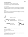
trigger gun on/off with coaxial spray
lance(special version)
trigger gun on/off with spray lance straight (standard
version) or bent (special version)
coaxial spray lance
turn handle clockwise =
full water quantity and full pressure
turn handle anti-clockwise =
reduced pressure at full water quantity
steam jet spray lance

26
Cleaning and Care Agents (Additives):
Choose dosage at dosing valve, according to the existing requirement, and set it.
Important to observe:
On all interruptions of operation, even very short ones, be sure to put the switch on ‘0’ and to release pressure
- this being of utmost importance!
Attention:
Do not allow the machine to be in operation - with closed trigger gun on/off - for more than 10 minutes, since
this would affect the high pressure pump.
Temperature is thermostat-controlled. This safety feature protects your machine from being overheated. If
temperature rises beyond the value adjusted, the burner disconnects fully automatic.
The pressure gauge indicates the working presse. If pressure increases beyond the working pressure as such
maybe the high presssure nozzle is clogged, or the machine has to be decalcified. If cleaning and care agents are
used, the bins containing them are cot allowed to get empty, since this would bring about intake of air.
Water quantity, pressure and temperature are infinitely variable.
Never pull, crush, twist and/or buckle the high pressure hose. Genuine Wap high pressure hoses are to be used
exclusively. They are complying with the ‘German Directives for Ejectors of Liquids (High pressure cleaners) ‘ .
Fittings and hoses are accordingly marked.
Please follow our Service Instructions (Maintenance) Chapter 5 of this Manual.
4.4 Stopping ration
Dosing valve on position "O" .
Switch on position "piston pump". Have machine run for about 1 minute, then move switch on "0".
Stop drive motor (refer Honda Operating Instructions). Actuate trigger gun on/off, until machine will be
depressurized.
Lock the trigger.
Close water-tap.
For operation during winter season:
Place machine into a frostproof room. Should this not be possible, please proceed as follows:
Close water-tap. Start drive motor. Actuate trigger gun on/off several times. At the same time, fill in an antifreeze
(appcox. 4 l) into water tank. Your machine is frostproof, as soon as antifreeze solution emerges from the spray
lance.
We recommend as follows:
At temperatures around the freezing point, the fuel starts to solidify (paraffine extraction). This may cause
problems re. the starting of the burner. We, therefore, recommend to add a special agent to the fuel thus
improving the solidifying and flowing properties. Such agents are available from professional fuel dealers. The
admixture being: 2l of the additive for approx. 1000l of fuel, to be made at emperatures higher than 8°C.
4.5 Inspections
Upon requirement - but at least every 12 months - the ejectors of liquids (high pressure cleaners) have to be
thoroughly checked over by experts, with regard to operational safety and reliability.
On machines standing idle, however, inspection may be deferred until the next start-up.
The instructions issued by the manufacturer are to be followed and adhered to. Our expert mechanics will be
available to you at any time. The results of inspections are always to be put down in writing.
The heating mechanism is al firing plant, which is to be checked over and controlled in conformity with the locally
prevailing Rules and Regulations.
A documented routine maintenance system consisting of regular inspection, testing and repair by a competent
person, should be established.

27
Earth continuity checks should be carried out on the machine, and on its fixed wiring installation, when the
equipment is installed, and at regular intervals afterwards.
4.6 Guarantee
Our General Terms of Sale and Delivery do prevail.
This Guarantee only covers proved defects of material and of workmanship.
In order to obviate non-justified claims, we are enumerating below those keypoints, which shall not be covered
by this Guarantee:
Damages caused by changing the machine´s adjustment.
Damages of transportation.
Damages due to careless handling by the orderer, or due to violence.
Damages caused by non-observance of our Decalcifying Instructions.
Damages caused by non-observance of our Operating Instructions.
Damages on products other than ours are handled according to the Guarantee of the respective manufacturer.
Damages occuring on hoses shall be only subject to guarantee if the manufacturer has recognized the damage
after examination.
Damages occuring on packings, seals, ignition electrodes, high pressure nozzles and other items, which are due
to normal wear.
5 Maintenance
5.1 Maintenance Plan - drive motor
Refer to Honda Operating Instructions
5.2 Maintenance Plan - high pressure pump
Every 40 hours of operation - at least once a week
Pump oil level control - control oil level regularly at dipstick of oil filler plug - if ncessary, refill with gear lubricant
oil. Change oil whenever it shows a greyish or white shade.
Clean filter (at water feed)
Clean filter (at pump)
Every 200 hours of operation - at least once every 3 months
Pump oil change - for inst. ARAL DEGOL BG 220, Shell Omala 220, Mobil Gear 630
V-belt tightening - if neccesary, regulate at generator
Igniter - ignition transformer, ignition cable, ignition electrodes (to e cleaned) , replace defective parts.
Oil nozzle - clean it.
Oil fiter - clean it.
Solenoid valve - clean it, clean strainer.
In case of necessity - but at least every 12 monts

28
Heat exchanger - to be cleaned once a year, with high pressure, through front side and rear-side clean-out hole.
Take dripping water hose out of the water tank.
Tank - to be emptied and cleaned.
5.3 Decalcification
Has to be performed regularly/periodically. Calcification is dependent from the water hardness as such, and is
indicated at the pressure gauge by a gradual increase of the water pressure. Decalcification has to be made once
the working pressure increases by 10 bar.
For decalcifying, please proceed as follows:
Open water-tap, unscrew high pressure nozzle from spray lance and dip/put it seperately into the decalcifying
agent.
Unscrew high pressure hose from water outlet tube. Put cleaning and care agents intake hose into the filled
decalcifying agent bin. Open dosing valve completely.
Start drive motor. The decalcifying agent is taken in and, after approx. 1 minute, it ‘bubbles’ out of the water
outlet tube (strong bubbling effect). Stop drive motor. Then take out cleaning and care agents intake hose from
the bin ontaining decalcifying agent, and put it into clear water.
After about 15 minutes, start drive motor. After about 2 further minutes, a uniform jet is to emerge from the
water outlet tube. Should this not be the case, then decalcify once again.
Screw high pressure nozzle onto the spray lance and re-connect the high pressure hose.
Caution!
The decalcifying agent causes burns. Avoid contact with eyes, skin, and clothing. Wear the prprer protective
clothing (for example gloves, facial protection, apron).
The machine is subject to the German Steam Boiler Decree, in accordance to which only such agents are to be
used which are officially admitted, as is, for example, the Wap decalcifying agent.
6 Trouble Shooting
6.1 General Remarks
Before working on the machine, the mains plug must be pulled, and the machine made depressurized.
Always proceed systematically. Trace the problem(s) /trouble(s) by aid of the wiring diagram and the functional
diagram.
Trouble/Problem Cause Elimination
A machine fails to start a) battery empty, defective charge battery or replace it (refer
operating instructions Honda)
B burner does not ignite when
being switched on
a) fuel tank empty fill up fuel tank
b) impurities or water in the fuel clean it
c) no ingnition spark adjust electrode gap - refer drwg. 6,
check ignition cable, ignition
electrodes. If necessary, replace parts,
recheck electrical connection
d) solenoid valve does not open check electr. connection, replace
solenoid valve
e) solenoid valve strainer dirty clean strainer - refer B b)

29
Trouble/Problem Cause Elimination
f) oil nozzle clogged clean nozzle and strainer, replace
if necessary - for cause, refer B b)
g) oil pump defective exchange it, for causes, refer Ba) - b)
*h) controller turned off for possible causes, refer B a) - h),
press supression button
*i) dirty probe clean it
j) not enough water for cause, refer D a) - g)
k) thermal cutout blown check for cause, eliminate cause, put
in new thermal cutout
C burner soots a) oil pressure too high,
consequently not enough air
supply, dirty blower wheel
cut oil pressure, have combustion
adjusted by your works mechanic,
clean heating coil if it is heavily
sootetd
b) for possible causes,
refer B b)e)f)g)h)
c) motor speed too low refer operatin instructions Honda
D burner disconnects during
operation
a) water-tap shut open it
b) not enough water qantity
available
re-check water pressure (refer 4.2)
c) float valve clogged clean valve and filter
d) suction and pressure valve of
high pressure pumpe
defective or dirty
dismount valves, clean and/or replace
these. Clean suction hose filter,
de-aerate the pumpe
e) filter clogged clean it
*f) cleaning and care agents bin
empty
re-fill it, de-aerate pump
g) filter of hp pump clogged clean it
E regulation safety block
switches over (at opened
trigger gun on/off)
a) high pressure nozzle dirty unscrew and clean it
b) machine calcified decalcify as per the respective
instructions (refer chapter 5.
maintanance)
c) wrong hp nozzle installed apply hp nozzle as per 2.4
d) regulation safety block
misadjusted
have it re-adjusted by the works
mechanic
F pressure too low a) cleaning and care agents
container* empty
fill it up
b) high pressure nozzle worn out renew it (refer 2.4)
c) air in the system refill cleaning an care agents
container*, retighten all screwing at
hp pump and additives lines (refer D
a) - f)), after trouble elimination,
unscrew hp hose from machine and
have pump run in depressureized
condition

30
Trouble/Problem Cause Elimination
d) V-belt tension too weak retighten V-belts
e) suction and pressure valve of
hp pump defective or dirty
refer D d)
f) pressure and quantity control
valve opened
close valve
g) filter dirty clean filter
h) motor speed too low refer operatin instructions Honda
G cleaning and care agents fail to
arrive
a) empty cleaning and care
agents container*
re-fill it
b) cleaning and care agents
container* silted up
clean it
c) suction valve at cleaning and
care agents feed dirty resp.
defectifve
disassemble it, clean rep. replace it
d) air in the system shut dosing valve, deaerate the pump,
refer F c)
H pump oil shows a greyish or
white shade
a) worn collars renew collars
I regulation safety block
constantly switches over (at
closed pistol)
a) trigger gun on/off untight renew it
b) high pressure screwing or
tubing untight
retighten screwing, seal tubing
c) high pressure hose leaky replace it
* special equipment

31
7 Safety Features
7.1 Regulation Safety Block with Low Water Cut-Off
Inadmissible excess pressure is returned to the pump´s intake line, via a py-pass bore and without residual
pressure, on the regulation safety block´s responding. The regulation safety block is set, adjusted and lead-sealed
by the manufacturer. It is not allowed to be reset.
Along with the Coaxial-spray lance, the regulation safety block renders possible an infinite adjustment of
pressure.
The low water cut-off, integradet in the regulation safety block, disconnects, whenever water is short, the fuel
supply to the oil burner. This is done via a solenoid valve. By this, the heat exchanger is not overheated.
7.2 Safety Valve
It serves the tastk to prevent inadmissible excess working pressure. On responding of the safety valve, the
escaping liquid is carried off without risk. The safety valve too is set, adjested and lead-sealed by the
manufacturer, an it is not to be re-set.
7.3 Thermal Cutout
The thermal cutout serves the task of disconnecting the machine, and of preventing its restarting, whenever a
safety feature fails to function, and, at the same time, water is short.
Important note:
Once the thermal cutout has been in action, the machine can only be restarted again after replacement of the
thermal cutout.

NOTIZEN

ALTO HEADQUARTERS
ALTO U.S. Inc.
390 South Woods Mill Road
Suite 300
Chesterfield
USA-Missouri 63017-3433
Tel.: (+1) 31 42 05 12 20
Fax: (+1) 31 42 05 15 44
SUBSIDIARIES/DIVISIONS
AUSTRALIA
ALTO Overseas Inc.
1B/8 Resolution Drive
P.O.Box 797
AUS-Caringbah, N.S.W. 2229
Tel: (++61) 295 24 61 22
Fax: (++61) 295 24 52 56
AUSTRIA
Wap Reinigungssysteme GmbH
Metzgerstr. 68
A-5101 Bergheim/Salzburg
Phone: (+43) 662 45 64 00-14
Fax: ( +43) 662 45 64 00-55
Mobil: (+43) 664 12 49 55 0
BRASIL
Wap do Brasil Ltda.
Rua 25 de Agosto, 608
Jardim Pinhais
CEP 83323-260 Pinhais/Paraná
BR-Brasil
Tel./Fax (+55) 41 86 74 02 6
CANADA
ALTO Canada
24 Constellation Road
Rexdale
C-Ontario M9W 1K1
Tel: 1 41 66 75 58 30
Fax: 1 41 66 75 69 89
CZECHIA
Wap čistící systémy s.r.o.
Zateckých 9
CZ-140 00 Praha 4
Tel. (++420) 02 / 42 78 38
Fax (++420) 02 / 42 19 25
Wap čistící systémy s.r.o.
Mucednícka 3
CZ-61600 Brno
Tel. (++420) 05 / 41 21 48 85
Fax (++420) 05 / 41 21 48 87
DENMARK
ALTO Danmark A/S
Industrikvarteret
DK-9560 Hadsund
Tel: (++45) 72 18 21 00
Fax: (++45) 72 18 21 05
ALTO Danmark A/S
(food division)
Blytækkervej 2,
DK-9000 Aalborg 10
Tel: (++45) 72 18 21 00
Fax: (++45) 72 18 20 99
FRANCE
ALTO France S.A.
B.P. 44, 4 Place d’Ostwald
F-67036 Strasbourg Cedex 2
Tel: (++33) 3 88 28 84 00
Fax: (++33) 3 88 30 05 00
GERMANY
Wap KundenCenter
Tel. (++49) 0180 / 5 37 37 37
Fax (++49) 0180 / 5 37 37 38
e-mail: [email protected]
Besuchen Sie uns im Internet:
http://www.wap-online.com
Wap-Zentrale Bellenberg
Hauptverwaltung
Wap Reinigungssysteme GmbH & Co
D-89287 Bellenberg
Guido-Oberdorfer-Straße 2-8
Tel. (++49) 07306 / 72-0
Fax (++49) 07306 / 7 22 00
RegionalCenter Frankfurt
D-63452 Hanau
Moselstraße 2b
Tel. (++49) 06181 / 18 72-0
Fax (++49) 06181 / 18 72-11
e-mail: [email protected]
RegionalCenter Hannover
D-29227 Celle
Wernerusstraße 25
Tel. (++49) 05141 / 95 55-0
Fax (++49) 05141 / 95 55-95
e-mail: [email protected]
RegionalCenter Köln
D-51145 Köln-Porz
Kaiserstraße 127
Tel. (++49) 02203 / 9 22 99-0
Fax (++49) 02203 / 9 22 99-25
e-mail: [email protected]
RegionalCenter Leipzig
D-04445 Leipzig-Liebertwolkwitz
An der Brauerei 5
Einfahrt Leipziger Straße 2
Tel. (++49) 034297 / 4 87 25
Fax (++49) 034297 / 4 93 57
e-mail: [email protected]
RegionalCenter München
D-85716 Unterschleißheim
Furtweg 11
Tel. (++49) 089 / 32 15 02-0
Fax (++49) 089 / 32 15 02-40
e-mail: [email protected]
RegionalCenter Stuttgart
D-71069 Sindelfingen
OT Darmsheim
Dornierstraße 7
Tel. (++49) 07031 / 76 70-0
Fax (++49) 07031 / 76 70-20
e-mail: [email protected]
RegionalCenter Ulm
D-89287 Bellenberg
Guido-Oberdorfer-Straße 2-8
Tel. (++49) 07306 / 72-195
Fax (++49) 07306 / 3 41 29
e-mail: [email protected]
GREAT BRITAIN
ALTO Cleaning Systems(UK)Ltd.
Gilwilly Industrial Estate
GB-Penrith, Cumbria CA11 9BN
Tel: (+44) 1 7 68 86 89 95
Fax: (+44) 1 7 68 86 47 13
Telex: 64309 kewg
ASIA
Alto Hong Kong
Representative Office
RM 602, Tower B, Regent Ctr.
70, Ta Chuen Ping Street
Kwai chung
HK-Hong Kong
Tel. (++852) 26 10 10 42
Fax (++852) 26 10 10 47
JAPAN
ALTO Danmark A/S Japan
Representative Office
Naruse-build 4F
7-2 Shinbashi 1-Chome, Minato-Ku
J-Tokyo 105-004
Tel: (+81) 3 35 69 38 07
Fax: (+81) 3 35 69 38 08
Wap Representative Office
Japan
25-6, Honode Cho
Adachi-Ku
J-Tokyo - 120-0021
Tel. (+81) 3 / 52 44 07 82
Fax (+81) 3 / 52 44 07 83
KROATIA
Wap sistemi za čišćenje, d.o.o.
HR-10000 Zagreb
Florijana Andrašeca 14
Tel. (++385) 01 / 3 09 49 07
(++385) 01 / 3 09 49 09
Fax (++385) 01 / 3 09 49 06
NETHERLANDS
WAP/ALTO Nederland B.V.
Stuartweg 4C,
NL-4131 NJ Vianen
Tel: (+31) (0) 3 47 32 40 00
Fax: (+31) (0) 3 47 32 40 01
Wap (NL) B.V.
NL-3371 MA Hardinxveld-
Giessendam
Transportweg 53-57
Postbus 65
Tel. (+31) 01846 / 1 81 44
Fax (+31) 01846 / 1 41 13
e-mail: [email protected]
NORWAY
ALTO Norge AS
Bjørnerudveien 24
Postboks 64, Bjørndal,
N-1266 Oslo
Tel: (+47) 22 75 17 70
Fax: (+47) 22 75 17 71
SINGAPORE
ALTO Danmark A/S
Representative Office
271 Bukit Timah Road
#04-11 Balmoral Plaza
SG-Singapore 259708
Tel: (+65) 8 36 64 55
Fax: (+65) 8 36 64 56
SLOWAKIA
Wap čistiace systémy spol. s.r.o.
SK-83237 Bratislava
Vajnorská 135
Tel. (++421) 7 44 25 96 64
Fax (++421) 7 44 25 79 44
SLOWENIA
Wap čistilni sistemi, d.o.o.
SLO-1110 Ljubljana
Letališka 33
Tel. (++0368) 61 44 23 42
Fax (++0368) 61 1 40 42 94
SOUTH AFRICA
Wap South Africa (Pty) Ltd.
ZA-Kempteon Park (T) 1620
P.O. Box 2122
Tel. (++27) 11 97 57 06 0
Fax (++27) 11 39 43 08 1
SPAIN
Hidrolimpia, S.L.
E-28760 Tres Cantos - Madrid
Ronda de Valdecarrizo 9
– Modulo 5 –
Tel. (++34) 091 / 804 62 56
Fax (++34) 091 / 804 64 63
SWEDEN
ALTO Sverige AB
Aminogatan 18, Box 40 29
S-431 04 Mölndal
Tel: (+46) 31 27 16 00
Fax: (+46) 31 87 24 19
SWITZERLAND
Wap Reinigungssysteme
(Schweiz) AG
CH-5042 Hirschthal / AG
Holzikerstraße 488
Tel. (++041) 062 / 7 39 32 50
Fax (++041) 062 / 7 39 32 51
Wap Reinigungssysteme
(Schweiz) AG
CH-1029 Villars-Ste-Croix
Zone industrielle
Croix du Péage
Tel. (++041) 021 / 6 35 32 74
Fax (++041) 021 / 6 35 32 75
USA
ALTO U.S.Inc
2100 Highway 265
Springdale
USA-Arkansas 72764
Tel: (+1) 50 17 50 10 00
Fax: (+1) 50 17 56 07 19
ALTO U.S.Inc
1100 Haskins Road
Bowling Green
USA-Ohio 43402
Tel: (+1) 41 93 52 75 11
Fax: (+1) 41 93 53 71 87
ALTO U.S.Inc
P.O.Box 4369
1500 North Belcher Road
Clearwater
USA-Florida 33765
Tel: (+1) 72 74 61 45 55
Fax: (+1) 72 74 61 51 93
64749 / 010500
-
 1
1
-
 2
2
-
 3
3
-
 4
4
-
 5
5
-
 6
6
-
 7
7
-
 8
8
-
 9
9
-
 10
10
-
 11
11
-
 12
12
-
 13
13
-
 14
14
-
 15
15
-
 16
16
-
 17
17
-
 18
18
-
 19
19


Alto CS 1020 PE Operating Instructions Manual
- Categoria
- Spruzzatore di vernice
- Tipo
- Operating Instructions Manual
- Questo manuale è adatto anche per
in altre lingue
- English: Alto CS 1020 PE

