Raymarine Ray 106 Manuale utente
- Categoria
- Radio
- Tipo
- Manuale utente

Distributed by
Any reference to Raytheon or
RTN in this manual should be
interpreted as Raymarine.
The names Raytheon and RTN
are owned by the
Raytheon Company.

PURPOSE
This manual contains very important information on the installation, operation, and
maintenance of your new equipment. To get the best results in operation and performance,
please take the time to read this manual thoroughly.
*******IMPORTANT NOTICE*******
This device is only an aid to navigation. Its performance can be affected by many factors
including equipment failure or defect, environmental conditions, and improper handling or use.
It is the user's responsibility to exercise common prudence and navigational judgment, and this
device should not be relied upon as a substitute for such prudence and judgment.
Raytheon Marine Company products are supported by a network of authorized Service
Representatives. For product information you may contact the following regional centers:
UNITED STATES…….…....Raytheon Marine Company **
676 Island Pond Road
Manchester, NH 03109
Telephone: (603) 647-7530
** AUTHORIZED FACTORY SERVICE and
REPLACEMENT PARTS DISTRIBUTION CENTER
EUROPE…………………… Raytheon Marine Europe
Anchorage Park
Portsmouth, Hampshire
PO3 5TD
England
Telephone: 44- (01) 705-69-3611
NOTE:
This device complies with Part 15 of the FCC Rules. Operation is subject
to the conditions that this device does not cause harmful interference.

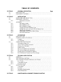
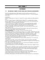
TABLE OF CONTENTS
SECTION 1 GENERAL DESCRIPTION Page
1.1 INTRODUCTION………………………………………………………………..
1.2 EQUIPMENT FEATURES……………………………………………………..
SECTION 2 INSTALLATION
2.1 UNPACKING AND INSPECTION……………………………………………..
2.2 EQUIPMENT SUPPLIED…………………………………………………….…
2.2.1 Optional Accessories…………………………………………………..
2.3 ASSEMBLY…………………….………………………………………………..
2.3.1 AA Battery Holder…….………………………………………………..
2.3.2 NiCad Battery Pack…………………………………………………….
2.3.3 NiCad Battery Charger..……………………………………………….
2.3.4 Charging the NiCad Battery Pack…………………………………….
2.3.5 Getting the most out of your NiCad Battery Pack……….………….
2.3.5 Attaching the Antenna………………………………………………….
2.3.6 Attaching the Belt Clip and Wrist Strap………………………………
2.3.7 RAY106 Dimensions……………………………………………………
SECTION 3 OPERATIONS
3.1 INTRODUCTION………………………………………………………………..
3.2 CONTROLS AND LCD DISPLAY……………………………………………..
3.2.1 Controls………………………………………………………………………
3.2.2 LCD Display…………………………………………………………………
3.3 OPERATING PROCEDURES…………………………………………………
3.3.1 Turning the Power On……..……………………………………………….
3.3.2 The 16 PLUS (priority) channel……………………………………………
3.3.3 Memory Key Functions…..…………………………………………………
3.3.4 Master Reset………………………………………………………………..
3.3.5 All Scan and Memory Scan Modes..……………………………………..
3.3.6 All Seek and Memory Seek Modes..……………………………………..
3.3.7 Monitor Mode (Dual Watch/Tri-Watch)…………………………………..
3.3.8 RAY106 Marine Channels and Their Usage……………………………..
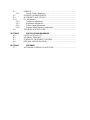
SECTION 4 TECHNICAL DESCRIPTION
4.1 GENERAL……………………………………………………………………….
4.2 THE CONTROL SECTION…………………………………………………….
4.3 THE TRANSMITTER/RECEIVER/PLL SECTIONS…………………………
4.3.1 PLL Circuit…………………………………………………………………..
4.3.2 Transmitter Circuit…………………………………………………………..
4.3.3 Receiver Circuit……………………………………………………………..
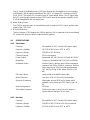
4.4 SPECIFICATIONS………………………………………………………………
4.4.1 Transmitter…………………………………………………………………..
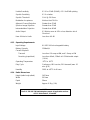
4.4.2 Receiver……………………………………………………………………..
4.4.3 Operating Requirements…………………………………………………..
4.4.4 Radio Dimensions…………………………………………………………..
SECTION 5 MAINTENANCE/ALIGNMENTS/TROUBLESHOOTING

5.1 GENERAL………………………………………………………………………..
5.1.1 How to Contact Raytheon………………………………………………….
5.2 PREVENTIVE MAINTENANCE……………………………………………….
5.3 ALIGNMENTS AND SERVICE………………………………………………..
5.3.1 PLL Adjustment…………………………………………………………………
5.3.2 Frequency Adjustment……………………………………………………..
5.3.3 Modulation Adjustment…………………………………………………….
5.3.4 Power Output Adjustment………………………………………………….
5.3.5 Weather Alert Frequency Adjustment…………………………………….
5.4 TROUBLESHOOTING GUIDE……………………………………………..…
SECTION 6 PARTS LIST AND DRAWINGS
6.1 PARTS LOCATION LIST………………………………………………………
6.2 ASSEMBLY DRAWING………………………………………………………..
6.3 SCHEMATIC DIAGRAMS/PC BOARDS……………………………………..
6.4 INTERNAL WIRING DIAGRAM………………………………………………..
SECTION 7 APPENDIX
7.1 VHF MARINE CHANNEL USAGE GUIDE……………………………………

GLOSSARY OF TERMS
VHF…………………………………… Very High Frequency (30 MHz to 300 MHz)
FM.……………………………………. Frequency Modulation.
MODULATION.……………………… To vary a carrier wave.
CARRIER WAVE.…………………....A radio frequency on which intelligence is superimposed.
DUAL WATCH.…………………….... Monitors channel 16 while working on another channel.
USA CHANNELS.……………….... Channel designations as defined by the FCC.
INTERNATIONAL CHANNELS….… Channel designations as defined by the International
Telecommunication Union.
CANADIAN CHANNELS.……………Channel designations as defined by the Canadian Govt.
WEATHER CHANNELS.………….… Channels for routine and emergency weather
information broadcast by NOAA.
SIMPLEX.……………………………..Transmit and receive on the same frequency.
DUPLEX.…………………………….. Transmit and receive on different frequencies.
SQUELCH.…………………………... To suppress totally.
LCD.………………………………….. Liquid Crystal Display.
TX.……………………………………..Transmit.
RX.……………………………………. Receive.
RF.……………………………………. Radio Frequency.
CPU.………………………………….. Control Processor Unit.
PLL.…………………………………… Phase Locked Loop (A type of Frequency Synthesizer).
VCO.…………………………………. Voltage Controlled Oscillator.
PTT.………………………………….. Microphone Push-To-Talk switch.

SECTION 1
GENERAL DESCRIPTION
1.1 INTRODUCTION
Congratulations on your purchase of Raytheon's RAY106 handheld marine radiotelephone.
The RAY106 is a CPU-controlled, digitally synthesized, compact handheld transceiver, that
provides reliable simplex and duplex (two-frequency) communications between ships at sea
and from ships at sea to public or private shore stations. The RAY106 provides two-way
communications on all U.S., International, and Canadian channel Marine band frequencies,
plus reception on 10 separate weather channels.
This manual describes the physical and functional characteristics of the radiotelephone.
1.2 EQUIPMENT FEATURES
The RAY106 is designed and manufactured to provide ease of operation with excellent
reliability. Some important built-in features of this radio are listed below:
• Totally submersible industrial design.
• All solid-state circuitry for low current drain (longer battery life) and maximum reliability.
• High-performance receiver section with optimum selectivity.
• Access to all available U.S., International, and Canadian VHF Marine band channels.
• Exclusive circuit that automatically selects 16 PLUS (priority) channel when the radio
is turned on.
• Exclusive weather alert feature (when in Monitor Mode).
• Memory channels can be programmed for Memory Scan and Memory Seek operations.
• Selected channel number is always shown on the digital LCD display.
• Aluminum die cast housing to prevent interference of offending RF.
• "Quick" 16 PLUS, for instant selection of the emergency calling channel CH16, or an
alternate priority channel.
• Easy direct mode access to 10 weather channels WX 0 through WX 9.

SECTION 2
INSTALLATION
2.1 UNPACKING AND INSPECTION
Use care when unpacking your new RAY106 from the shipping carton to prevent damage to
the contents. It is also good practice to save the carton and the interior packing material. The
original packing material should be used in the unlikely event it becomes necessary to return
the unit for service.
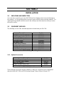
2.2 EQUIPMENT SUPPLIED
The following is a list of the standard equipment included with your RAY106.
Description Part No.
RAY106 Radiotelephone M56800
Wall Charger Adapter110VAC G624700-2
1200mAh NiCad Battery Pack G264696-3
Desktop/Wall Charger G624696-4
Instruction Manual G264696-5
AA Battery Holder G624700-5
Rubber Helical Antenna G624696-6
Leatherette Carrying Case G624696-7
Belt Clip w/Screws G624700-8
Wrist Strap G624700-9
NiCad Battery Safety Message G263695-1
Table 2-1 Equipment Supplied
2.2.1 Optional Accessories
Description Part No.
Universal Drop-In Charger (12VDC, 110VAC, 220 VAC) M56791C
12V Cigarette Lighter Adapter M99-134
High Gain Antenna M56809
Leather Holster/Carrying Case M56810
Soft Carrying Case M56811
Table 2-2 Optional Accessories
These optional accessories may be ordered by calling our Customer Service Department
directly at (603) 647-7530 ext.2333 Monday through Friday 8:30 am-5:00 pm E.S.T.

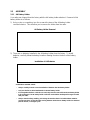
2.3 ASSEMBLY
2.3.1 AA Battery Holder
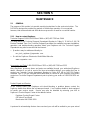
Your radio was shipped from the factory with the AA battery holder attached. Removal of this
battery holder is as follows:
1) Using a coin or screwdriver, turn the screw at the base of the AA battery holder
counterclockwise. This will allow you to remove the holder from the radio.
AA Battery Holder Removal
2) There are no batteries installed in the AA battery holder from the factory. To install
batteries, carefully follow the battery insertion drawing found on the door of the battery
holder.
Installation of AA Batteries
AA BATTERY HOLDER USAGE
• Always carefully note the correct installation of batteries into the battery holder.
• Only use Alkaline or NiCad AA batteries in the AA battery holder.
• If rechargeable alkalines or NiCads are used, they must be removed from the AA battery holder
to be recharged. The AA battery holder cannot be used with the desktop/wall charger included
with your radio.
• Always note the safety, handling, and storage instructions that is included with AA batteries
you may purchase. Especially when storing batteries inside the AA battery holder for extended
periods of time, or emergency use.

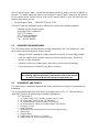
2.3.2 NiCad Battery Pack
Although some voltage may be measured on the NiCad battery pack initially, it must be fully
charged before normal use. Remove the battery pack from the poly bag, and attach it to the
radio housing. Using a coin or screwdriver, turn the screw at the base of the NiCad battery
pack clockwise to secure the battery to the radio housing.
Installing the NiCad Battery Pack
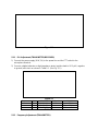
2.3.3 NiCad Battery Charger
The NiCad battery charger can be used as a desktop charger, or can be wall mounted in a
convenient location. To attach the battery charger to a wall or other vertical surface:
1) Remove the two screws from the base of the charger.
2) Remove the wall mounting plate, and attach it to the wall using the screws provided.
3) Reassemble the charger by sliding the charger body down into the wall mounting plate.
4) Replace the two screws in to the base of the wall mounted charger.
Wall Mounting the NiCad Battery Charger

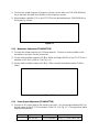
2.3.4 Charging the NiCad Battery Pack
Although some voltage may be measured on the NiCad battery pack initially, it must be fully
charged before normal use.
1) Insert the radio with the battery pack attached into the battery charger.
2) Connect the AC wall adapter into a standard 110VAC wall outlet, and insert the molded
plug into the connector on the side of the NiCad battery charger. The “CHARGE” indicator
on the front of the charger will illuminate when the it is receiving voltage from the AC
adapter.
3) A typical time to recharge the battery pack can be up to 15 hours. Normal operating time
will be an average of 6 to 8 hours on a fully charged battery. To conserve battery life, use
the low (1W) power setting when using the radio for primarily short range communications.
Charging the NiCad Battery Pack
2.3.5 Getting the most out of your Nicad Battery Pack
To extend the life of your NiCad Battery Pack and maintain its best performance during
the use of your radio, follow the guidelines listed below.
• To recharge the radio's battery pack safely, always use only the AC adapter that comes with
your radio or an equivalent replacement.
• The radio should always be turned OFF while recharging the battery pack.
• Avoid short charging cycles. In general, the battery should only be recharged when fully
discharged. The optional Universal Drop-In Charger (M56791C) features a discharge key and a
rapid recharge for fully automatic discharge/recharge battery cycles.
• Avoid high ambient temperatures (over 110
o
F) while recharging the battery pack.
• When the battery pack becomes warm to the touch, it is fully charged and should be removed
from the charger.
• If the radio is to be stored for an extended period of time, remove the battery pack to avoid
possible damage and/or resultant battery failure.

• When it is determined that the battery is no longer useful, it should be disposed of properly.

2.3.6 Attaching the Antenna
Securely fasten the rubber helical antenna to the SMA type connector on the top of the radio.
Attaching the Antenna
2.3.7 Attaching the Belt Clip and Wrist Strap
1) Put the radio into the supplied leatherette carrying case if desired.
2) Remove the belt clip and hardware from the packing materials. Using the two screws
provided attach the belt clip to the rear housing of the radio.
3) Attach the wrist strap by looping it through the mounting hole.
Belt Clip and Wrist Strap Installation

2.3.8 RAY106 Dimensions
Fig. 2-1 OUTLINE DIMENSIONS

SECTION 3
OPERATIONS
3.1 INTRODUCTION
Your RAY106 has the capability to transmit on all legally available Marine VHF radiotelephone
channels. There are channels that are FCC approved but may only be used by authorized
stations for specific purposes, depending on the type of vessel (commercial or non-
commercial). Carefully review section 3.3.8 which lists all of the marine VHF channels
available in your RAY106 for U.S., International, and Canadian radiotelephone use. Full
familiarization with this table is essential when selecting your channels. The U.S. channels are
those channels authorized for use in the U.S. by the FCC. The international frequencies were
agreed upon by the attending countries at the 1968 International Telecommunication Union
meeting in Geneva and are in active use around the world.
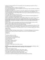
3.2 CONTROLS AND LCD DISPLAY
Refer to Figure 3-1 for familiarization with the controls and display modes.
3.2.1 Controls
1) VOLUME Control (On/Off)
Turns the radio On and controls the Volume of the audio output from the speaker.
2) SQUELCH Control
Allows the user to “quiet” the receiver when no signals are being received.
3) PTT (Push-To-Talk) Switch
When pressed puts the radio into the transmit mode, and "TX" is displayed on the LCD.
4) LIGHT Key (LCD backIight and Keypad Lock functions)
• Backlight - When pressed turns on the backlighting of the LCD display for five seconds.
When the backlight is on, any other keypress will extend the backlight for an additional
five seconds.
• Key Lock - Press and hold the LIGHT key for 3. Seconds. An audible beep will be
heard and an “L” will be displayed in the small channel indicator section of the LCD, to
confirm the key lock mode. In this mode, only the channel number and battery level
indicator is displayed, and all keys are disabled except the PTT and LIGHT keys.
• To exit the Key Lock mode, press and hold the LIGHT key for 3 seconds. A beep will
be heard when the key lock mode is canceled. The Key Lock mode is automatically
disabled when the unit is turned off.

5) SCAN / SEEK Key
• When pressed, puts the radio into the All scan or Memory scan mode. In this mode,
the radio scans through the channels, stopping when radio traffic is detected, then
resumes scanning after the traffic ceases. If the scanning has stopped on a particular
channel, and you wish to continue, press the SCAN key again to continue scanning.
• When pressed and held for 1 second, a beep will be heard and the All seek or Memory
seek mode is activated. In this mode, the radio will stop on channels on which radio
traffic is detected, monitor the traffic for about 7 seconds, then continue to the next
channel with traffic.
6) MEM Key
This key is used to program channels into memory, or to clear channels from memory. The
radio will beep to confirm when channels are being stored into memory.
7) WX / INT Key
• When pressed, selects the Weather mode. “WX” is displayed on the LCD along with a
weather channel number (0 - 9). Use the 5/6 channel keys to select your local NOAA
weather channel. In the WX mode, the transmitter is disabled.
• Press and hold for 1 second, to change from U.S. mode to INT (international) or CA
(Canada) mode. The U.S. mode is the default operating mode.
8) MON / TX Key
• When pressed, selects the Monitor (Dual Watch) mode and “MON” appears on the
LCD. In this mode, the radio will monitor the currently selected working channel and
the priority channel (16plus).
• While in the Monitor (Dual Watch) mode, press the MEM key to activate the Tri-Watch
mode. In the Tri-Watch mode, the last used weather channel is also monitored for
severe weather alert broadcasts.
• When pressed, and held for 1 second, a beep will be heard and the transmit output
power setting alternately changes between 5, 3, and 1 Watt.
9) 16PLUS Key
This key is used to instantly select the priority channel (16plus). CH16 is the default priority
channel from the factory. However an alternate channel can be programmed as the priority
channel if desired.
10)5/6 Channel Keys
The up and down arrow keys are used to change the currently selected channel. The
channel number is increased or decreased once with each keypress or if held, will
continue scrolling through the channels until released.
IMPORTANT NOTE
The INT and CA modes are not legal for use while operating in US waters.

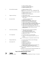
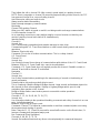
3.2.2 LCD Display
A number of indicators appear on the LCD display in different locations. The following list
describes each indicator and when it will appear.
Fig. 3-2 LCD DISPLAY
À MEM (Memory) : will be displayed when the current channel is a memory channel, and in
Memory Scan/Seek mode.
Á SCAN (All Scan/Memory Scan) : will be displayed when the radio is in the All Scan or
Memory Scan mode.
 MON (Monitor) : will be displayed when the radio is in the Monitor mode.
à WX (Weather) : will be displayed when a weather channel is selected. The “WX” indicator
will blink when a severe weather alert tone is received (in Monitor mode).
Ä SEEK (All Seek/Memory Seek) : will be displayed when the radio is in the All Seek or
Memory Seek mode.
Å INT (International) : will be displayed when International channels are programmed for use.
Æ 5 / 3 / 1 : will be displayed to indicate the current TX power setting.
Ç TX (Transmit) : will be displayed on the LCD when the Push-To-Talk (PTT) switch on the
radio is engaged and the transmitter circuits are providing RF signals to the antenna.
È BATT : is always shown on the display along with the battery voltage bar indicators to
provide a battery level status. The “BATT” indicator will blink when the battery voltage is
low, and the battery needs charging. If a low battery condition is detected during
transmission, “LO” will be shown and the radio will stop transmitting. The battery level is
shown on the LCD as follows:
Battery condition LCD Indicator
Fully charged BATT — — —
Normal operation BATT — —
Needs charging BATT —
É LARGE CHANNEL # : displays the channel number currently in use.
SMALL CHANNEL # : displays the channel number of the priority channel in Monitor mode.
Other indicators shown in the Small Channel segment area:
L : indicates Key Lock mode.
C : indicates Canada mode.
P : indicates Priority mode.

3.3 OPERATING PROCEDURES
Specific operating procedures for the 106 are presented in this section. General information
regarding correct marine channel usage may be found in the Appendix section. Refer to the
Control section 3.2.1 beginning on page 9 for a thorough description of all 106 functions.
3.3.1 Turning the Power On
1) Rotate the ON/OFF/Volume control clockwise to turn the radio on. Continue rotating the
knob clockwise and set it at approximately the midpoint of it's range.
2) Rotate the SQUELCH control fully counterclockwise. (Background noise will be heard.)
3) Set the VOLUME control to the desired listening level.
4) Rotate the SQUELCH control slowly clockwise until the background noise in the speaker
ceases.
5) When the power is initially turned on, the priority channel (16plus) will be selected. Press
the 5/6 channel keys to select the desired working channel. Refer to section 3.3.8 on
pages _ _ - _ _ for the available VHF Marine channels and their frequencies.
To Select A Weather Channel
1) Press the WX key, then the 5/6 channel keys to select your local NOAA weather channel
(0 to 9). When the WX mode is selected, the transmitter is inhibited.
To Transmit
1) To select or change the transmitter output power, press and hold the TX key for 1 second.
There are three output power settings; 5 Watts, 3 Watts, and 1 Watt. The appropriate
power setting depends on the distance the message is to be transmitted, transmitting
conditions, and desired battery life.
2) Press the Push-To Talk (PTT) switch and speak into the microphone using a clear normal
voice.
NOTES:
• Initial communication contacts are usually made over channel 16 as all ships and shore
stations monitor this channel, then a shift to a working channel will be necessary.
• In certain US harbors and on certain channels, the FCC requires the power to be limited to 1
watt. On these "required" channels, the radio automatically selects the 1 watt power output
setting when the channel is selected.
• The RAY106 is designed to meet the new FCC Rules Part 80.203, which states, if the Push-To
Talk (PTT) switch is pressed for over five minutes continuously, the transmitter will disengage.
If this occurs, audible beeps will sound continuously until the PTT switch is released. Upon
release of the PTT switch, normal radio operation will resume.

3.3.2 The 16PLUS (priority) Channel
The 16plus priority channel has been preset to CH16 prior to shipment from the factory.
However, an alternate working channel can be selected as the priority channel if desired, using
the procedure below.
1) Press the 5/6 channel keys to select the desired channel.
2) Press and hold the 16plus key for three seconds. An audible beep tone will confirm that the
selected channel is stored in memory as the new priority channel.
3) To reprogram CH16 as the 16plus channel, repeat steps 1 and 2 for CH16. WX channels
cannot be programmed as the priority channel.
3.3.3 Memory Key Functions
The MEM key is used to program channels into memory for Memory Scan and Memory seek
functions, and for the Memory Recall function.
• To program a channel into memory, select the channel to be stored using the 5/6
channel keys. Press and hold the MEM key for about 2 seconds. The MEM indicator will
appear on the display, and a beep tone will confirm that the channel has been stored to
memory. There is no limit to how many channels can be stored to memory.
• To clear a channel from memory, select the channel to be cleared using the 5/6
channel keys. Press and hold the MEM key for about 1 second. The MEM indicator will no
longer be shown on the display and a beep tone will confirm that the channel has been
erased from memory.
• To review the memorized channels (Memory Recall), press the MEM key twice. The
channels that have been stored into memory will be displayed in sequence on the LCD for
review.
3.3.4 Memory Reset
To clear all channels from memory, and reset the 16plus key to it’s factory default channel
(CH16), hold the MEM key down while turning the radio ON.
3.3.5 All Scan and Memory Scan Modes
1) All Scan
Press the SCAN/SEEK key, to activate the All Scan mode. The SCAN indicator will appear
on the display and the RAY106 will sequentially scan all of the channels in the selected
frequency mode (U.S., INT, or Canada).
• If a signal is received, the scanning will stop until the station clears. After 5 seconds,
scanning will resume. If the scanning has stopped on a received signal, press the
SCAN key again to continue. To cancel the SCAN mode, press the SCAN key.
• If the scanning has stopped on a channel with traffic, and you wish to communicate
with the other party, press the PTT switch to cancel the SCAN mode and remain on
that channel.

2) Memory Scan
• To scan only the channels that have been stored to memory, press the MEM key and
then press the SCAN key while "MEM" is blinking (within 2 seconds).
3.3.6 All Seek and Memory Seek Modes
1) All Seek
Press and hold the SCAN/SEEK key for 1 second, to activate the All Seek mode. The
SEEK indicator will appear on the display and the RAY106 will seek through all of the
channels in the selected frequency mode, stopping for 7 seconds on any channel with
traffic.
• If a signal is received, the seek function will stop temporarily, but will resume after 7
seconds regardless of whether or not the station has cleared. To cancel the SEEK
mode, press the SEEK key.
• If the SEEK mode has found a channel with traffic, and you wish to communicate with
the other party, press the PTT switch to cancel the SEEK mode and remain on that
channel.
2) Memory Seek
• To seek only the channels that have been stored to memory, press the MEM key and
then press the SEEK key while "MEM" is blinking (within 2 seconds).
3.3.7 Monitor Mode
The monitor mode consists of the Dual Watch and Tri-Watch functions.
1) Dual Watch Mode
To start the Dual Watch mode, select the desired working channel and press the MON key.
The MON indicator will appear on the display, and the working channel and the 16plus
(priority) channel will be monitored. In the Dual Watch mode, the current channel being
monitored will be shown in the large LCD channel segments, and the channel in standby
mode will be shown in the small LCD channel segments.
2) Tri-Watch mode
To start the Tri-Watch mode, you must first be in the Dual Watch mode, then press the
MEM key. In addition to the two channels already being monitored, the last used WX
channel will also be monitored for severe weather alert broadcasts.
• If a weather alert broadcast is detected, the RAY106 will emit an alarm and the WX
indicator will begin to blink. The Tri-Watch mode will then be canceled and the radio
will switch to the WX channel to monitor the severe weather broadcast.

3.3.8 RAY106 Marine Channels and Their Usage
• Caution : Operation on channels not designated for use by your classification of craft, or in
International or Canadian frequency mode while operating in US territorial waters is a violation
of FCC Rules and Regulations and may result in severe penalties.
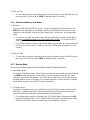
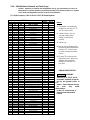
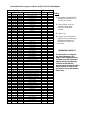
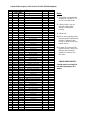
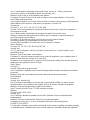
USA Mode Frequency Table for the RAY106 VHF Radiotelephone
Notes:
1 : Transmitter is automatically
disabled on channels 15, 75,
and 76 in USA mode.
2 : 1 Watt initially. User can
override to high power
setting via front panel
controls.
3 : 1 Watt only.
4 : Not for use by general public.
Requires special authorization
from the U.S. Coast Guard,
or under private land mobile
license.
5 : Channel 70 is now used for
Digital Selective Calling only,
therefore transmission is
disabled on channel 70 in
this radio.
**IMPORTANT NOTICE**
*SHADING
Channels 3, 21, 23, 61, 64, 81,
82, and 83, (shaded) are not for
use by the general public in
U.S.
waters. These frequencies may
be used only under
authorization
by the U.S. Coast Guard, or
under private land mobile
license.
USA Mode
Function
Freq. (MHz)
Ship to Ship To
CH
TX
RX
Type of Traffic
Ship Shore
01 156.050 156.050 VTS, Port Operations
üü
03
4
156.150 156.150 Port Operations
üü
05 156.250 156.250 Port Operations
üü
06 156.300 156.300 Intership Safety
üü
07 156.350 156.350 Commercial
üü
08 156.400 156.400 Commercial
üü
09 156.450 156.450 Calling
üü
10 156.500 156.500 Commercial
üü
11 156.550 156.550 Commercial
üü
12 156.600 156.600 Port Operations
üü
13
2
156.650 156.650 Navigation, Bridge to Bridge
üü
14 156.700 156.700 Port Operations
üü
15
1
-
156.750 Environmental
- -
16 156.800 156.800 Emergency, Calling
üü
17
3
156.850 156.850 State Controlled
üü
18 156.900 156.900 Commercial
üü
19 156.950 156.950 Commercial
üü
20 157.000 157.000 Port Operations
üü
21
4
157.050 157.050 Coast Guard
üü
22
4
157.100 157.100 Coast Guard
üü
23
4
157.150 157.150 Coast Guard
üü
24 157.200 161.800 Marine Operator
üü
25 157.250 161.850 Marine Operator
üü
26 157.300 161.900 Marine Operator
üü
27 157.350 161.950 Marine Operator
üü
28 157.400 162.000 Marine Operator
üü
61
4
156.075 156.075 Canadian Coast Guard
üü
63 156.175 156.175 Canadian Coast Guard
üü
64
4
156.225 156.225 Canadian Coast Guard
üü
65 156.275 156.275 Port Operations
üü
66 156.325 156.325 Port Operations
üü
67
2
156.375 156.375 Commercial
üü
68 156.425 156.425 Boat Operations, Recreational
üü
69 156.475 156.475 Boat Operations, Recreational
üü
70
5
-
156.525 Digital Selective Calling
- -
71 156.575 156.575 Boat Operations, Recreational
üü
72 156.625 156.625 Boat Operations, Recreational
üü
73 156.675 156.675 Port Operations
üü
74 156.725 156.725 Port Operations
üü
75
1
-
156.775 CH16 Guard Band
- -
76
1
-
156.825 CH16 Guard Band
- -
77
3
156.875 156.875 Port Operations
üü
78 156.925 156.925 Boat Operations, Recreational
üü
79 156.975 156.975 Commercial
üü
80 157.025 157.025 Commercial
üü
81 157.075 157.075 Coast Guard
üü
82 157.125 157.125 Coast Guard
üü
83 157.175 157.175 Coast Guard
üü
84 157.225 161.825 Marine Operator
üü
85 157.275 161.875 Marine Operator
üü
86 157.325 161.925 Marine Operator
üü
87 157.375 161.975
4
Marine Operator
üü
88 157.425 157.425 Commercial
üü
La pagina si sta caricando...
La pagina si sta caricando...
La pagina si sta caricando...
La pagina si sta caricando...
La pagina si sta caricando...
La pagina si sta caricando...
La pagina si sta caricando...
La pagina si sta caricando...
La pagina si sta caricando...
La pagina si sta caricando...
La pagina si sta caricando...
La pagina si sta caricando...
La pagina si sta caricando...
La pagina si sta caricando...
La pagina si sta caricando...
La pagina si sta caricando...
La pagina si sta caricando...
La pagina si sta caricando...
La pagina si sta caricando...
La pagina si sta caricando...
La pagina si sta caricando...
La pagina si sta caricando...
La pagina si sta caricando...
La pagina si sta caricando...
La pagina si sta caricando...
La pagina si sta caricando...
La pagina si sta caricando...
-
 1
1
-
 2
2
-
 3
3
-
 4
4
-
 5
5
-
 6
6
-
 7
7
-
 8
8
-
 9
9
-
 10
10
-
 11
11
-
 12
12
-
 13
13
-
 14
14
-
 15
15
-
 16
16
-
 17
17
-
 18
18
-
 19
19
-
 20
20
-
 21
21
-
 22
22
-
 23
23
-
 24
24
-
 25
25
-
 26
26
-
 27
27
-
 28
28
-
 29
29
-
 30
30
-
 31
31
-
 32
32
-
 33
33
-
 34
34
-
 35
35
-
 36
36
-
 37
37
-
 38
38
-
 39
39
-
 40
40
-
 41
41
-
 42
42
-
 43
43
-
 44
44
-
 45
45
-
 46
46
-
 47
47


Raymarine Ray 106 Manuale utente
- Categoria
- Radio
- Tipo
- Manuale utente
in altre lingue
- English: Raymarine Ray 106 User manual
Documenti correlati
Altri documenti
-
Standard Horizon C866S VHF Manuale del proprietario
-
Uniden MHS75 Guida utente
-
Furuno FM4850 Manuale utente
-
-
ICOM IC-M127EURO Manuale del proprietario
-
Cobra MR HH150 FLT Manuale del proprietario
-
Kenwood TH-F6A Manuale utente
-
-
-
INTEK seatec-5 Manuale del proprietario