CARLO GAVAZZI EM24DINAV53LM1X Guida d'installazione
- Tipo
- Guida d'installazione

n
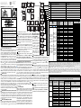
JOYSTICK AND KNOB FUNCTIONS
Refer to fig.1. In the measurement mode: 1) push for at
least 3 seconds to enter programming; 2-3) to scroll the
measurement pages according to tab. 3; 4-5) to display and
scroll the information pages relevant to the programmed
parameters and instrument firmware release (see TAB 5). In
the programming mode: 1) to access to the menu or enter
the modified value; 2-3) to scroll the menus or
increase/decrease the values to be modified; 4-5) to scroll the
menus or increase/decrease the values to be modified. The
knob (see fig.2) prevents from accessing the programming
mode when in position. It allows the direct access to a
selected page (among the available ones, depending on the
“APPLiCAt” parameter, see tab.3) when in “1”, “2” and
positions. The frontal red LED (fig.2) flashes proportionally
to the active imported energy consumption if the selector is in
" - 1 - 2" position, and to the reactive inductive energy con-
sumption in "kvarh" position. Any kind of negative (exported)
energy and power will not be managed by the front LED.
n
DISPLAY LAYOUT
The display is divided into 3 lines (as illustrated by the dotted
lines in the TAB 1 table). The engineering units are referred
to the variable shown in the relevant line. The “negative”
symbols (∑, dmd) refer to all the displayed variables. To
improve the display legibility, the EM24 uses some symbols
(see TAB 1). In case of "OVERFLOW", the instrument dis-
plays "EEEE": at the same time the DMD calculation, the
hour-counter and the energy meters functions are inhibited
and the alarm outputs are activated. The indication "EEEE" in
a single phase variable automatically implies the overflow
condition of the relevant system variable, and the PF indica-
tion is forced to "0.000".
n
MEASUREMENT PAGES AND INFORMATION PAGES
To display and scroll the measurement pages the joystick is
to be moved to direction 2 or 3 (see fig.1). According to the
selected “APPLiCAt” parameter (see tab.2), different meas-
urement pages are available (see tab.3). To display and scroll
the information pages the joystick is to be moved to direction
4 or 5 (see fig.1).
n
BASIC PROGRAMMING AND RESET
To enter the complete programming mode the joystick is to be
pressed in direction 1 for at least 3 sec. (see fig.1): the knob
(see fig.2) must NOT to be in (with the knob in this posi-
ENGLISH
Fig. 1
F
ig. 2
L
ED
TAB 1
ENG- Displaying of water cubic meters
ITA- Visualizzazione contatore metri cubi acqua
ENG- Displaying of gas cubic meters
ITA- Visualizzazione contatore metri cubi gas
ENG- Displaying of phase-to-neutral system voltage
ITA- Visualizzazione tensione fase-neutro di sistema
ENG- Displaying of phase-to-phase system voltage
ITA- Visualizzazione tensione fase-fase di sistema
ENG- Displaying of max values
ITA- Visualizzazione valori massimi
ENG- User ID
ITA- Identificatore Utente
1
2
3
CARLO GAVAZZI
A u t o m a t i o n C o m p o n e n t s
Carlo Gavazzi Controls SpA,
V
ia Safforze, 8 - 32100
Belluno (Italy)
Tel. +39 0437 355811,
F
ax +39 0437 355880
E
M24DIN USE IMENG ITA 8021487 270515
EM24 DIN „
Compact 3-phase Energy Analyzer‰
T
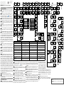
AB. 3
N
o
Line 1
Riga 1
Line 2
Riga 2
Line 3
Riga 3
APPLiCAt
A b C d E F G H
1 2
1
P
hase seq.
V
LN sys
H
z
x x x x x x x
2
Phase seq. VLL sys Hz
x x x
ENG- Selector
position which
can be linked to
any of the vari-
able conbina-
tions listed
above (No. from
1 to 31).
ITA- Posizione
del selettore
associabile ad
ogni combina-
zione di variabili
elencate sopra
(No. da 1 a 31)
ENG- In this
position the
front LED
blinks pro-
portionally to
the reactive
e n e r g y
(kvarh) being
mesured.
ITA- In
q u e s t a
posizione il
LEDfrontale
l a m p e g g i a
proporzional-
mente all’e-
nergia reatti-
va (kvarh)
misurata
3
Tot kWh (+) W sys dmd W sys dmd max
x x x x x x x
4
kWh A dmd max (5) PArt
x x x
5
T
ot kvarh (+)
V
A sys dmd
V
A sys dmd max
x x x x
6
k
varh
V
A sys
P
Art
x x x
7
(1) Totalizer 1 (2) (3) (3)
x x x x
8
(1) Totalizer 2 (2) (3) (3)
x x x x
9
(1) Totalizer 3 (2) (3) (3)
x x x x
10
(1) kWh (+) t1 (4) W sys dmd
x x x x
11
(1) kWh (+) t2 (4) W sys dmd
x x x x
12
(1) kWh (+) t3 (4) W sys dmd
x x x x
1
3
(
1)
k
Wh (+)
t
4 (4)
W
sys dmd
x x x x
1
4
(
1)
k
varh (+)
t
1 (4)
W
sys dmd
x x x x
1
5
(
1)
k
varh (+)
t
2 (4)
W
sys dmd
x x x x
16
(1) kvarh (+) t3 (4) W sys dmd
x x x x
17
(1) kvarh (+) t4 (4) W sys dmd
x x x x
18
(1) kWh (+) X W X User X
x
1
9
(
1)
k
Wh (+) Y
W
Y
U
ser Y
x
20
(1) kWh (+) Z W Z User Z
x
21
Total kvarh (-) VA sys dmd VA sys dmd max
x x
22
Total kWh (-) W sys dmd W sys dmd max
x x x
23
Hours W sys PF sys
x x x x
24
Hours var sys PF sys
x x x x
25
var L1 var L2 var L3
x x
26
VA L1 VAL2 VAL3
x x
27
PF L1 PF L2 PF L3
x x
28
W L1 W L2 W L3
x x x
29
A L1 A L2 A L3
x x x x
30
V L1-2 V L2-3 V L3-1
x x x
31
V L1 V L2 V L3
x x x x x
ENGLISH- (1) The page is available according to the enabled functions (see pos. 04 or pos. 10 in the flowchart). (2) m
3
Gas, m
3
Water, kWh remote heating or external
energy counter. (3) Hot or Cold (water) or “out ENE” (external energy counter). (4) The active tariff is displayed with an “A” before the “t1-t2-t3-t4” symbols. Note: in case
of alarm all the indications blink. When moving the joystick in any directions, the blinking will stop and will start again after the joystick has not been moved for 60 sec.,
and only if the alarm is still active. During the programming phase there’s a time out of 120 sec. expired which the instrument goes back to the previously selected mea-
suring page. (5) Highest dmd current among the three phases. There is a time out of 60sec that brings the scrolled page to the default one.
ITALIANO- (1) La pagina è disponibile a seconda della funzione abilitata (vedere pos. 04 o pos. 10 nel diagramma di flusso). (2) m
3
Gas, m
3
Acqua, kWh teleriscalda-
mento o contatore esterno di energia. (3) Hot (acqua calda) o Cold (acqua Fredda) o “out ENE” (contatore esterno di energia). (4) La tariffa attiva è visualizzata con una
“A” prima dei simboli “t1-t2-t3-t4”. Note: in caso di allarme tutte le indicazioni lampeggiano. Agendo sul joystick in qualsiasi direzione il lampeggio si interrompe per poi
riprendere dopo 60sec. di inattività se la condizione di allarme persiste. In fase di programmazione c’è un tempo di time out di 120 sec., scaduto il quale lo strumento si
riporta alla pagina di misura preselezionata. (5) Massima corrente dmd tra le tre fasi. C’è un tempo di time-out di 60sec. scaduto il quale lo strumento passa dalla pagina
visualizzata in quel momento alla pagina definita dal menù “selector”.
TAB. 2
ENGLISH Application ITALIANO Applicazione
A
Basic domestic Domestica base ** Domestica base **
b
Shopping centres ** Centri commerciali **
C
Advanced domestic ** Domestica avanzata
d
Multi domestic (camping, marinas) *, ** Multi-domestica (campeggi, porti turistici) *, **
E
Solar energy * Energia solare *
F
Industrial * Industriale *
G
Advanced industrial ** Industriale avanzata**
H
Advanced industrial for power generation * Industriale avanzata per cogenerazione *
TAB. 4
ENG- In applications A, b, C, d and G the flow direction of the current into the instrument does not affect the measurements.
ITA- Nelle applicazioni A, b, C, d, G il verso della corrente nello strumento non influisce nella misura.
APPLICATION
APPLICAZIONE
REAL MEASUREMENTS
MISURE REALI
DISPLAYED VALUES
VALORI VISUALIZZATI
ENERGIES ENERGIE ENéRGIA
DISPLAYED ENERGIES
ENERGIE VISUALIZZATE
NOTES
NOTE
A - b - C - d -
G
W, var, L PF W, var kWh, kvarh
W, -var, C PF W, -var kWh, kvarh
ENG- The negative energies are counted
always as positive. ITA- Le energie negative
sono conteggiate sempre come positive
-W, var, C PF W, -var kWh, kvarh
-W, -var, L PF W, var kWh, kvarh
E
W, var, L PF W kWh
W, -var, C PF W kWh
-W, var, C PF -W -kWh
-W, -var, L PF -W -kWh
F
W, var, L PF W, var kWh, kvarh
W, -var, C PF W, -var kWh, -kvarh
-W, var, C PF -W, var -kWh, kvarh
-W, -var, L PF -W, -var -kWh, -kvarh
H
W, var, L PF W, var, L PF kWh, kvarh
W, -var, C PF W, -var, C PF kWh, -kvarh
-W, var, C PF -W, var, C PF -kWh, kvarh
-W, -var, L PF -W, -var, L PF -kWh, -kvarh
tion, the MID parameters cannot be
modified) otherwise the programming mode is not allowed.
: only for A, B, C and E applications and only with the knob
in position and moving the joystick towards direction 1
(see fig. 1), it will be possible to reset the “Wdmd max” and
“VAdmd max” values; the display will show “rESEt no”: set
“YES” and confirm pushing the joystick towards direction 1
(this action may be made only once from the switching on of
the instrument).
PASS?: entering the right password (default value is 0)
allows accessing the main menu. RESET: entering the pass-
word value 1357 allows accessing the “reset” menu. “rESEt
”= peak dmd values reset; “rESEt.dmd”= dmd values reset;
“EnE P.rES”= partial energy meter reset.
CnG PASS: it allows changing the password.
APPLiCAt: it allows selecting the pertinent application
(see tab.2).
NOTE: Application D is not available in MID meters.
NOTE: Negative energy (-kWh) is not MID certified.
The interfaces have not any effect on the measurements.
n
FUNZIONI DEL JOYSTICK E DEL SELETTORE
In modalità di misura: 1) Premere per almeno 3sec. per
accedere alla programmazione; 2-3) scorre le pagine di misu-
ra (Tab 3); 4-5) visualizza e scorre le pagine di informazione
relative ai parametri di programmazione e revisione firmwar-
re (vedi TAB 5). In modalità di programmazione: 1) confer-
ma valore ed entra nei sotto menù; 2-3) scorre i menù ed
incrementa/decrementa i valori alfanumerici; 4-5) scorre i
menù e incrementa/decrementa i valori alfanumerici. Il selet-
tore visibile in figura 2, oltre a bloccare l’ingresso in program-
mazione se posizionata in , permette un accesso diretto
alle pagine di misura pre-selezionate (Tab 3) nelle posizioni
1, 2 e . Le pagine di misura cambiano a seconda della
modalità “APPLiCAt” selezionata. Il LED rosso frontale
(fig.2) lampeggia proporzionalmente al consumo di energia
attiva totale importata se il selettore è in posizione " - 1 - 2"
e al consumo di energia reattiva induttiva se in posizione
"kvarh". Ogni tipo di energia negativa (esportata) non è
gestita dal LED.
n
LETTURA DISPLAY
Il display è suddiviso in tre “fasce” dette righe di lettura (come
illustrato nella immagine in tabella TAB 1 con le linee tratteg-
giate). Le unità di misura si riferiscono ai valori corrisponden-
ti nelle rispettive righe di lettura ad eccezione di quelle scritte
in “negativo” (∑, dmd) che si riferiscono a tutti i valori visua-
lizzati dal display. Al fine di migliorare la chiarezza e l’imme-
diatezza della lettura dello strumento, EM24 utilizza alcuni
simboli grafici (Tab1). In caso di "OVERFLOW" lo strumento
visualizza "EEEE": contemporaneamente le funzioni di calco-
lo DMD, conta-ore e contatori di energia vengono inibite e le
uscite allarme vengono attivate. L’indicazione "EEEE" su una
variabile di singola fase si estende automaticamente alla cor-
rispondente variabile di sistema e l'indicazione PF viene por-
01
ITALIANO
03
02
00
tata a "0.000".
n
PAGINE DI MISURA
E PAGINE INFORMA-
ZIONI STRUMENTO
Per visualizzare e scorre-
re le pagine di misura
agire sul joystick nelle
direzioni 2-3 (fig 1). A
seconda della modalità
“APPLiCAt” preseleziona-
ta (TAB 2) verranno
visualizzate le pagine di
misura della tabella “TAB
3”. Per visualizzare le
pagine informative dello
strumento agire sul joy-
stick nelle direzioni 4-5
(fig. 1).
n
PROGRAMMAZIONE BASE E RESET
Per accedere alla programmazione completa dello strumento
premere il joystick nella direzione 1 per almeno 3sec. (fig 1),
il selettore di figura 2 NON si deve trovare nella posizione di
blocco programmazione indicata con il simbolo (con il
selettore in questa posizione non è possibile modificare i
parametri MID).
: solamente per le applicazioni A, B, C ed E e solamente
con il selettore in posizione premendo il joystick nella dire-
zione 1 (fig. 1), sarà possibile resettare i valori “Wdmd max”
e “VAdmd max”: comparirà sul display l’indicazione “rESEt
no” impostare “YES” e confermare premendo il joystick in
direzione 1 tale opzione può essere fatta solamente una volta
dall’accensione dello strumento.
PASS? : inserendo il valore di password corretto (di
default 0) si accede al menù principale. RESET: inserendo il
valore di password 1357 si accede al menù “reset”. “rESEt
dmd”= reset dei valori dmd massimi; “rESEt.(dmd)”= reset dei
valori dmd; “EnE P.rES”= reset dei contatori di energia parzia-
li.
CnG PASS: nuova password, personalizza la password.
APPLiCAt: seleziona l’applicazione pertinente (vedere
tabella TAB. 2).
NOTA: L'applicazione D non è disponibile negli strumen-
ti MID.
NOTA: L'energia negativa (-kWh) non è certificata MID.
Le interfacce non hanno alcun effetto sulle misure.
03
02
01
00
* Not available with option PF A. ** Not available with option PF B
* Non disponibile con l’opzione PF A. ** Non disponibile con l’opzione PF B

ADVANCED PROGRAMMING
USEr: (APPLiCAt” d only) it links an ID code (from 1 to 9999) to the
user of the displayed consumption (three 1-phase independent users
by instrument).
SELECtor: it allows selecting the measuring page (tab. 3) to be
displayed according to the knob position (see fig.2); SELEC. 1 (2,3,
LoC): it selects the knob position (1, 2, o ); PA.1 (31): it selects
the page number to be displayed (from No. 1 to 31 see TAB 3).
SYS: it allows selecting the electrical system. 3P.n: 3-phase unba-
lanced with neutral; 3P: 3-phase unbalanced without neutral; 3P.1: 3-
phase balanced with or without neutral 2P: 2-phase; 1P: single phase.
Ut rAtio: VT ratio (1.0 to 6000). Example: if the connected VT pri-
mary is 5kV and the secondary is 100V, the VT ratio to be set is 50
(that is 5000/100).
Ct rAtio: CT ratio (1.0 to 60.00k). Example: if the connected CT
primary is 3000A and the secondary is 5A, the CT ratio is 600 (that is:
3000/5).
P int.ti: it is the integration time used to calculate the demanded
powers (Wdmd, VAdmd). The selectable range is between 1 and 30
minutes.
diG in 1 / diG in 2 / diG in 3: (IS option only) it allows defining the
digital inputs function. rEM: for reading the digital input status by
means of serial communication; SYnC: dmd calculation synchronisa-
tion; tAr: multi-tariff management (see also Tab. 6); GAS: gas metering;
Cold: cold water metering; Hot: hot water metering; kWh + Hot: distant
heating (kWh) meters. kWh out: reading of an external energy counter.
PrESCAL.1 (or 2 or 3): it sets the weight of each pulse (from 0.001 to
999.9 m
3
or kWh/pulse). Move the joystick on left or right to move the
decimal point. Note: the digital inputs have to be set with different
modes among them, in case they are used for GAS, CoLd, HoT, kWh+
Hot or kWh out.
FiLtEr.S: it allows selecting the operating range of the digital filter
as % of the full scale values (1 to 100). Only in case of applications F,
G and H.
FiLtEr.Co : it allows selecting the filtering coefficient (from 1 to 32).
The higher the coefficient, the higher is the stability and the updating
time of the measurement. Only in case of applications F, G and H.
AddrESS : it allows selecting the serial address of the instrument
(from 1 to 247). bAudrAtE: it allows selecting the baud rate (4.800 or
9.600 baud).
diG out. 1 / diG out. 2 (“O2” and “R2” models only) it allows selec-
ting the digital outputs function. PuLS/nEG: pulse output selection
(proportional to positive/negative energy respectively). The pulse wei-
ght is to be set from 0.001 to 10.00 (kWh/kvarh per pulse). Only posi-
tive kvarh is retrasmitted. ton: select the duty cycle of the digital output
(30ms or 100ms), according to the used reading device. In case of high
power to retransmit it is advisable to use the lowest time; tESt: activa-
ted on the pulse output when “YES” is selected. In the further menu
program the simulated power value (kW or kvar) is corresponding to a
pulse frequency proportional to it and based on the “PULSEou.1/2”.
The test is active until you exit from this menu. AL: alarm output (this
function is active only in case of application C, E, G and H), selection
of the variable to be controlled (Ph.AL: phase sequence alarm), activa-
tion setpoints “on AL” and deactivation setpoints “off AL”, with “on AL”
≥ “off AL” equal to high alarm, with “on AL” < “off AL” equal to low
alarm. “t.dEL”: delay on activation from 0 to 255 sec. “out1-2”: output
status in normal condition, “nE” if normally energised or “nd” if normal-
ly de-energised, are to be set too).
EnE t.rES: it allows the reset of all the total counters.
End: it allows exiting the programming mode by pressing the joy-
stick in direction 1 (see fig. 1). Joystick directions 4 and 5 allow brow-
sing the main menu again.
PROGRAMMAZIONE AVANZATA
USEr: (solo “APPLiCAt” d) associa un codice identificativo (da 1 a
9999) all’utente del consumo visualizzato (3 utenti monofase indipen-
14
13
12
11
10
09
08
07
0
6
05
04
ENGLISH
15
16
ITALIANO
04
denti per strumento).
SELECtor: seleziona la pagina di misura (TAB 3) da associare alla
posizione del selettore frontale (fig. 2); SELEC. 1 (2, 3, LoC): selezio-
na la posizione del selettore (1, 2, o ); PA.1 (31): seleziona la
pagina da visualizzare (da No. 1 a 31 vedere TAB 3).
SYS : sitema elettrico: 3Pn: trifase sbilanciato con neutro; 3P: tri-
fase sbilanciato senza neutro; 3P1: trifase bilanciato con o senza neu-
tro; 2P: bifase; 1P monofase.
Ut rAtio : rapporto TV (da 1,0 a 6000). Esempio: se il primario del
TV connesso è di 5kV e il secondario è di 100V il rapporto di TV corri-
sponde a 50 (ottenuto eseguendo il calcolo: 5000/100).
Ct rAtio : rapporto TA (da 1,0 a 60,00k). Esempio: se il primario
del TA ha una corrente di 3000A e il secondario di 5A, il rapporto TA
corrisponde a 600 (ottenuto eseguendo il calcolo: 3000/5).
P int.ti : tempo di integrazione per il calcolo della potenza media:
selezionare il tempo desiderato da 1 a 30 minuti.
diG in 1 / diG in 2 / diG in 3 : (solo con opzione “IS”) funzione
ingressi digitali: rEM: remotazione ingressi digitali. SYnC: sincronizza-
zione; tAr: tariffazione (Tab. 6); GAS: contatore gas; Cold: contatore
acqua fredda; Hot: contatore acqua calda; kWh + Hot: teleriscalda-
07
06
05
08
09
10
mento (kWh). kWh out: lettura di un contatore di energia esterno.
PrESCAL.1 (o 2 o 3): impostazione peso impulsi (da 0,001 a 999,9 m
3
o kWh per impulso) spostando a destra o sinistra il joystick si sposta il
punto decimale. Nota: nel caso di utilizzo per GAS, CoLd, Hot, kWh +
Hot o kWh out.
FiLtEr.S : campo di intervento del filtro digitale espresso in % del
valore di fondo scala (da 1 a 100). Solo per applicazioni F, G o H.
FiLtEr.Co : coefficiente di filtraggio da 1 a 32. Aumentando il coef-
ficiente aumenta la stabilità e il tempo di assestamento dei valori visua-
lizzati. Solo per applicazioni F, G e H.
AddrESS: indirizzo seriale: da 1 a 247. bAudrAtE: velocità di tra-
smissione dati (4.800; 9.600 bit/s).
diG out. 1 / diG out. 2 : (solo con opzione “O2” e “R2”) funzione
uscita digitale: PuLS/nEG: come uscita impulsi (proporzionale rispetti-
vamente all’energia positiva/negativa). Il peso dell’impulso deve esse-
re impostato da 0,001 a 10,00 (kWh/kvarh per impulso). Solo i kvarh
sono ritrasmessi. ton: seleziona il duty cycle dell’uscita impulsiva
(30ms o 100ms), per adattare gli impulsi al dispositivo di lettura degli
stessi, in caso di potenze elevate è consigliabile utilizzare il tempo più
basso.
11
12
13
14
tESt: attivo su uscita impulsi con selezione
YES. Nel menù successivo impostare il
valore di potenza (kW o kvar) simulata a cui
corrisponderà una frequenza degli impulsi
ad essa proporzionale in base a
“PULSE.ou 1/2”, la funzione è attiva finché
si rimane nel menù. AL: come allarme (fun-
zione attiva solo per le applicazioni C, E, G
e H), seleziona la variabile da controllare (Ph.AL: allarme sequenza
fase), le soglie “on AL” (attivazione) e “off AL” (disattivazione); con “on
AL” ≥ “off AL” = allarme di massima, con “on AL” < “off AL” = allarme
di minima. “t dEL”: ritardo all’attivazione, da 0 a 255s. “out 1-2”: stato
dell’uscita a riposo “nE” normalmente eccitata o “nd” normalmente
diseccitata.
EnE t.rES: azzeramento di tutti i contatori totali.
End : per tornare al modo misura premere il joystick in direzione 1
(vedere figura 1), o in direzione 4-5 per restare nel menù di program-
mazione.
15
16
TAB. 5
Type / Tipo
1st line / 1
a
linea 2nd line / 2
a
linea 3rd line / 3
a
linea
Meter information - Informazione strumento
Firmware release - Revisione firmware -
Versión del firmware
Year of production- Anno di produzione
Meter information - Informazione strumento Pulse LEd - LEd impulsi
Number of kWh per pulse - Numero di kWh
per impulso
Meter information - Info strumento System (1-2-3-phase) - Sistema (1-2-3-fasi)
Connection (2-3-4-wire)- Connessione (2-3-4-
fili)
dmd (time) - dmd (tempo)
Meter information (AV5-6) - Info strumento
(AV5-6)
CT ratio - Rapporto TA
Meter information (AV5-6) - Info strumento
(AV5-6)
VT/PT ratio - Rapporto TV
In case of alarm output - In caso di uscita
allarme
Alarm output 1 or 2 status- Stato allarme 1 o
2
Set-point value - Valore della soglia Variable type - Variabile allarmata
In case of pulse output - In caso di uscita
impulsi
Pulse output 1 or 2 variable link (kWh/kvarh) -
Variabile associata all’uscita 1 o 2
(kWh/kvarh)
Output pulse weight (kWh-kvarh / pulse) -
Peso dell’impulso (kWh-kvarh / impulso)
Empty (positive energy pulse) nEG (negative
energy pulse) - Vuoto (impulsi energia positi-
va) nEG (impulsi energia negativa)
In case of communication port - Con porta
di comunicazione
Serial port - Porta seriale Address - Indirizzo
RS485 status (RX-TX) - Stato della RS485
(RX-TX)
In case of communication port - Con porta
di comunicazione
Secondary address (for M-bus protocol) -
Indirizzo secondario (per protocollo M-bus)
Sn
The menus availability depends on the “APPLiCAt”
selection.
La presenza dei menù è in funzione della selezione
“APPLiCAt”.
TAB 6
diG in
tAr diG in diG in
1 on on
2 off on
3 on off
4 off off
CARLO GAVAZZI
A
u t o m a t i o n C o m p o n e n t s
C
arlo Gavazzi Controls SpA,
V
ia Safforze, 8 - 32100
Belluno (Italy)
T
el. +39 0437 355811,
F
ax +39 0437 355880
E
M24DIN USE IMENG ITA 8021487 270515
EM24 DIN „Compact 3-phase Energy Analyzer‰
-
 1
1
-
 2
2


CARLO GAVAZZI EM24DINAV53LM1X Guida d'installazione
- Tipo
- Guida d'installazione
in altre lingue
Documenti correlati
-
CARLO GAVAZZI EM2696AV53HI3XXXX Guida d'installazione
-
CARLO GAVAZZI EM24DINAV23XE1PFB Manuale utente
-
-
CARLO GAVAZZI WM14DINAV63BPG Guida d'installazione
-
-
-
-
-
-