
Instruction
047U59378
05/2023
Giacomini S.p.A.
Via per Alzo 39, 28017 San Maurizio d’Opaglio (NO) Italia
+39 0322 923372 - giacomini.com
R586HPI + COMPLETION CODES
3
4
2
1
6
7
5
F
HB GA
D
E
C
(g.1)
VIDEO TUTORIAL
G H I L
X C
M S UT
P Q
ON
B
Y
V
R
FE
A
D
Ø
(g.6)
A B C D E F G H I L M N
440 540 244 190 115 135 138 52 52 64 135 111
O P Q R S T U V Ø X Y
220 157 331 52 80 94 74 588 13 410 510 [mm]
R586HPI
R148HP
R148HP
THERMAL
STORAGE
TANK
HEAT PUMP
HEATING
SYSTEM
HDW STORAGE (g.2a)
R586HPI
R148HP
R148HP
THERMAL
STORAGE
TANK
HEAT PUMP
COOLING
SYSTEM
HDW STORAGE (g.3a)
THERMAL
STORAGE
TANK
HEAT PUMP
HEATING
SYSTEM
R586HPI
R148HP
R148HP
HDW STORAGE (g.2b)
R586HPI
R148HP
R148HP
THERMAL
STORAGE
TANK
HEAT PUMP
HDW STORAGE
COOLING
SYSTEM
(g.3b)
(g.4)
5 mm
CLOSE
CLOSE
CLOSE
CLOSE
OPEN
OPEN
5 mm
CLOSE
CLOSE
CLOSE
CLOSE
1 2 3 4 5
(g.5a)
CLOSE
CLOSE
OPEN
OPEN
OFF
1 2 3 4 5
(g.5b)
Avvertenze pe r la sicur e z za. L’installa z i o ne, la me s s a in ser v i z io e la pe r i o dica manu te n z ione del pr o dot to de vono essere es e g ui te da per sona l e professiona l mente abi li t a t o, in ac cordo co n i regolam e n t i nazional i e/o i re q u isiti locali . L’install a t o re quali c a t o deve ado t tare tutti gli
accorgimenti necessari, incluso l’utilizzo di Dispositivi di Protezione Individuale, per assicurare la propria incolumità e quella di terzi. L’errata installazione può causare danni a persone, animali o cose nei confronti dei quali Giacomini S.p.A. non può essere considerata responsabile.
Smaltimento imballo. Scatole in cartone: raccolta differenziata carta. Sacchetti in plastica e pluriball: raccolta differenziata plastica.
Smaltimento del prodot to. Alla ne del suo ciclo di vita il prodotto non deve essere smaltito come riuto urbano. Può essere portato ad un centro speciale di riciclaggio gestito dall’autorità locale o ad un rivenditore che offre questo ser vizio.
Altre informazioni. Per ulteriori informazioni consultare il sito giacomini.com o contattare il servizio tecnico. Questa comunicazione ha valore indicativo. Giacomini S.p.A. si riserva il diritto di apportare in qualunque momento, senza preavviso, modiche per ragioni
tecniche o commerciali agli articoli contenuti nella presente comunicazione. Le informazioni contenute in questa comunicazione tecnica non esentano l’utilizzatore dal seguire scrupolosamente le normative e le norme di buona tecnica esistenti.
Dati tecnici
Prestazioni
• Fluidi di impiego: acqua, soluzione glicolate (max. 30 % di glicole)
• Campo di temperatura: 5÷90 °C
• Pressione massima di esercizio: 10 bar
• Filtro del defangatore: 300 µm
• Capacità magnetica del defangatore: 13000 Gauss
• Tempo di movimento delle valvole deviatrici: 40 sec. o 8 sec. a seconda delle versioni
Materiali
• Componenti principali: ottone
• Maniglie valvole a sfera: plastica con placchetta rossa o blu
• Filtro del defangatore: acciaio inox AISI 304
• Magnete del defangatore: neodimio (N42H)
• Guarnizioni: EPDM
Perdite di carico
CODICE Kv VALVOLA DEVIATRICE Kv DEFANGATORE
R586HPIY005 11,0 6,7
R586HPIY105 8,0 6,7
R586HPI Modulo idronico per pompa di calore
IT
Versioni e codici
CODICE ATTACCHI VALVOLA DEVIATRICE CODICI DI COMPLETAMENTO
R586HPIY005 G 1”F
Valvola deviatrice
40 secondi
(R279D)
• K270Y101: attuatore 230 V, per valvola deviatrice 40 s
• K270Y102: attuatore 24 V, per valvola deviatrice 40 s
• R540FY002: termometro a contatto, colore rosso, scala 0÷120 °C, Ø 40 mm (da installare sulle maniglie delle valvole a sfera al posto delle placchette colorate)
• R540FY022: termometro a contatto, colore blu, scala 0÷120 °C, Ø 40 mm (da installare sulle maniglie delle valvole a sfera al posto delle placchette colorate)
• R586HPIW005: coibentazione
• P76WHPIY001: kit circolatore Wilo Para 25/7, interasse 130 mm, completo di valvola a sfera e ritegno
• P76WHPIY002: kit circolatore Wilo Para 25/7, interasse 180 mm, completo di valvola a sfera e ritegno
• R197HPIY001: kit con tronchetto per installazione circolatore, interasse 130 mm, completo di valvola a sfera e ritegno
• R197HPIY002: kit con tronchetto per installazione circolatore, interasse 180 mm, completo di valvola a sfera e ritegno
R586HPIY105 G 1”F Valvola deviatrice
8 secondi
• K270Y211: attuatore 230 V, per valvola deviatrice 8 s
• R540FY002: termometro a contatto, colore rosso, scala 0÷120 °C, Ø 40 mm (da installare sulle maniglie delle valvole a sfera al posto delle placchette colorate)
• R540FY022: termometro a contatto, colore blu, scala 0÷120 °C, Ø 40 mm (da installare sulle maniglie delle valvole a sfera al posto delle placchette colorate)
• R586HPIW105: coibentazione
• P76WHPIY001: kit circolatore Wilo Para 25/7, interasse 130 mm, completo di valvola a sfera e ritegno
• P76WHPIY002: kit circolatore Wilo Para 25/7, interasse 180 mm, completo di valvola a sfera e ritegno
• R197HPIY001: kit con tronchetto per installazione circolatore, interasse 130 mm, completo di valvola a sfera e ritegno
• R197HPIY002: kit con tronchetto per installazione circolatore, interasse 180 mm, completo di valvola a sfera e ritegno
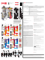
Componenti e connessioni idrauliche (g.1)
1Valvola deviatrice
2Attuatore per valvola deviatrice (Codice di completamento)
3Defangatore magnetico
4Valvole di intercettazione a sfera sui circuiti di ritorno
5Valvole di intercettazione a sfera sui circuiti di mandata
6Kit circolatore con valvola di ritegno / Kit tronchetto per circolatore con valvola di ritegno
(Codici di completamento)
7Telaio metallico per installazione a parete
ARitorno verso pompa di calore
BMandata da pompa di calore
CMandata verso bollitore acqua sanitaria
DRitorno da bollitore acqua sanitaria
EMandata verso puffer impianto di climatizzazione
FRitorno da puffer impianto di climatizzazione
GMandata verso impianto di riscaldamento
HRitorno dall’impianto di riscaldamento
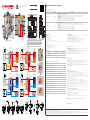
Funzionamento invernale
Solo riscaldamento (g.2a). In inverno il uido termovettore caldo proveniente dalla pompa di
calore entra nel modulo idronico e viene deviato verso l’impianto di riscaldamento. La portata non
richiesta dal riscaldamento carica il puer dell’impianto con la funzione di volano termico.
Riscaldamento e acqua calda sanitaria (g.2b). In inverno il uido termovettore caldo proveniente
dalla pompa di calore entra nel modulo idronico e viene deviato verso il bollitore per la produzione
di acqua calda sanitaria. Dal lato riscaldamento la portata viene prelevata dal puer. Il volano termico
garantisce quindi continuità nell’erogazione della potenza all’impianto.
NOTA. È importante che il puffer abbia una capacità minima adeguata alla potenza dell’impianto.
Funzionamento estivo
Solo rarescamento (g.3a). In estate il uido termovettore freddo proveniente dalla pompa di
calore entra nel modulo idronico e viene deviato verso l’impianto di rarescamento. La portata non
richiesta dal rarescamento carica il puer dell’impianto con la funzione di volano termico.
Rarescamento e acqua calda sanitaria (g.3b). In estate il uido termovettore caldo proveniente
dalla pompa di calore entra nel modulo idronico e viene deviato verso il bollitore per la produzione di
acqua calda sanitaria. Dal lato rarescamento la portata viene prelevata dal puer. Il volano termico
garantisce quindi continuità nell’erogazione della potenza all’impianto.
NOTA. È importante che il puffer abbia una capacità minima adeguata alla potenza dell’impianto.
Installazione (g.4)
AVVERTENZA. Prima di installare il modulo, si consiglia di vericare le condizioni operative dell’impianto, quali pressione e
temperatura, per garantire che siano comprese entro il campo di funzionamento. È importante che l’accesso al modulo sia libero
per eventuali manutenzioni.
Il modulo idronico R586HPI deve essere installato in posizione verticale a parete, utilizzando tasselli
ad espansione adatti al tipo di parete e al peso dei dispositivi da sorreggere.
AVVERTENZA. Il defangatore è dotato di un magnete che provoca campi magnetici , possibile causa di danni ad
apparecchiature elettroniche (compresi pacemaker ) che siano poste in prossimità.
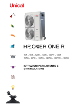
Pulizia del defangatore magnetico (g.5a)
Il modulo idronico R586HPI è provvisto di un defangatore magnetico (Componenti - Rif.3) in grado
di pulire l’acqua dell’impianto di climatizzazione dalle impurità, prima che ritorni verso la pompa di
calore. Durante il funzionamento dell’impianto, le impurità si depositano sulla supercie del pozzetto
contenente il magnete e sul fondo del defangatore. La pulizia del defangatore può essere eettuata
senza doverlo smontare e spegnere l’impianto; tuttavia per un’azione più ecace è ideale eseguire
queste operazioni in assenza di usso all’interno del defangatore.
Per pulire il defangatore e rimuovere le impurità procedere come segue:
1) chiudere le valvole di intercettazione a sfera a monte e a valle del defangatore;
2) rimuovere il magnete dal proprio pozzetto, svitandolo in senso antiorario con una chiave a brugola
da 5 mm; le impurità ferrose che si erano accumulate sulla supercie del pozzetto si depositeranno
all’interno del defangatore;
3) dopo aver atteso qualche minuto, prendere il tappo del rubinetto di scarico e posizionarlo sul
fondo del rubinetto stesso, quindi ruotarlo in senso antiorario per aprire il rubinetto e scaricare le
impurità presenti nel defangatore;
4) una volta che le impurità saranno fuoriuscite, chiudere il rubinetto di scarico e inserire il magnete
nel proprio pozzetto, avvitandolo in senso orario.
5) aprire le valvole di intercettazione a sfera a monte e a valle del defangatore e ripristinare il normale
funzionamento.
Pulizia del ltro metallico del defangatore (g.5b)
Per una migliore pulizia è possibile rimuovere il ltro nel seguente modo:
1) spegnere l’impianto e chiudere le valvole di intercettazione a sfera a monte e a valle del
defangatore;
2) svitare in senso antiorario la base del defangatore;
3) rimuovere il ltro dal defangatore e lavarlo sotto acqua corrente;
4) reinserire il ltro ed avvitare nuovamente la base del defangatore;
5) aprire le valvole di intercettazione a sfera a monte e a valle del defangatore e ripristinare il normale
funzionamento.
AVVERTENZA. Prevedere una valvola di sfogo aria nel circuito dell’impianto, per espellere l’aria accumulata dopo le fasi di
manutenzione e pulizia dei componenti.
Manutenzione
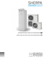
Dimensioni (g.6)

Instruction
047U59378
05/2023
Giacomini S.p.A.
Via per Alzo 39, 28017 San Maurizio d’Opaglio (NO) Italia
+39 0322 923372 - giacomini.com
R586HPI + COMPLETION CODES
3
4
2
1
6
7
5
F
HB GA
D
E
C
(g.1)
VIDEO TUTORIAL
G H I L
X C
M S UT
P Q
ON
B
Y
V
R
FE
A
D
Ø
(g.6)
A B C D E F G H I L M N
440 540 244 190 115 135 138 52 52 64 135 111
O P Q R S T U V Ø X Y
220 157 331 52 80 94 74 588 13 410 510 [mm]
R586HPI
R148HP
R148HP
THERMAL
STORAGE
TANK
HEAT PUMP
HEATING
SYSTEM
HDW STORAGE (g.2a)
R586HPI
R148HP
R148HP
THERMAL
STORAGE
TANK
HEAT PUMP
COOLING
SYSTEM
HDW STORAGE (g.3a)
THERMAL
STORAGE
TANK
HEAT PUMP
HEATING
SYSTEM
R586HPI
R148HP
R148HP
HDW STORAGE (g.2b)
R586HPI
R148HP
R148HP
THERMAL
STORAGE
TANK
HEAT PUMP
HDW STORAGE
COOLING
SYSTEM
(g.3b)
(g.4)
5 mm
CLOSE
CLOSE
CLOSE
CLOSE
OPEN
OPEN
5 mm
CLOSE
CLOSE
CLOSE
CLOSE
1 2 3 4 5
(g.5a)
CLOSE
CLOSE
OPEN
OPEN
OFF
1 2 3 4 5
(g.5b)
Safety Warning. Installation, commissioning and periodical maintenance of the product must be carried out by qualied operators in compliance with national regulations and/or local standards. A qualied installer must take all required measures, including use of
Individual Protection Devices, for his and others’ safety. An improper installation may damage people, animals or objects towards which Giacomini S.p.A. may not be held liable.
Package Disposal. Carton boxes: paper recycling. Plastic bags and bubble wrap: plastic recycling.
Product Disposal. Do not dispose of product as municipal waste at the end of its life cycle. Dispose of product at a special recycling platform managed by local authorities or at retailers providing this type of service.
Additional information. For more information, go to giacomini.com or contact our technical assistance ser vice. This document provides only general indications. Giacomini S.p.A. may change at any time, without notice and for technical or commercial reasons, the items
included herewith. The information included in this technical sheet do not exempt the user from strictly complying with the rules and good practice standards in force.
Technical data
Performance
• Fluid: water, glycol-based solution (max 30 % of glycol)
• Temperature range: 5÷90 °C
• Max working pressure: 10 bar
• Dirt separator lter: 300 µm
• Magnetic induction of dirt separator: 13000 Gauss
• Time required for diverting valve rotation: 40 sec. or 8 sec. based on version
Materials
• Main components: brass
• Ball valve extended T-handles: plastic with red or blue plate
• Dirt separator lter: AISI 304 stainless steel
• Dirt separator magnet: neodymium (N42H)
• Gaskets: EPDM
Loss of pressure
PRODUCT CODE DIVERTING VALVE Kv DIRT SEPARATOR Kv
R586HPIY005 11,0 6,7
R586HPIY105 8,0 6,7
R586HPI Hydronic unit for heat pump
EN
Versions and product codes
PRODUCT CODE CONN. DIVERTING VALVE COMPLETION CODES
R586HPIY005 G 1”F
40-sec.
diverting valve
(R279D)
• K270Y101: actuator 230 V, for 40-sec diverting valve (R279D)
• K270Y102: actuator 24 V, for 40-sec diverting valve (R279D)
• R540FY002: contact thermometer, red color, scale 0÷120 °C, Ø 40 mm (to be installed on the T-handles of the ball valves instead of the colored plates)
• R540FY022: contact thermometer, blue color, scale 0÷120 °C, Ø 40 mm (to be installed on the T-handles of the ball valves instead of the colored plates)
• R586HPIW005: insulation
• P76WHPIY001: Wilo Para 25/7 circulator kit, center distance 130 mm, with ball valve and check valve
• P76WHPIY002: Wilo Para 25/7 circulator kit, center distance 180 mm, with ball valve and check valve
• R197HPIY001: spacer kit for circulator installation, center distance 130 mm, with ball valve and check valve
• R197HPIY002 spacer kit for circulator installation, center distance 180 mm, with ball valve and check valve
R586HPIY105 G 1”F 8-sec.
diverting valve
• K270Y211: actuator 230 V, for 8-sec diverting valve
• R540FY002: contact thermometer, red color, scale 0÷120 °C, Ø 40 mm (to be installed on the T-handles of the ball valves instead of the colored plates)
• R540FY022: contact thermometer, blue color, scale 0÷120 °C, Ø 40 mm (to be installed on the T-handles of the ball valves instead of the colored plates)
• R586HPIW105: insulation
• P76WHPIY001: Wilo Para 25/7 circulator kit, center distance 130 mm, with ball valve and check valve
• P76WHPIY002: Wilo Para 25/7 circulator kit, center distance 180 mm, with ball valve and check valve
• R197HPIY001: spacer kit for circulator installation, center distance 130 mm, with ball valve and check valve
• R197HPIY002 spacer kit for circulator installation, center distance 180 mm, with ball valve and check valve
Components and hydraulic connections (g.1)
1Diverting valve
2Diverting valve actuator (Completion code)
3Magnetic dirt separator
4Shut-off ball valves on return circuits
5Shut-off ball valves on delivery circuits
6Circulator kit with check valve / Spacer kit for circulator with check valve (Completion codes)
7Metal frame for wall tting
AReturn to heat pump
BDelivery from heat pump
CDelivery to domestic water storage
DReturn from domestic water storage
EDelivery to thermal storage tank of HVAC system
FReturn from thermal storage tank of HVAC system
GDelivery to heating system
HReturn from heating system
Winter operation
Heating only (g.2a). In winter, the main ow rate coming from the heat pump enters the hydronic
unit then is diverted towards the heating system.
The exceeding part is directed to the thermal storage tank.
Heating and hot domestic water (g.2b). In winter, the main ow rate coming from the heat pump
enters the hydronic unit then is diverted towards the HDW storage for HDW production.
The heating system is supplied by the thermal storage tank.
NOTE. The thermal storage tank must feature a minimum capacity suitable for the system power.
Summer operation
Only cooling (g.3a). In summer, the main ow rate coming from the heat pump enters the hydronic
unit then is diverted towards the cooling system.
The exceeding part is directed to the thermal storage tank.
Cooling and hot domestic water (g.3b). In summer, the main ow rate coming from the heat pump
enters the hydronic unit then is diverted towards the HDW storage for HDW production.
The cooling system is supplied by the thermal storage tank.
NOTE. The thermal storage tank must feature a minimum capacity suitable for the system power.
Installation (g.4)
WARNING. Before installing the unit, check the system working conditions, such as pressure and temperature, to make sure
they are within the working range. Access to the unit must be unencumbered to perform maintenance.
The R586HPI hydronic unit must be installed vertically on wall, by using screw anchors suitable to
the type of wall and weight of the devices they to be supported.
WARNING. The dir t separator is provided with a magnet that generates magnetic elds that may damage electronic devices
(including pacemakers ) nearby.
Cleaning the magnetic dirt separator (g.5a)
The R586HPI hydronic unit includes a magnetic dirt separator (Components - Ref.3) that removes the
debris from the HVAC system water before it ows back to the heat pump.
The debris collects on the surface of the housing containing the magnet and on the bottom of the
dirt separator. There is no need to turn o the system and disassemble the dirt separator to clean
it; however, for ideal cleaning, the operations below should be carried out when there is no water
running through the dirt separator.
Follow these steps to clean the dirt separator and remove any debris:
1) close the shut-o ball valves upstream and downstream of the dirt separator;
2) remove the magnet from its housing by rotating it in counterclockwise direction with a 5-mm
Allen wrench; the ferrous debris collected on the housing surface will rest inside the dirt separator;
3) wait a few minutes then place the drain cock cap on the bottom of the cock, turn the cock in
counterclockwise direction to open it and remove the debris from the dirt separator;
4) once the debris has been removed, close the drain cock, replace the magnet in its housing and
tighten it in clockwise direction.
5) open the shut-o ball valves upstream and downstream of the dirt separator, then resume regular
opration.
Cleaning the dirt separator metal lter (g.5b)
To properly clean the dirt separator, remove the lter following the steps below:
1) turn o the system and close the shut-o ball valves upstream and downstream of the dirt
separator;
2) loosen the dirt separator base by turning it in counterclockwise direction;
3) remove the lter and rinse it under running water;
4) replace the lter and retighten the dirt separator base;
5) open the shut-o ball valves upstream and downstream of the dirt separator, then resume regular
opration.
WARNING. Install an air vent valve on the system circuit to release the air after servicing and cleaning the components.
Maintenance
Dimensions (g.6)
-
 1
1
-
 2
2


in altre lingue
Documenti correlati
Altri documenti
-
Ferroli 3542B320 Hydraulic Kit for Hybrid Systems Manuale utente
-
Watts DSPN Series Guida d'installazione
-
IVAR EQUICOMPACT Manuale utente
-
Olimpia Splendid Sherpa AQUADUE OS-CETNH48EI Manuale del proprietario
-
 Unical HP_OWER ONE R Guida d'installazione
-
La Nordica Assembled and combined ACS Kit 2.0 Manuale del proprietario
-
-
 Olimpia Splendid Sherpa® AQUADUE TOWER Guida d'installazione
-
Immergas 3.031810 Manuale utente
-
CIAT AQUACIAT POWER ILD R-32 Manuale utente

