IVAR EQUICOMPACT Manuale utente
- Categoria
- Misurazione, test
- Tipo
- Manuale utente


L’installazione e la messa in opera di EQUICOMPACT vanno effettuate esclusivamente da personale qualificato
in accordo con i regolamenti nazionali e/o i relativi requisiti locali. È importante seguire attentamente le
istruzioni fornite nel seguito per prevenire danni al sistema e all’installatore.
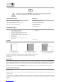
Condizioni di utilizzo
Fluido a contatto: acqua/miscele acqua-glicole
Max pressione statica operativa: 10 bar
Campo di temperatura del fluido: 3÷90 °C
Max pressione differenziale sulla valvola di zona: 0,5 bar
Attacchi valvole a sfera: 3/4’’ tenuta piatta
Materiali
Corpo: ottone CW617N
Linee sanitarie: rame semicrudo
Elementi di tenuta: EPDM perossidico
Tronchetti contatori: PA + 30% FV
Guscio di isolamento: PP
Cassette metalliche: acciaio
Cassette isolate: EPP
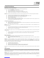
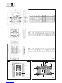
A Blocco calore (dettagli in Fig. 3)
1. Valvole a sfera di intercettazione
2. Valvola di bilanciamento statico
3. Pozzetto per sonda mandata contatore di calore
4. Valvola di zona a 2-vie a pistone
5. Pozzetto per regolatore di pressione differenziale (*)
6. Telaio metallico
7. Filtro 500 micron
8. Tronchetto contatore di calore (3/4’’ int. 110 mm o 1’’
int. 130 mm)
B Linee sanitarie (ove previste)
C Alloggiamento
Componenti (Fig. 2)
Versioni
EQUICOMPACT può essere acquistato in componenti singoli o preassemblato. Le configurazioni preassemblate sono disponibili nelle seguenti varianti:
Le varianti in cassetta metallica includono l’isolamento singolo in polipropilene del solo blocco calore.
La variante con guscio da incasso in polipropilene non richiede ulteriori isolamenti singoli.
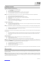
Ingombri in Fig. 1.
Descrizione
I moduli di utenza sono gruppi polifunzionali che riuniscono in un solo punto i dispositivi di contabilizzazione diretta e valvole di controllo. EQUICOMPACT
è una soluzione versatile e dall’ingombro ridotto per la gestione del calore. La sua caratteristica valvola di zona a due vie lo rende adatto all’utilizzo con
pompe a portata variabile: questo binomio permette di ridurre le portate mediamente circolanti nell’impianto, e quindi di risparmiare energia, ma anche
di ottenere temperature di ritorno più basse, aspetto quest’ultimo particolarmente vantaggioso con caldaie a condensazione e teleriscaldamento.
Attenzione. La mancanza di by-pass rende EQUICOMPACT adatto ai soli impianti con pompe a velocità variabile correttamente dimensionate.
Caratteristiche idrauliche
Il coefficiente di flusso massimo del blocco calore e il grafico relativo sono riportati in Fig. 4a (valore complessivo mandata + ritorno, non comprensivo
di contatore di calore).
Attenzione. La perdita di carico complessiva del modulo va calcolata sommando la perdita che si ricava dal grafico di Fig. 4a alla perdita di carico del
contatore di calore.
Se in EQUICOMPACT viene installato un contatore di calore a turbina presente sul catalogo IVAR, è possibile ricavare le caratteristiche del modulo
comprensivo di misuratore direttamente dalle Fig. 4b (contatore con attacchi 3/4’’ e interasse 110 mm) e Fig. 4c (contatore con attacchi 1’’ e interasse
130 mm).
CL - In cassetta metallica da incasso con
portello intonacabile art. AC 860L
IL - In guscio da incasso in polipropilene con
portello standard art. AC 860IB
CB - In cassetta metallica da
incasso standard art. AC 860B
(*) non incluso
IT
2
300451-04-17

Istruzioni di installazione
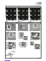
Installazione e allacciamenti idraulici (Fig. 5)
Ricavare una nicchia nel muro di dimensioni opportune facendo riferimento agli ingombri di Fig. 1.
(a) Posizionare EQUICOMPACT al centro della nicchia
(b) Rimuovere l’isolamento del blocco calore (se previsto dal modello)
(c) Collegare le tubazioni di ritorno sia sul primario che sul secondario del blocco calore
(d) Collegare le tubazioni di mandata sia sul primario che sul secondario del blocco calore
Attenzione. Il contatto con fluido ad alta temperatura può provocare ustioni anche gravi. Dotarsi dei necessari dispositivi di protezione individuale.
(e) Aprire le quattro valvole di intercettazione (due rosse e due blu) del blocco calore
(f) Con l’aiuto di una chiave a brugola da 8 mm, rimuovere il tappo dalla valvola di bilanciamento statico
(g) Aprire completamente la valvola, avendo cura che l’intaglio sia parallelo al flusso
(h) Effettuare il lavaggio dell’impianto
(i) Richiudere le valvole di intercettazione rosse del blocco calore
(j) Con l’aiuto di una chiave a brugola da 8 mm, rimuovere il tappo a chiusura del portafiltro. Rimuovere la cartuccia, pulirla con cura e
reinserirla nella sede, quindi riposizionare il tappo e serrarlo.
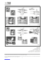
Installazione dei contatori (Fig. 6)
(a) Chiudere le valvole di intercettazione del blocco calore
(b) Allentare i dadi agli estremi del tronchetto DIMA e rimuoverlo. Posizionare due guarnizioni nuove, inserire il contatore di calore al posto
del distanziale e serrare i dadi senza forzare
Attenzione. Prestare estrema attenzione al verso del flusso. Un montaggio errato del contatore impedisce la corretta contabilizzazione e può
danneggiare il dispositivo.
(c) Con l’aiuto di una chiave esagonale da 15 mm, svitare e rimuovere il tappo da pozzetto portasonda (3 in Fig. 3) e inserire la sonda di
mandata del contatore di calore seguendo le istruzioni del fabbricante del dispositivo
(d) Piombare il contatore e la sua sonda di mandata
I punti seguenti sono da eseguire solo nel caso in cui il modulo preveda l’installazione di uno o più contatori volumetrici, e vanno ripetuti per ogni linea
sanitaria presente.
(e) Dopo aver controllato che le valvole della linea sanitaria siano chiuse, allentare i dadi agli estremi del tronchetto DIMA e rimuoverlo.
Posizionare le guarnizioni, inserire il contatore volumetrico al posto del distanziale e serrare i dadi senza forzare
(f) Piombare il contatore
Messa in opera (Fig. 7)
Secondo le modalità previste dal progettista, effettuare il bilanciamento idraulico statico dell’utenza procedendo come segue:
(a) Aprire le valvole di intercettazione del blocco calore
(b) Aggiustare lentamente l’apertura del selettore di bilanciamento finché sul display del contatore di calore non si registra la portata di
progetto
Attenzione. Se si desidera equipaggiare il sistema con dispositivi di bilanciamento dinamico, è possibile utilizzare valvole con cartuccia per la
stabilizzazione della portata oppure valvole di controllo della pressione differenziale, da installare al di fuori di EQUICOMPACT. Se la valvola di controllo
della pressione differenziale è adatta al montaggio sulla linea di ritorno, è possibile sfruttare l’apposito pozzetto (5 in Fig. 3) per l’inserimento della
presa di alta pressione. Il filetto di attacco è M10x1 a tenuta morbida.
(c) Completata la taratura, rimontare il tappo
(d) Piombare la valvola grazie alle apposite asole
(e) Riaprire tutte le valvole di intercettazione, sia sul blocco calore che sulle linee sanitarie
(f) Riposizionare la parte superiore del guscio di isolamento (se prevista dalla versione).
Per la versione con portello intonacabile, intonacare il portello a parte. Realizzare le opere di muratura, quindi posizionare il portello a operazioni
ultimate.
Altri accessori
La valvola di zona 4 in Fig. 3 può essere comandata da un attuatore collegato a un termostato ambiente. IVAR propone le testine elettrotermiche
normalmente chiuse cod. 501508 (230 V) o cod. 501524 (24 V) in abbinamento al cronotermostato cod. 580012 (solo caldo) o cod. 580015 (caldo e
freddo), acquistabili separatamente.
Attenzione. Seguire le istruzioni dei dispositivi elettronici per una corretta installazione. In particolare, se si montano testine elettrotermiche
normalmente chiuse dotate di funzione “first open” (come i dispositivi cod. 501508 o cod. 501524), considerare che le testine vengono fornite in
posizione di apertura, e solo l’applicazione della tensione di esercizio per più di 6 min disattiverà la funzione. Terminato tale ciclo iniziale, la testina sarà
regolarmente aperta se alimentata e chiusa in caso contrario.
3
300451-04-17

The installation and commissioning of EQUICOMPACT system must be exclusively performed by qualified
personnel in accordance with the national guidelines and/or the relative local requirements. It is important
that the instructions here provided be followed in order to prevent damage to the system and/or personal
injuries
Conditions of use
Contact fluid: water/water-glycol mixtures
Max static working pressure: 10 bar
Fluid temperature: 3÷90 °C
Max differential pressure across the zone valve: 0.5 bar
Ball valve connections: 3/4’’ flat seal
Materials
Body: CW617N brass
Domestic water lines: half-hard copper
Seal parts: peroxide EPDM
Meter templates: PA + 30% GF
Insulation: PP
Metal boxes: steel
Insulated boxes: EPP
A A Heating unit (details in in Fig. 3)
1. Shut-off ball valves
2. Static balancing valve
3. Heat meter flow sensor port
4. 2-way piston zone valve
5. Port for differential pressure controller capillary (*)
6. Metal frame
7. Filter 500 micron
8. Heat meter spacer (3/4’’ port-to-port 110 mm or 1’’
port-to-port 130 mm)
B Domestic water lines (where provided)
C Housing
Components (Fig. 2)
Versions
EQUICOMPACT can be purchased as spare components or as a pre-built unit. Pre-built configuration are available in the following variants:
Variants in metal box include individual polypropylene insulation for heat metering unit.
Variant in polypropylene recessed shell does not require the addition of individual insulation shells.
Dimensions in Fig. 1
Description
User modules are multi-functional groups combining metering devices and control valves in a single unit. EQUICOMPACT is a flexible small-footprint
solution for heating management. Its characteristics two-way zone valve makes it suitable to the application with variable-speed pumps: this
combination allows to reduce mean flow rates circulating through the plant, thus saving energy, and to obtain lower return temperatures, which is
particularly convenient with condensing boilers and district heating.
Warning. The lack of a by-pass makes EQUICOMPACT applicable only with a properly-sized pump working at variable-speed.
Hydraulic features
The maximum flow coefficient value for the heating unit and the relative chart are reported in Fig. 4a (flow + return, without heat meter).
Warning. The overall module pressure drop is computed by summing up the pressure loss obtained by Fig. 4a and the pressure loss of the heat meter
at the same flow rate.
If a turbine heat meter included in IVAR catalogue is installed in EQUICOMPACT, overall hydraulic performance of the module can be obtained directly by
Fig. 4b (heat meter with 3/4’’ threads and 110 mm port-to-port distance) and Fig. 4c (heat meter with 1’’ threads and 130 mm port-to-port distance).
CL - In recessed metal box with
plastering-ready door art. AC 860L
IL - In recessed polypropylene shell with
standard door art. AC 860IB
CB - In standard recessed
metal box art. AC 860B
(*) not included
EN
4
300451-04-17

Installation instructions
Installation and hydraulic connections (Fig. 5)
Prepare a recess in the wall having the correct size (refer to Fig. 1)
(a) Position EQUICOMPACT into the centre of the recess
(b) Remove the heating unit insulation (if provided)
(c) Connect return piping both to the primary and to the secondary side of the heating unit
(d) Connect flow piping both to the primary and to the secondary side of the heating unit
Warning. The contact with high-temperature fluid can cause even serious scalding. Use the adequate personal protection equipment (PPE).
(e) Open the four (two red and two blue) heating unit shut-off valves
(f) Remove the plug from the static balancing valve by means of an 8-mm Allen key
(g) Drive the valve fully open, making sure that the incision is parallel to the flow direction
(h) Wash the plant
(i) Close the red shut-off valves of the heating unit
(j) By means of an 8-mm Allen key, remove the plug sealing the strainer housing. Remove the strainer cartridge, wash it carefully, the put
it back into the housing. Put the plug back and tighten it.
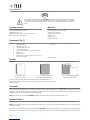
Installation of meters (Fig. 6)
(a) Close the shut-off valves of the heating unit
(b) Loosen the nuts at the endpoints of the template, then remove it. Position two new gaskets and the heat meter instead of the template,
then tighten the nuts without forcing too much
Warning. Pay extreme attention to flow direction. A wrong installation of the heat meter precludes the correct metering and may damage the device.
(c) By means of a 15-mm wrench, unscrew and remove the plug from the sensor pocket (3 in Fig. 3) and insert the heat meter flow sensor
by following the instructions provided by the manufacturer of the device
(d) Seal the meter and the flow sensor
The following steps must be carried out only if the application requires the installation of one or more volumetric meters, and should be repeated for
each domestic line.
(e) After checking that both the shut-off valves of the domestic line are closed, loosen the nuts at the endpoints of the template, then
remove it. Position two new gaskets and the water meter instead of the template, then tighten the nuts without forcing too much
(f) Seal the meter.
Commissioning (Fig. 7)
According to the designer specifications, make the static balancing of the user plant by following these steps:
(a) Open the heating unit shut-off valves
(b) Slowly adjust the balancing selector position until the design flow rate is showed by the heat meter display
Warning. If the installation is to be equipped with dynamic balancing devices, either flow stabilising valves or differential pressure controlling valves can
be installed outside EQUICOMPACT unit. In case of differential pressure control valve for return mounting, a dedicated pocket (5 in Fig. 3) can be used
for the connection of the high-pressure capillary probe. The connection thread is soft-seal M10x1.
(c) Once the adjustment has been completed, put back the plug
(d) Seal the valve using of the proper holes
(e) Open all the shut off valves, both on heating and domestic lines
(f) Put back the insulation shell (if provided).
In case of plastering-ready door, plaster the door aside. Complete the necessary masonry operations, then put back the plastered door once the work
is over.
Other accessories
Zone valve 4 in Fig. 3 can be controlled by an actuator wired to a room thermostat. IVAR offers normally closed electro-thermal heads cod. 501508
(230 V) or cod. 501524 (24 V) together with chrono-thermostat cod. 580012 (heating only) or cod. 580015 (heating/cooling). These components can
be purchased separately.
Warning. Follow the dedicated instructions of the electronic devices for their correct installation. In particular, if normally-closed electro-thermal heads
with “first open” function are installed (see cod. 501508 or cod. 501524), please consider that such devices are delivered in open state. This function
is permanently disengaged after the first 6 min of powered use at the working voltage. Once the initial cycle has been completed, the head will be
regularly open when powered, and closed otherwise.
5
300451-04-17

COD. ART. A B C D E F G H L M N
P
506575SI EQCP15 265 203 98 230 80 115 70 110 G ¾’’ G ¾’’ M10x1
M30x1.5
506575S EQCP15 - - - 230 80 - 70 110 G ¾’’ G ¾’’ M10x1
M30x1.5
506576SI EQCP25 265 203 98 230 80 115 70 130 G 1’’ G ¾’’ M10X1
M30X1.5
506576S EQCP25 - - - 230 80 - 70 130 G 1’’ G ¾’’ M10X1
M30X1.5
ART. COD. A B C D E F G H L M
AC 860B 200199 510 510 444 444 450 450 130 80 110 36
AC 860L 200299 520 520 442 442 450 450 130 80 110 36
ART. COD. A B C D E F G H L M
AC 860IB 506665B 530 530 400 400 470 470 130 80 92 43
Fig. 1
7
6
43
2
8
5
1
9
Fig. 3Fig. 2
C
A
B
6
300451-04-17


I.V.A.R. S.p.A.
Via IV Novembre, 181
25080 Prevalle (BS) – ITALY
T. +39 030 68028 – F. +39 030 6801329
[email protected] – www.ivar-group.com
I.V.A.R. S.p.A. si riserva il diritto di apportare miglioramenti e modifiche ai prodotti e alla relativa documentazione in qualunque momento e senza preavviso. Tutti i diritti sono
riservati. La riproduzione completa o parziale è vietata senza il previo consenso del proprietario del copyright.
I.V.A.R. S.p.A. reserves the right to make enhancements and changes to products and relative documentation at any time without prior notice. All rights reserved. Reproduction,
even partial, is forbidden without prior permission by the copyright owner.
Fig. 6
(a)
(d)
(b)
(e)
(c)
(f)
Fig. 6
(a)
(d)
(b)
(e)
(c)
(f)
8
300451-04-17
-
 1
1
-
 2
2
-
 3
3
-
 4
4
-
 5
5
-
 6
6
-
 7
7
-
 8
8


IVAR EQUICOMPACT Manuale utente
- Categoria
- Misurazione, test
- Tipo
- Manuale utente
in altre lingue
- English: IVAR EQUICOMPACT User manual
Documenti correlati
Altri documenti
-
Riello Start Condens 25 IS Installer And User Manual
-
Giacomini R553FKDB Istruzioni per l'uso
-
Ducati monster S4 fogarty 2002 Workshop Manual
-
-
 Biasi ADAPTA TOWER 107/114 Guida d'installazione
-
BALTUR TBML 1600 ME 50Hz Use and Maintenance Manual
-
-
-
