
MADE IN ITALY
design & production
REGOLATORE Termoprodotti Digitale cod.6012022
KIT SEPARATORE IMPIANTO 6012021 2.0 6012027
KIT ACS Assemblato SEMPLICE 6012014 2.0 6012025
KIT ACS Assemblato COMBINATO 6012015 2.0 6012026
IT-EN-DE-FR-DE 6092000 - Rev.09
ACCESSORI
PER TERMOPRODOTTI

ITALIANO ...........................................................................................................4
ENGLISH ............................................................................................................9
DEUTSCH .......................................................................................................... 14
FRANCAIS ......................................................................................................... 19
ESPAÑOL ...........................................................................................................24
2

Das auf dem Produkt oder derVerpackung angebrachte Symbol besagt, dass das Produkt nicht als normaler Hausmull anzusehen ist, sondern bei
speziellen Sammelstellen für das Recycling von Elelktro- und Elektronik-Altgeraten abzugeben ist. Durch die ordnungsgemäße Entsorgung dieses
Produktes werden mögliche negative Folgen vermieden, die aus einer unsachgemäßen Entsorgung. des Produktes entstehen konnten. Ausführlichere
Informationen zum Recycling, dieses Produktes liefern das Gemeindeamt, der örtliche Müllentsorgungsdienst oder der Händler, bei dem das Produkt
gekauft wurde
INFORMAZIONI AL UTENTE SULLO SMALTIMENTO DELLE APPARECCHIATURE DA PARTE DEI PRIVATI
NEL TERRITORIO DELL’UNIONE EUROPEA
Ai sensi dell’art.13 del decreto legislativo 25 luglio 2005, n.151 «attuazione delle direttive 2002/95/CE e 2003/1 08/CE, relative
sostanze alla riduzione dell’uso di sostanze pericolose nelle apparecchiature elettriche ed elettroniche, nonché allo smaltimento dei
riuti». il simbolo del cassonetto barrato riportato sull’apparecchiatura o sulla confezione indica che il prodotto alla ne della propria
vita utile deve essere raccolto separatamente dagli altri riuti. l’utente dovrà, pertanto, conferire l’apparecchiatura giunta a ne vita agli
idonei centri di raccolta differenziata dei riuti elettronici ed elettrotecnici, oppure riconsegnarla al rivenditore al momento dell’acquisto
di una nuova apparecchiatura di tipo equivalente, in ragione di uno a uno. L’adeguata raccolta differenziata per l’awio successivo
dell’apparecchiatura e dismessa al riciclaggio, al trattamento e allo smaltimento ambientalmente compatibile, contribuisce ad evitare
possibili effetti negativi sull’ambiente e sulla salute e favorisca il reimpiego e/o riciclo dei materiali di cui è composta l’apparecchiatura.
Lo smaltimento abusivo del prodotto da parte dell’utente comporta l’applicazione delle sanzioni amministrative previste dalla normativa
vigente, di cui al digs n. 22/1997 (articolo 50 e seguenti del digs n. 22/1997).
This symbol appearing on a product or its packaging indicates that the product must not be considered os normal household waste, but must be token to a
special waste collection centre for recycling electric and electronic appliances. Disposing of this product appropriately helps ovoid any potentially negative
consequences which could arise from its incorrect disposal. For more detailed information on recyding of this product, contact your local council, the local
waste disposal service or the shop where you bought the product..
El símbolo del contenedor tachado, aplicado en el embalaje o en el producto, indica que éste no debe desecharse junto a los residuos domésticos
sino depositarse en un punto de recogido esp.ecíco para aparatos eléctricos y electrónicos. El reciclaje y. la eliminación ecocompatible del producto
contribuyen a proteger el medio ambiente y la salud de la población. Pora más información sobre el reciclaje de este producto, consulte con el Ayuntamiento
de su ciudad, con el servicio local de eliminación de residuos o con el comercIo donde te, ha adquirido.
O símbolo em questão, quando aplicado no produto ou embalagem, indica que o produto não deve ser considerado lixo doméstico normal e deve ser
levado a um centro de recolha para reciclagem de equipamentos eléctricos. Eliminando este produto nas devidas condições estar·se·á a contribuir para
evitar as potenciais conseqüências negativas decorrentes de uma eliminação inadequada do mesmo. Para mais informações sobre a reciclagem do
produto, contacte o serviço especializado da Câmara municipal, o serviço local de eliminação de desperdícios ou o comerciante onde o adquiriu.
Le symbole en question appliqué sur le produit ou sur l’emballage indique que le produit ne doit pas être considéré comme un déchet domestique normal,
mais doit être déposé dans un point de collecte différenciée approprié au recyclage d’appareils électriques et électroniques.
Le respect de cette norme permet d’éviter toute conséquence négative qui pourrait dériver d’une élimination du produit de manière non adéquate. Pour
des informations plus détaillées sur le recyclage de ce produit, contacter le service de la mairie compétent, le service local d‘élimination des déchets ou
le magasin auprès duquel le produit a été acheté.
3

ITALIANO
ATTENZIONE
ESEGUIRE LE INDICAZIONI DI MONTAGGIO SEMPRE NELLA MASSIMA
SICUREZZA E SCOLLEGATI DALLA RETE ELETTRICA!
ATTENERSI TASSATIVAMENTE ALLE INDICAZIONI DI MONTAGGIO DESCRITTE!
ITALIANO - INDICE
INSTALLAZIONE ...........................................................................................................................................................................5
REGOLATORE ELETTRONICO DIGITALE PER TERMOPRODOTTI AD ACQUA .........................................................................5
FUNZIONAMENTO .................................................................................................................................................................................................................. 5
ACCENSIONE E SPEGNIMENTO ..................................................................................................................................................................................... 5
DISPLAY ................................................................................................................................................................................................................................... 5
MENU IMPOSTAZIONI ....................................................................................................................................................................................................... 6
CIRCOLATORE 1 .................................................................................................................................................................................................................... 6
CIRCOLATORE 2 .................................................................................................................................................................................................................... 6
TEMPERATURA ACQUA CALDA ..................................................................................................................................................................................... 6
ANTIGELO ............................................................................................................................................................................................................................... 6
ANTIBLOCCO ......................................................................................................................................................................................................................... 6
ALLARME SOVRATEMPERATURA .................................................................................................................................................................................. 6
ALLARME SONDA GUASTA .............................................................................................................................................................................................. 6
SCARICO ARIA....................................................................................................................................................................................................................... 6
FUNZIONI EXTRA ..................................................................................................................................................................................................................... 6
VALVOLA A TRE VIE ............................................................................................................................................................................................................. 7
BOILER ATTIVO ..................................................................................................................................................................................................................... 7
PUFFER ATTIVO .................................................................................................................................................................................................................... 7
BOILER E PUFFER ATTIVI ................................................................................................................................................................................................... 7
COLLEGAMENTI ELETTRICI ................................................................................................................................................................................................. 7
DIAGRAMMA DI FLUSSO ...................................................................................................................................................................................................... 8
KIT ACQUA CALDA .......................................................................................................................................................................8
COLLEGAMENTO IDRAULICO ............................................................................................................................................................................................. 8
FUNZIONAMENTO .................................................................................................................................................................................................................. 8
SCHEMA DI INSTALLAZIONE. .................................................................................................................................................. 29
COLLEGAMENTI DISPLAY......................................................................................................................................................... 38
CARATTERISTICHE TECNICHE DISPLAY. ........................................................................................................................................................................39
4

1 2 3 4 5 6
T4 T3 T2
T1
ITALIANO
INSTALLAZIONE
Tutte le operazioni devono essere fatte con l’alimentazione disinserita dalla rete elettrica.
L’installazione, i relativi collegamenti dell’impianto, la messa in servizio e la verica del corretto funzionamento devono essere eseguiti a
regola d’arte da personale professionalmente autorizzato nel pieno rispetto delle norme vigenti, sia nazionali, regionali, provinciali e comunali
presenti nel paese in cui è stato installato l’apparecchio, nonché delle presenti istruzioni
La nostra responsabilità è limitata alla fornitura dell’apparecchio. Il suo impianto va realizzato in modo conforme alla regola dell’arte,
secondo le prescrizioni delle presenti istruzioni e le regole della professione, da personale qualicato, che agisce a nome di imprese
adatte ad assumere l’intera responsabilità dell’insieme dell’impianto.
NORDICA S.p.A. non è responsabile del prodotto modicato senza autorizzazione e tanto meno per l’uso di ricambi non originali.
AVVERTENZA: l’installazione, i collegamenti ed il collaudo devono essere adati a personale qualicato che opera rispettando le Norme
vigenti e seguono quanto riportato nel libretto di istruzioni del termoprodotto. Il corretto funzionamento del comando è garantito solamente
per circolatori e valvole omologati da NORDICA S.p.A.. L’uso improprio solleva il costruttore da ogni responsabilità.
AVVERTENZA: L’installazione del regolatore digitale per termoprodotti non deve assolutamente essere fatta sulla cappa di rivestimento o
vicino al termoprodotto, dove si potrebbe superare la massima temperatura di esercizio dichiarata nelle caratteristiche tecniche (60°C).
L’installazione deve essere fatta al di fuori delle zone di calore radiante o convettivo ed eventualmente con il montaggio della scatola
protettiva (Fornita come Optional). In ogni caso i componenti del termoregolatore non devono mai superare la temperatura di esercizio di
60°C.
REGOLATORE ELETTRONICO DIGITALE PER TERMOPRODOTTI AD ACQUA
FUNZIONAMENTO
Questo dispositivo elettronico digitale controlla l’avvio di due circolatori e: vedi capitolo FUNZIONI EXTRA.
Il corretto funzionamento del dispositivo è garantito solamente per circolatori e valvole omologati da NORDICA S.p.A..
NORDICA S.p.A. non risponde per l’uso improprio dell’apparecchio.
Dal menu interno si possono impostare:
• le informazioni visualizzate nel display in lingua (IT-EN-DE-FR);
• la temperatura in °C o °F;
• attivare o disattivare l’avvisatore acustico degli allarmi (Buzzer);
• cambiare l’intensità luminosa del display;
• accedere al menu tecnico.
ATTENZIONE: è assolutamente sconsigliato modicare i parametri all’interno del menu tecnico. Questa operazione deve essere fatta
esclusivamente da un centro di assistenza autorizzato dalla NORDICA S.p.A.
NORDICA S.p.A. non è responsabile del mal funzionamento del prodotto dovuto ai parametri del menu tecnico modicati senza
autorizzazione.
ACCENSIONE E SPEGNIMENTO
Avvengono tramite pressione prolungata del tasto T1. Lo stato (ON/OFF) verrà visualizzato sul display alternandosi alla temperatura rilevata
dalla sonda I1 all’interno della caldaia del termo prodotto.
DISPLAY
Led 1
Allarme (sovratemperatura acqua, sonda guasta,
antiblocco, antigelo)
Led 2 Puer in richiesta
Led 3 Boiler in richiesta
Led 4 Circolatore 1 in funzione
Led 5 Circolatore 2 in funzione
Led 6 Valvola 3 vie attiva
DISPLAY Temperatura mandata
Tasto 1 Accensione / Spegnimento. Uscita dai Menù
Tasto 2 Salita all’interno dei menù
Tasto 3 Discesa all’interno dei menù
Tasto 4 Entrata nei menù e conferma scelte
5

ITALIANO
MENU IMPOSTAZIONI
Fare riferimento al Capitolo DISPLAY.
LINGUA. Con una pressione prolungata del tasto MENU (T4) si accede al menù LINGUA. (Premere il tasto T1 per uscire dai menu).
Con una ulteriore breve pressione del tasto MENU è possibile modicare tramite i pulsanti T2 / T3, la lingua visualizzata (IT; EN; DE; FR). Premere
MENU per confermare la scelta.
BUZZER. Premere il tasto T2 per accedere al menu BUZZER (attivazione del segnale acustico). Premere il tasto MENU per attivare o disattivare
il segnale acustico, tramite i pulsanti T2 / T3 (ON / Off). Premere MENU per confermare la scelta.
IMPOSTA GRADI. Premere il tasto T2 per accedere al menu IMPOSTA GRADI (visualizza la temperatura in °C / °F). Premere il tasto MENU per
modicare, tramite i pulsanti T2 / T3, la visualizzazione della temperatura da °C a °F e viceversa. Premere MENU per confermare la scelta.
DISPLAY. Premere il tasto T2 per entrare nel menu DISPLAY (intensità luminosa da 0 a 100). Premere il tasto MENU per impostare l’intensità
desiderata del display, tramite i pulsanti T2 / T3, da 0 a 100. Premere MENU per confermare la scelta.
TARATURE TECNICHE. Premere il tasto T2 per entrare nel menu TARATURE TECNICHE.
ATTENZIONE: è assolutamente sconsigliato modicare i parametri all’interno del menu tecnico. Questa operazione deve essere fatta
esclusivamente da un Centro di Assistenza autorizzato dalla NORDICA S.p.A.. NORDICA S.p.A. non è responsabile del mal funzionamento
del prodotto dovuto ai parametri del menu tecnico modicati senza autorizzazione.
CIRCOLATORE 1
Il circolatore viene attivato dal regolatore con dispositivo acceso (ON) quando la temperatura rilevata dalla sonda I1 supera il valore impostato
SOGLIA OUT1=60°C (PR01). Viene disattivato quando la temperatura rilevata dalla sonda I1 scende al di sotto del valore impostato SOGLIA
OUT1 meno il valore di isteresi DELTA OUT1=5°C (PR02) ovvero sotto a 55°C. (Vedi schema 2, 4, 6 e 8).
CIRCOLATORE 2
Il circolatore viene attivato dal regolatore (se presente e collegato al regolatore come indicato al capitolo COLLEGAMENTI DISPLAY) con
dispositivo acceso (ON) quando la temperatura rilevata dalla sonda I1 supera il valore SOGLIA OUT2=70°C (PR03). Viene disattivato quando
la temperatura rilevata dalla sonda I1 scende al di sotto del valore impostato SOGLIA OUT2 meno il valore di isteresi DELTA OUT2=5°C (PR04)
ovvero sotto a 65°C (Vedi schema 1, 3, 5 e 7).
TEMPERATURA ACQUA CALDA
La temperatura dell’acqua viene visualizzata sul display.
Nel caso di sovratemperatura dell’acqua il dispositivo avverte l’utente con una segnalazione luminosa unita ad un segnale acustico, segnale
che può essere inserito o disinserito dalla funzione BUZZER del MENU.
Vedi ALLARME SOVRATEMPERATURA.
NOTA: La temperatura di attivazione dei circolatori è un’impostazione di fabbrica.
ANTIGELO
La funzione antigelo è sempre attiva nel dispositivo e interviene avviando il circolatore quando la temperatura rilevata dalla sonda è inferiore
a 5°C / 41°F (soglia non impostabile).
Quando la funzione antigelo è attiva, il LED 1 si accende e compare la scritta “ANTIGELO” nel display.
ANTIBLOCCO
La funzione ANTIBLOCCO avvia , per circa di 30 secondi, automaticamente le pompe collegate a questo regolatore dopo un lungo periodo di
inattività (~96 ore senza interruzione della tensione elettrica).
Quando la funzione ANTIBLOCCO interviene, sul display compare la scritta “ANTIBLOCCO”.
ATTENZIONE : anché la funzione ANTIBLOCCO non venga esclusa, lasciare sempre sotto tensione elettrica il regolatore digitale (display
con scritta OFF).
ALLARME SOVRATEMPERATURA
Quando la temperatura rilevata dalla sonda acqua supera gli 87°C / 188.6°F (soglia non impostabile), questo allarme interviene avviando i
circolatori.
Quando l’allarme interviene, il LED 1 si accende e compare la scritta “SOVRATEMPERATURA” nel display.
ALLARME SONDA GUASTA
Quando una sonda si guasta, questo allarme interviene attivando i circolatori.
Quando l’allarme interviene, il LED 1 si accende e compare la scritta “SONDA GUASTA I1 - I2 - I3” nel display.
SCARICO ARIA
L’aria presente all’interno dell’impianto idraulico causa rumorosità e può danneggiare i circolatori. La presenza d’aria può essere dovuta a
seguito dell’installazione del prodotto o di un qualsiasi altro intervento operato nell’impianto idraulico.
Scaricare l’eventuale aria presente all’interno dell’impianto agendo dal regolatore digitale nel seguente modo:
• l’acqua dell’impianto deve essere a temperatura ambiente;
• con il regolatore digitale su OFF, premere contemporaneamente i tasti T2 e T3. Sul display compare la scritta “SCARICO ARIA”.
• Premere il tasto T1 per disattivare la funzione SCARICO ARIA.
FUNZIONI EXTRA
Dal menù TARATURE TECNICO si accede ai sotto menù.
Dal menù IMPIANTO premendo T4 si accede ai settaggi del boiler e del puer. Premendo nuovamente T4 si scorrono i parametri. Premendo
T2 e T3 si modicano i parametri. Premendo nuovamente T4 si confermano le modiche e si passa al parametro successivo del menù, no a
ritornare al menù IMPIANTO.
6

ITALIANO
VALVOLA A TRE VIE
La valvola a tre vie viene attivata dal regolatore (se presente e collegata al regolatore come indicato al capitolo COLLEGAMENTI DISPLAY) con
dispositivo acceso (ON) quando la temperatura rilevata dalla sonda I1 supera il valore SOGLIA OUT1=60°C (PR01) ed il boiler è in condizione
di richiesta. Viene disattivata quando la temperatura rilevata dalla sonda I1 scende al di sotto del valore impostato SOGLIA OUT1=60°C meno
il valore di Isteresi DELTA OUT1=5°C (PR02) ovvero sotto a 55°C oppure quando il boiler non è più in condizione di richiesta (Vedi schema 3,
4, 7, 8).
BOILER ATTIVO
Per attivare il boiler settare il parametro PR08=ON e collegare la sonda I3 Optional (L= 2 metri) come indicato al capitolo COLLEGAMENTI
DISPLAY.
Il boiler va in condizione di richiesta con dispositivo acceso (ON) no a quando la temperatura rilevata dalla sonda I3 non raggiunge il valore di
SET BOILER MAX=60°C (PR09), a questo punto la richiesta è soddisfatta. Il boiler torna in condizione di richiesta quando la temperatura rilevata
dalla sonda I3 scende al di sotto del valore di SET BOILER MIN=30°C (PR10) (vedi schema 3, 4).
PUFFER ATTIVO
Per attivare il puer settare il parametro PR11=ON e collegare la sonda I2 Optional (L= 2 metri) come indicato al capitolo COLLEGAMENTI
DISPLAY.
Il puer va in condizione di richiesta con dispositivo acceso (ON) no a quando la dierenza tra la temperatura rilevata da I1 e la temperatura
rilevata dalla sonda I2 è maggiore del valore di DT ON=7°C (PR12). Quando la stessa dierenza scende al di sotto del valore di DT OFF=5°C
(PR13) il puer esce dalla condizione di richiesta (vedi schema 5, 6).
BOILER E PUFFER ATTIVI
Quando sono attivi sia il boiler che il puer rimangono attivi sia i parametri del punto BOILER ATTIVO sia i parametri del punto PUFFER
ATTIVO. Il regolatore, tramite la valvola a tre vie, da la priorità alla richiesta del boiler; una volta completata risponde alla richiesta del puer
(vedi schema 7, 8).
COLLEGAMENTI ELETTRICI
Fare riferimento al Capitolo COLLEGAMENTI DISPLAY.
Il regolatore elettronico e l’impianto devono essere installati e collegati da personale abilitato secondo le norme vigenti.
Tutte le operazioni di installazione e manutenzione devono essere fatte con l’alimentazione disinserita dalla rete elettrica.
Collegare il cavo di alimentazione del regolatore ad un interruttore bipolare con distanza tra i contatti di almeno 3mm .
Alimentazione 230V~ 50 / 60 Hz, è indispensabile il corretto collegamento all’impianto di messa a terra.
AVVERTENZA : il regolatore deve essere alimentato in rete con a monte un interruttore generale dierenziale di linea come dalle vigenti
normative. Il corretto funzionamento del comando è garantito solamente per circolatori e valvole omologati da NORDICA S.p.A.. L’uso
improprio solleva il costruttore da ogni responsabilità.
AVVERTENZA: In qualsiasi caso, il cavo di alimentazione deve essere sostituito SOLO da personale autorizzato da NORDICA S.p.A. :
Centro di Assistenza e/o Installatore autorizzato.
7

LINGUA
BUZZER
ON - OFF
DISPLAY
10 - 100%
TARATURE
TECNICO
TARATURE DI FABBRICA
CODICE 44
IMPOSTA
°C- F
ITALIANO
INGLESE
FRANCESE
SPAGNOLO
TEDESCO
TEST USCITE
IMPIANTO
PR02 ISTERESI CIRCOLATORE OUT 1 (1 - 5°C)
Default = 5°C
TEST OUT 1
TEST OUT 2
TEST OUT 3
STATO STUFA
I1= xx°C
(sonda Termoprodotto)
I2= xx°C (sonda PUFFER)
I3= xx°C (sonda BOILER)
I4= On / Off (flussostato)
PR09 SET BOILER Max ( 47 - 70°C ) Default = 60°C
PR10 SET BOILER Min
( 30 - 46°C ) Default = 30°C
PR11 PUFFER ( On / Off )
PR08 BOILER( On / Off )
PR12 ΔT°C ATTIVAZIONE PUFFER (5 - 12°C) Default = 7°C
PR13 ΔT°C DISATTIVAZIONE PUFFER (3 - 8°C) Default = 5°C
PR04 ISTERESI CIRCOLATORE OUT 2 (1 - 5°C)
Default = 5°C
PR05 SOGLIA ANTIGELO (2 - 10°C)
Default = 5°C
Tipo PRODOTTO
CODICE ...
PR07 0 = Termoprodotto DSA
1 = All Inclusive
2 = Kit Idraulici
PR01 SOGLIA CIRCOLATORE OUT 1 (55 - 65°C)
Default = Termoprodotto 60°C
PR03 SOGLIA CIRCOLATORE OUT 2 (65 - 75°C)
Default = Termoprodotto 70°C
ITALIANO
KIT ACQUA CALDA
COLLEGAMENTO IDRAULICO
Tutte le operazioni devono essere fatte con l’alimentazione disinserita dalla rete elettrica.
IMPORTANTE: dopo avere trasportato / maneggiato il KIT IDRAULICO provvedere al serraggio di tutte le ghiere di ssaggio dei tubi in rame.
Prestare particolare attenzione quando si collega il KIT all’impianto idraulico, evitare di piegare i tubi in rame del KIT. Per contrastare la forza di
serraggio esercitata sul tubo di collegamento dell’impianto idraulico usare una chiave ssa o altro utensile sul terminale del KIT da collegare.
IMPORTANTE: dopo avere collegato il KIT all’impianto idraulico provvedere al serraggio di tutte le ghiere di ssaggio dei tubi in rame.
VALVOLA DI SCARICO TERMICO (VST) – VALVOLA DI SICUREZZA (VSP)
Le valvole VST (Valvola di Scarico Termico) e VSP (Valvola di Sicurezza) vanno montate nell’impianto idraulico in corrispondenza della mandata
del Termoprodotto a meno di un metro da quest’ultimo come previsto dalle Normative vigenti a riguardo dei dispositivi di sicurezza.
FUNZIONAMENTO
Il regolatore permette di gestire i Kit ACS SEMPLICE (6012014) (2.0 - 6012025), Kit ACS COMBINATO (6012015) (2.0 - 6012026) e SEPARATORE
(6012021) (2.0 - 6012027) forniti da La NORDICA S.p.A.. Si raccomanda di seguire gli schemi elettrici di connessione del ussostato e delle
pompe al regolatore come riportato nello schema 9, 10, 11 e 12.
Si raccomanda un corretto dimensionamento del termoprodotto che tenga conto delle abitudini di uso dell’acqua calda sanitaria.
Se necessario è possibile regolare le soglie di funzionamento dei circolatori C1 e C2 a valori inferiori dei 60°C e 70°C rispettivamente.
Si raccomanda di ridurre al minimo l’utilizzo di questa opzione perché temperature particolarmente basse dell’acqua intaccano l’integrità
dello scambiatore.
Per attivare questa opzione è necessario entrare nel menù “TARATURE TECNICO”, entrare nel menù “TIPO PRODOTTO” inserire il codice “33”
e selezionare il valore PR07 = 2. In questo modo il range di regolazione delle soglie delle pompe permette di scendere no a 10°C (opzione
valida solo per i kit ACS).
DIAGRAMMA DI FLUSSO
8

ENGLISH
ATTENTION
ALWAYS FOLLOW THE INSTALLATION INSTRUCTIONS IN CONDITIONS OF
MAXIMUM SAFETY AND DISCONNECTED FROM THE POWER SUPPLY!
STRICTLY FOLLOW THE DESCRIBED ASSEMBLY INSTRUCTIONS!
ENGLISH - CONTENTS
INSTALLATION .......................................................................................................................................................................... 10
DIGITAL ELECTRONIC CONTROLLER FOR WATER HEATERS ................................................................................................ 10
OPERATION ..............................................................................................................................................................................................................................10
SWITCHING ON AND OFF ..............................................................................................................................................................................................10
DISPLAY .................................................................................................................................................................................................................................10
SETTINGS MENU ................................................................................................................................................................................................................11
CIRCULATOR 1 ....................................................................................................................................................................................................................11
CIRCULATOR 2 ....................................................................................................................................................................................................................11
HOT WATER TEMPERATURE ...........................................................................................................................................................................................11
FROST PROTECTION.........................................................................................................................................................................................................11
ANTIBLOCKAGE ................................................................................................................................................................................................................11
EXCESS TEMPERATURE ALARM ...................................................................................................................................................................................11
FAULTY PROBE ALARM ..................................................................................................................................................................................................11
AIR VENT ...............................................................................................................................................................................................................................11
EXTRA FUNCTIONS ...............................................................................................................................................................................................................11
3WAY VALVE .......................................................................................................................................................................................................................12
BOILER ACTIVE ...................................................................................................................................................................................................................12
PUFFER ACTIVE ..................................................................................................................................................................................................................12
BOILER AND PUFFER ACTIVE ........................................................................................................................................................................................12
ELECTRIC CONNECTION .....................................................................................................................................................................................................12
FLOW CHART MENU .........................................................................................................................................................................................................13
HOT WATER KIT ......................................................................................................................................................................... 13
CONNECTION ..........................................................................................................................................................................................................................13
OPERATION .............................................................................................................................................................................................................................13
INSTALLATION LAYOUT. ......................................................................................................................................................... 29
DISPLAY CONNECTION. ........................................................................................................................................................... 38
DISPLAY TECHNICALS SPECIFICATIONS.......................................................................................................................................................................39
9

1 2 3 4 5 6
T4 T3 T2
T1
ENGLISH
INSTALLATION
All operations must be performed with mains power disconnected.
Installation relating to the connections of the system, commissioning and the check of the correct functioning must be carried out in
compliance with the regulations in force by authorised professional personnel with the requisites required by the law, being national, regional,
provincial or town council present in the country within which the appliance is installed, besides these present instructions.
NORDICA S.p.A. responsibility is limited to the supply of the appliance.
The installation must be carried out scrupulously according to the instructions provided in this manual and the rules of the profession.
Installation must only be carried out by a qualied technician who works on behalf of companies suitable to assume the entire
responsibility of the system as a whole.
NORDICA S.p.A. cannot be made liable for any product modied without authorization, as well as if not original spare parts are used.
WARNING : installation, connections and testing must be performed by qualied personnel acting in compliance with the standards in force
and as described in the heating appliance instruction booklet Correct operation of the appliance is only guaranteed for pumps and valves
approved by NORDICA S.p.A.. NORDICA S.p.A. is not liable for any improper use of the appliance.
WARNING : The digital heating device controller must not be installed on the hood or near the heating device, where the maximum operating
temperature indicated in the specications (60 °C) may be exceeded. Installation must be performed out of the convection or radiant heat
areas and possibly with the protective box installed (Supplied as an Optional). In any case, the components of the temperature controller
should never exceed the operating temperature of 60°C.
DIGITAL ELECTRONIC CONTROLLER FOR WATER HEATERS
OPERATION
This digital electronic device control the activation of two circulating pumps and see chapter EXTRA FUNCTIONS.
Correct operation of the appliance is only guaranteed for pumps and valves approved by NORDICA S.p.A..
NORDICA S.p.A. is not liable for any improper use of the appliance.
The internal menu can be used to:
• set the language used to show information on the display (IT-EN-DE-FR);
• set the temperature in °C o °F;
• enable or disable the alarm buzzer (Buzzer);
• change display brightness;
• access the technical menu.
WARNING: the parameters in the technical menu should never be modied. Such operation must only be performed by an authorised
NORDICA S.p.A. Service Centre.
NORDICA S.p.A. is not liable for product malfunctions due to the parameters in the technical menu being modied without
authorisation.
SWITCHING ON AND OFF
Press and hold the T1 button. The status (ON or OFF) is displayed alternating with the temperature detected by probe I1 inside the boiler of
the heating device.
DISPLAY
Led 1
ALARM (excess water temperature / probe
damaged / anti-block / frost protection)
Led 2 Puer ON
Led 3 Boiler ON
Led 4 PUMP 1 ON
Led 5 PUMP 2 ON
Led 6 3-WAYS VALVE ON
DISPLAY Outlet temperature
Tasto 1 ON / OFF - Menù OUT
Tasto 2 Menù UP
Tasto 3 Menù DOWN
Tasto 4 Menù IN - MENU OK
10

ENGLISH
SETTINGS MENU
See Chapter DISPLAY.
LANGUAGE. Pressing and holding the MENU button (T4) accesses the LANGUAGE menu. (Press T1 to exit the menu).
Press the MENU button again briey to modify the language displayed (IT; EN; DE; FR) using the T2-T3 buttons. Press MENU to conrm the
selection.
BUZZER. Press the T2 button to access the BUZZER menu (enable the audible signal). Press the MENU button to enable or disable the buzzer
using the T2-T3 buttons (ON / O). Press MENU to conrm the selection.
SET DEGREES. Press the T2 button to access the SET DEGREES menu (display the temperature in °C / °F). Press the MENU button to modify,
using the T2-T3 buttons, the temperature display from °C to °F and vice-versa. Press MENU to conrm the selection.
DISPLAY. Press the T2 button to access the DISPLAY menu (brightness from 0 to 100). Press the MENU button to set the required display
brightness, using the T2-T3 buttons, from 0 to 100. Press MENU to conrm the selection.
Press the T2 button to access the TECHNICAL SETTINGS menu.
WARNING: the parameters in the technical menu should never be modied. Such operation must only be performed by an Authorised
NORDICA S.p.A. Service Centre. NORDICA S.p.A. is not liable for product malfunctions due to the parameters in the technical menu
being modied without authorisation.
CIRCULATOR 1
The circulator is activated by the controller with the device ON and when the temperature detected by probe I1 exceeds the value set for
THRESHOLD OUT1=60°C (PR01). It is disabled when the temperature detected by probe I1 drops below the value set for THRESHOLD OUT1
less the hysteresis value DELTA OUT1=5°C (PR02), i.e. below 55 °C. (See diagrams 2, 4, 6 and 8 ).
CIRCULATOR 2
The circulator is activated by the controller (if present and connected to the controller, as described in Chapter DISPLAY CONNECTION) with
the device ON and when the temperature detected by probe I1 exceeds the value set for THRESHOLD OUT2=70°C (PR03). It is disabled when
the temperature detected by probe I1 drops below the value set for THRESHOLD OUT2 less the hysteresis value DELTA OUT2=5°C (PR04), i.e.
below 65 °C. (See diagrams 1, 3, 5 and 7).
HOT WATER TEMPERATURE
The water temperature is shown on the display.
In the event of excess water temperature the device warns the user with an indicator light and an audible signal; the latter may be enabled or
disabled via the BUZZER function in the MENU.
See EXCESS TEMPERATURE ALARM.
NOTE: The circulating pump activation temperature is a factory setting.
FROST PROTECTION
The frost protection function is always active on the device and acts by starting the pump when the temperature measured by the probe is
less than 5°C / 41°F (xed threshold).
When the frost protection function is active, LED 1 Danger comes on and the message “FROST PROTECTION” is shown on the display.
ANTIBLOCKAGE
The ANTI-BLOCKAGE function automatically starts the pumps connected to the controller for 30 seconds after an extended period of inactivity
(~96 hours without power being disconnected).
When the ANTI-BLOCKAGE function is activated, the display shows the message “ANTI-BLOCKAGE”.
WARNING: to ensure the ANTI-BLOCKAGE function is not disabled, always leave the digital controller connected to the power supply (the
display shows OFF).
EXCESS TEMPERATURE ALARM
When the temperature measured by the water probe exceeds 87°C / 188.6°F (xed threshold set), this alarm is activated, starting the circulating
pumps.
When the alarm is activated, LED 1 Danger comes on and the message “EXCESS TEMPERATURE” is shown on the display.
FAULTY PROBE ALARM
When a probe fault occurs, this alarm is activated, starting the circulating pumps.
When the alarm is activated, LED 1 Danger comes on and the message “FAULTY PROBE I1 - I2 - I3” is shown on the display.
AIR VENT
Air inside the water circuit causes noise and may damage the circulating pumps. The presence of air may occur following installation of the
product or any other work on the water circuit.
Vent any air inside the system by operating the digital controller as follows:
• the water in the system must be at room temperature;
• with the digital controller OFF, press buttons T2 and T3 together. The display shows the message “AIR VENT”.
• Press the T1 button to disable the AIR VENT function
EXTRA FUNCTIONS
The sub-menus are accessed from the TECHNICAL SETTINGS menu.
The boiler and puer settings are accessed by pressing T4 in the SYSTEM menu. Press T4 again to scroll the parameters. Press T2 and T3 to
modify the parameters. Press T4 again to conrm the changes and move on to the next parameter in the menu until you return to the SYSTEM
menu.
11

ENGLISH
3WAY VALVE
The 3-way valve is activated by the controller (if present and connected to the controller, as described in Chapter DISPLAY CONNECTION) with
the device ON and when the temperature detected by probe I1 exceeds the value set for THRESHOLD OUT1=60°C (PR01) and the boiler is in
the demand status. It is disabled when the temperature detected by probe I1 drops below the value set for THRESHOLD OUT1=60°C less the
hysteresis value DELTA OUT1=5°C (PR02), i.e. below 55 °C or when required. (See diagrams 3, 4, 7, 8 ).
BOILER ACTIVE
Activate the boiler by setting parameter PR08=ON and connecting probe I3 Optional (L= 2 metres) as described in Chapter DISPLAY
CONNECTION.
The boiler enters the request status with the device ON until the temperature detected by probe I3 reaches the SET BOILER MAX=60°C (PR09)
value, at which point the request is fullled. The boiler returns to the request status when the temperature detected by probe I3 drops below
the SET BOILER MIN=30°C (PR10) value. (See diagrams 3 and 4).
PUFFER ACTIVE
Activate the puer by setting parameter PR11=ON and connecting probe I2 Optional (L= 2 metres) as described in Chapter DISPLAY
CONNECTION.
The puer enters request status with the device ON until the dierence between the temperature detected by I1 and that detected by probe
I2 is greater than the DT ON=7°C (PR12) value. When the same dierence drops below the DT OFF=5°C (PR13) value, the puer exits from the
request status. (See diagrams 5 and 6).
BOILER AND PUFFER ACTIVE
When both the boiler and the puer are active, the parameters of point BOILER ACTIVE and PUFFER ACTIVE remain active. Via the 3-way valve,
the controller gives priority to the boiler’s request; once complete, it responds to the puer’s request. (See diagrams 7 and 8).
ELECTRIC CONNECTION
See Chapter DISPLAY CONNECTION.
The control unit and the plant must be installed and connected by authorized personnel according to the standards in force.
All operations must be performed with mains power disconnected.
Connect the feeding cable of the switchboard with an electronic bipolar switch respecting at least a 3 mm distance between the contacts.
Power supply 230V~ 50 / 60 Hz, it is necessary to provide for the correct connection to the grounding plant.
WARNING: The control unit must be connected to the mains with a dierential line cut-o switch according to the regulations in force. Correct
operation of the appliance is only guaranteed for pumps and valves approved by NORDICA S.p.A.. NORDICA S.p.A. is not liable for any
improper use of the appliance.
WARNING: In any case, the power cable has to be replaced by authorised personnel ONLY (entitled by NORDICA S.p.A.) : authorised
dealers and/or tter.
12

LANGUAGE
BUZZER
ON - OFF
DISPLAY
10 - 100%
TECHNICAL
SETTINGS
SETTINGS FACTORY
CODE 44
SET DEGREES
°C- F
ITALIANO
ENGLISH
FRANCAIS
ESPANOL
DEUTSH
TEST OUTPUTS
SYSTEM
PR02 CIRCULATOR 1 Delta OUT 1
(1 - 5°C) Default = 5°C
TEST OUT 1
TEST OUT 2
TEST OUT 3
STATUS Stove
I1= xx°C
(Heating device probe)
I2= xx°C (PUFFER probe)
I3= xx°C (BOILER probe)
I4= On / Off (Flow switch)
PR08 BOILER (On / Off )
PR09 SET BOILER Max ( 47 - 70°C ) Default = 60°C
PR10 SET BOILER Min
( 30 - 46°C ) Default = 30°C
PR11 PUFFER ( On / Off )
PR12 thermal differential to PUFFER On (5 - 12°C) Default = 7°C
PR13 thermal differential to PUFFER Off (3 - 8°C) Default = 5°C
PR04 CIRCULATOR 2 Delta OUT 2
(1 - 5°C) Default = 5°C
PR05 ANTIFREEZE Threshold
(2 - 10°C) Default = 5°C
PRODUCT
CODE 33
PR06 0 = Heating device DSA
1 = All Inclusive
2 = WATER CONNECTION KIT
( PR06 = Off )
PR01 CIRCULATOR 1 Threshold OUT 1 (55- 65°C)
Default = Heating device 60°C
PR03 CIRCULATOR 2 Threshold OUT 2 (65 - 75°C)
Default = Heating device 70°C
ENGLISH
FLOW CHART MENU
HOT WATER KIT
CONNECTION
All operations must be performed with mains power disconnected.
IMPORTANT: after having transported / handled the WATER CONNECTION KIT, check tightness of all the compression nuts on the copper
pipes. Take special care when connecting the KIT to the plumbing system to avoid bending the copper pipes in the KIT. To counter the
tightening force exerted on the plumbing system connection pipe, use a wrench or other tool on the terminal in the KIT being connected.
IMPORTANT: after having connected the KIT to the plumbing system, check tightness of all the compression nuts on the copper pipes.
THERMAL RELIEF VALVE (VST) – SAFETY VALVE (VSP)
The VST (Thermal Relief Valve) and VSP (Safety Valve) valves are installed in the plumbing system at the heating appliance outlet, less than
one metre from the latter, as specied by the standards in force regarding safety devices.
OPERATION
The controller allows SIMPLE DHW Kit (6012014), COMBINED DHW Kit (6012015) and SEPARATOR Kit (6012021) , supplied by NORDICA
S.p.A., to be controlled. It is recommended to follow the wiring connection diagrams of the ow switch and pumps to the controller as shown
in diagram 9, 10, 11 and 12.
It is recommended to size the heating device correctly by considering the usage habits of domestic hot water.
If necessary, the operating thresholds of circulators C1 and C2 can be set to values below 60 °C and 70 °C, respectively. It is recommended to
use this option as least as possible as particularly cold water aects the integrity of the heat exchanger.
Activate this option by entering the “TECHNICAL SETTINGS” menu, then accessing the “PRODUCT TYPE” menu, entering code “33” and selecting
the PR07 = 2 value. Therefore, the threshold adjustment range of the pumps allows the temperature to be decreased to 10 °C (only valid for
DHW kits).
13

DEUTSCH
ACHTUNG
FÜHREN SIE DIE INSTALLATIONSANWEISUNGEN IMMER IN ALLER
SICHERHEIT DURCH UND VOM STROMNETZ ABGETRENNT!
UNBEDINGT DIE BESCHRIEBENE MONTAGEANLEITUNG BEACHTEN!
DEUTSCH - INHALTSVERZEICHNIS
INSTALLATION .......................................................................................................................................................................... 15
DIGITALE REGELELEKTRONIK FÜR WASSERGEFÜHRTE HEIZGERÄTE ................................................................................ 15
BETRIEB ...................................................................................................................................................................................................................................15
EINSCHALTEN UND AUSSCHALTEN ........................................................................................................................................................................15
DISPLAY ..............................................................................................................................................................................................................................15
MENÜ EINSTELLUNGEN ...............................................................................................................................................................................................16
UMWÄLZPUMPE 1 ..........................................................................................................................................................................................................16
UMWÄLZPUMPE 2 ..........................................................................................................................................................................................................16
WARMWASSERTEMPERATUR .....................................................................................................................................................................................16
FROSTSCHUTZ .................................................................................................................................................................................................................16
ANTIBLOCKIERFUNKTION ...........................................................................................................................................................................................16
ALARM ÜBERHITZUNG .................................................................................................................................................................................................16
ALARM TEMPERATURFÜHLER DEFEKT .................................................................................................................................................................16
ENTLÜFTUNG ...................................................................................................................................................................................................................16
SPEZIALFUNKTIONEN .......................................................................................................................................................................................................16
3WEGEVENTIL ...............................................................................................................................................................................................................17
AKTIVIERUNG DES BOILERS .......................................................................................................................................................................................17
AKTIVIERUNG DES SPEICHERS ..................................................................................................................................................................................17
AKTIVIERUNG BOILER UND SPEICHER ..................................................................................................................................................................17
ELEKTRISCHE ANSCHLUSS ..............................................................................................................................................................................................17
FLOW CHART MENU ......................................................................................................................................................................................................18
HYDRAULIKSATZES .................................................................................................................................................................. 18
WASSERANSCHLUSS .........................................................................................................................................................................................................18
BETRIEB ...................................................................................................................................................................................................................................18
ALLGEMEINES INSTALLATIONSSCHEMA THERMOKÜCHE .................................................................................................. 29
DISPLAY ANSCHLUSS. .............................................................................................................................................................. 38
DISPLAY TECHNISCHE DATEN. ......................................................................................................................................................................................39
14

1 2 3 4 5 6
T4 T3 T2
T1
ITALIANOENGLISHDEUTSCH
INSTALLATION
Sämtliche Eingrie dürfen erst durchgeführt werden, nachdem das Gerät vom Stromnetz getrennt wurde.
Die Installation, die entsprechenden Anschlüsse der Anlage, die Inbetriebnahme und die Überprüfung der korrekten Funktion müssen
von entsprechend geschultem, autorisierten Fachpersonal fachgerecht und unter Einhaltung der national, regional und lokal geltenden
Bestimmungen des Landes ausgeführt werden, in welchem das Gerät zum Einsatz kommt. Ferner sind diese Anleitungen einzuhalten.
NORDICA S.p.A. Verantwortung ist auf die Lieferung des Gerätes begrenzt.
Ihre Anlage muss den anerkannten Regeln der Technik entsprechend verwirklicht werden, auf der Grundlage Vorschriften der
vorliegenden Anleitungen und den Regeln des Handwerks, von qualiziertem Personal, dass das im Namen von Firmen handelt, die
in der Lage sind, die volle Verantwortung für die Anlage zu übernehmen.
NORDICA S.p.A. ist nicht für ein Produkt verantwortlich, an dem nicht genehmigte Veränderungen vorgenommen wurden und
ebenso wenig für den Gebrauch von Nicht-Original Ersatzteilen.
WICHTIGER HINWEIS: Installation, Anschluss und Abnahme dürfen nur von Fachpersonal unter Befolgung der geltenden Vorschriften
und der Angaben in der Bedienungsanleitung des Heizgeräts vorgenommen werden Der einwandfreie Betrieb des Geräts wird nur
bei Verwendung der von NORDICA S.p.A. zugelassenen Umwälzpumpen und Ventile garantiert. NORDICA S.p.A. haftet nicht für die
zweckwidrige Verwendung des Geräts. Hinweis: Alle Leitungen sind gemäß den gesetzlichen Vorschriften zu isolieren.
WICHTIGER HINWEIS: Die Installation des digitalen Reglers für die Heizgeräte darf niemals an der Verkleidungshaube oder in der Nähe des
Heizgeräts ausgeführt werden, wo die maximale, in den technischen Daten aufgeführte Betriebsttemperatur (60°C) überschritten werden
könnte. Die Installation muss außerhalb der Strahlungswärme- oder Konvektionswärmebereiche ausgeführt werden, und im Bedarfsfall
muss ein Schutzgehäuse montiert werden (als Optional mitgeliefert). Auf alle Fälle dürfen die Bauteile des Temperaturreglers niemals die
Betriebstemperatur von 60° überschreiten.
DIGITALE REGELELEKTRONIK FÜR WASSERGEFÜHRTE HEIZGERÄTE
BETRIEB
Diese digitale Elektronik regelt den Start von zwei Umwälzpumpen und steuert das sie im Kapitel SPEZIALFUNKTIONEN.
Der einwandfreie Betrieb des Geräts wird nur bei Verwendung der von NORDICA S.p.A. zugelassenen Umwälzpumpen und Ventile
garantiert.
NORDICA S.p.A. haftet nicht für die zweckwidrige Verwendung des Geräts.
Vom Menü sind folgende Einstellungen möglich:
• Anzeigesprache der Informationen auf dem Display (IT-EN-DE-FR);
• Temperaturanzeige in °C oder °F;
• Aktivierung bzw. Deaktivierung des akustischen Alarmsignals (Buzzer);
• Ändern der Helligkeit des Displays;
• Önen des technischen Menüs.
ACHTUNG: Es wird dringend davon abgeraten, die Parameter im technischen Menü zu ändern. Eine solche Änderung darf ausschließlich von
einer autorisierten Kundendienststelle der Firma NORDICA S.p.A. vorgenommen werden.
NORDICA S.p.A. haftet nicht für den Fehlbetrieb des Produkts infolge unbefugter Änderung der im technischen Menü enthaltenen
Parameter.
EINSCHALTEN UND AUSSCHALTEN
Erfolgen durch anhaltenden Druck der Taste T1. Der Status (ON/OFF) wird auf dem Display abwechselnd mit der vom Temperaturfühler I1 im
Heizkessel des Heizgeräts ermittelten Temperatur angezeigt.
DISPLAY
Led 1
Alarm (Übererwärmung des Wassers, defekter
Temperaturfühler, Antiblockierfunktion, Frostschutzfunktion)
Led 2 Speicher im Anfragezustand
Led 3 Boiler im Anfragezustand
Led 4 Umwälzpumpe 1 in Betrieb
Led 5 Umwälzpumpe 2 in Betrieb
Led 6 3-Wege-Ventil aktiviert
DISPLAY Vorlauftemperatur
Taste 1 Einschalten / Ausschalten Die Menüs verlassen
Taste 2 Im Menü nach oben
Taste 3 Im Menü nach unten
Taste 4 Auf die Menüs zugreifen und Bestätigung der Auswahl
15

ITALIANOENGLISHDEUTSCH
MENÜ EINSTELLUNGEN
Im Kapitel DISPLAY nachschlagen .
SPRACHE. Durch anhaltendes Drücken der Taste MENÜ (T4) wird das Menü SPRACHE geönet. (Die Menüs mit der Taste T1 schließen).
Durch nochmaliges kurzes Drücken der Taste MENÜ kann mit den Tasten T2 / T3 die Anzeigesprache (IT; EN; DE; FR) geändert werden. Die Wahl
mit MENÜ bestätigen.
BUZZER. Die Taste T2 drücken, um das Menü BUZZER zu önen (Aktivierung des Signaltons). Die Taste MENÜ drücken, um den Signalton mit
den Tasten T2 / T3 (ON/O) zu aktivieren bzw. zu deaktivieren. Die Wahl mit MENÜ bestätigen.
GRAD EINSTELLEN. Die Taste T2 drücken, um das Menü GRAD EINSTELLEN (Temperaturanzeige in °C / °F) zu önen. Die Taste MENÜ drücken,
um die Temperaturanzeige mit den Tasten T2 / T3 von °C auf °F zu ändern und umgekehrt, Die Wahl mit MENÜ bestätigen.
DISPLAY. Die Taste T2 drücken, um das Menü DISPLAY (Helligkeit von 0 bis 100) zu önen. Die Taste MENÜ drücken, um mit den Tasten T2 / T3
die gewünschte Helligkeit des Displays von 0 bis 100 einzustellen. Die Wahl mit MENÜ bestätigen.
Die Taste T2 drücken, um das Menü TECHNISCHE EINSTELLUNGEN zu önen.
ACHTUNG: Es wird dringend davon abgeraten, die Parameter im technischen Menü zu ändern. Eine solche Änderung darf ausschließlich
von einer autorisierten Kundendienststelle der Firma NORDICA S.p.A. . vorgenommen werden. NORDICA S.p.A. haftet nicht für den
Fehlbetrieb des Produkts infolge unbefugter Änderung der im technischen Menü enthaltenen Parameter.
UMWÄLZPUMPE 1
Die Umwälzpumpe wird vom Regler mit eingeschalteter Vorrichtung (ON) aktiviert, wenn die vom Temperaturfühler I1 ermittelte Temperatur
den eingestellten SCHWELLENWERT OUT1=60°C (PR01) überschreitet. Sie wird deaktiviert, wenn die vom Temperaturfühler I1 ermittelte
Temperatur unter den eingestellten SCHWELLENWERT OUT1 minus den Hysteresewert DELTA OUT1=5°C (PR02) sinkt, d.h. unter 55°C (siehe
Schema 2, 4, 6 und 8).
UMWÄLZPUMPE 2
Die Umwälzpumpe wird vom Regler (falls vorhanden und am Regler angeschlossen, wie im Kapitel DISPLAY ANSCHLUSS aufgeführt) mit
eingeschalteter Vorrichtung (ON) aktiviert, wenn die vom Temperaturfühler I1 ermittelte Temperatur den SCHWELLENWERT OUT2=70°C
(PR03) überschreitet. Sie wird deaktiviert, wenn die vom Temperaturfühler I1 ermittelte Temperatur unter den eingestellten SCHWELLENWERT
OUT2 minus den Hysteresewert DELTA OUT2=5°C (PR04) sinkt, d.h. unter 65°C (siehe Schema 1, 3, 5 und 7).
WARMWASSERTEMPERATUR
LDie Wassertemperatur wirdauf dem Display angezeigt.
Bei Überhitzung des Wassers wird der Benutzer mit einer Leuchtanzeige und einem Signalton gewarnt. Der Signalton kann mit der Funktion
BUZZER im MENÜ ein- und abgeschaltet werden.
Siehe ALARM ÜBERHITZUNG.
HINWEIS: Die Temperatur, bei der die Umwälzpumpen eingeschaltet werden, wird im Werk eingestellt.
FROSTSCHUTZ
Die Frostschutzfunktion ist im Gerät immer aktiv. Sie startet die Umwälzpumpe, wenn die vom Temperaturfühler gemessene Temperatur
unter 5°C / 41°F sinkt (nicht verstellbarer Schwellenwert).
Bei Ansprechen der Frostschutzfunktion leuchtet die LED 1 Gefahr auf und auf dem Display erscheint die Meldung „FROSTSCHUTZ”.
ANTIBLOCKIERFUNKTION
Nach einem längeren Stillstand (~96 Stunden ohne Unterbrechung der Spannungszufuhr) startet die ANTIBLOCKIERFUNKTION etwa 30
Sekunden lang automatisch die an diesem Regler angeschlossenen Pumpen).
Wenn die ANTIBLOCKIERFUNKTION ausgelöst wird, erscheint auf dem Display die Meldung „ANTIBLOCKIERFUNKTION“.
ACHTUNG: Lassen Sie den Digitalregler immer unter Spannung (Display mit Anzeige OFF), damit die ANTIBLOCKIERFUNKTION nicht
ausgeschaltet wird.
ALARM ÜBERHITZUNG
Wenn der vom Temperaturregler gemessene Temperatur 87°C / 188.6°F (nicht verstellbarer Schwellenwert) übersteigt, wird dieser Alarm
ausgelöst, der die Umwälzpumpen startet.
Wenn dieser Alarm ausgelöst wird, leuchtet die LED 1 Gefahr auf und auf dem Display erscheint die Meldung „ÜBERHITZUNG“.
ALARM TEMPERATURFÜHLER DEFEKT
Wenn ein Temperaturfehler defekt ist, wird dieser Alarm ausgelöst, der die Umwälzpumpen startet. Wenn dieser Alarm ausgelöst wird, leuchtet
die LED 1 Gefahr auf und auf dem Display erscheint die Meldung „I1 - I2 - I3 TEMPERATURFÜHLER DEFEKT“.
ENTLÜFTUNG
Die in der Wasseranlage enthaltene Luft verursacht einen geräuschvollen Betrieb und kann die Umwälzpumpen beschädigen. Der Grund für
das Eindingen von Luft ist möglicherweise die Installation des Produkts oder irgendein anderer Eingri an der Wasseranlage.
Den Digitalregler folgendermaßen betätigen, um die eventuell in der Anlage vorhandene Luft abzulassen:
• Das Wasser in der Anlage muss Raumtemperatur haben;
• den Digitalregler auf OFF stellen und gleichzeitig die Tasten T2 und T3 drücken. Auf dem Display erscheint die Meldung „ENTLÜFTUNG”.
• Die Taste T1 drücken, um die Entlüftungfunktion zu deaktivieren
SPEZIALFUNKTIONEN
Über das Menü EICHUNGEN TECHNIKER können die Untermenüs geönet werden.
Über das Menü ANLAGE können durch Drücken von T4 die Einstellungen des Boilers und des Speichers abgerufen werden. Durch erneutes
Drücken von T4 können die Parameter durchblättert werden. Durch Drücken von T2 und T3 können die Parameter bearbeitet werden Durch
16

ITALIANOENGLISHDEUTSCH
erneutes Drücken von T4 werden die Änderungen bestätigt, und es wird der nachfolgende Parameter im Menü abgerufen, bis zur Rückkehr
zum Menü ANLAGE.
3WEGEVENTIL
Das 3-Wege-Ventil wird vom Regler (falls vorhanden und am Regler angeschlossen, wie in Kapitel DISPLAY ANSCHLUSS aufgeführt) mit
eingeschalteter Vorrichtung (ON) aktiviert, wenn die vom Temperaturfühler I1 ermittelte Temperatur den SCHWELLENWERT OUT1=60°C
(PR01) überschreitet, und sich der Boiler gerade im Anfragezustand bendet. Es wird deaktiviert, wenn die vom Temperaturfühler I1 ermittelte
Temperatur unter den eingestellten SCHWELLENWERT OUT1=60°C minus den Hysteresewert DELTA OUT1=5°C (PR02) sinkt, d.h. unter 55°C
(siehe Schema 3, 4, 7, 8).
AKTIVIERUNG DES BOILERS
Für die Aktivierung des Boilers den Parameter PR08=ON einstellen und den Temperaturfühler I3 Optional (L= 2 Meter) anschließen, siehe
Kapitel DISPLAY ANSCHLUSS.
Der Boiler wird mit eingeschalteter Vorrichtung (ON) in den Anfrage-Zustand versetzt, bis die vom Temperaturfühler I3 ermittelte Temperatur
den Wert SET BOILER MAX=60°C (PR09) erreicht; jetzt ist die Anfrage erfüllt. Der Boiler kehrt in den Anfrage-Zustand zurück, wenn die vom
Temperaturfühler I3 ermittelte Temperatur unter den Wert SET BOILER MIN=30°C (PR10) sinkt (siehe Schema 3, und 4).
AKTIVIERUNG DES SPEICHERS
Für die Aktivierung des Speichers muss der Parameter PR11=ON eingestellt und der Temperaturfühler I2 Optional (L= 2 Meter) angeschlossen
werden, siehe Kapitel DISPLAY ANSCHLUSS.
Der Speicher wird mit eingeschalteter Vorrichtung (ON) in den Anfrage-Zustand versetzt, bis der Unterschied zwischen der vonI1 ermittelten
Temperatur und der vom Temperaturfühler I2 ermittelten Temperatur größer ist, als der Wert DT ON=7°C (PR12). Wenn dieser Unterschied
unter den Wert DT OFF=5°C (PR13) sinkt, verlässt der Speicher den Anfrage-Zustand (siehe Schema 5, und 6).
AKTIVIERUNG BOILER UND SPEICHER
Wenn sowohl der Boiler als auch der Speicher aktiviert sind, bleiben sowohl die Parameter des Punktes AKTIVIERUNG DES BOILERS; als auch
die des Punktes AKTIVIERUNG DES SPEICHERS aktiviert. Der Regler erteilt über das 3-Wege-Ventil der Anfrage des Boilers den Vorrang; erst
nach deren Erfüllung wird die Anfrage des Speichers erfüllt (siehe Schema 7, 8).
ELEKTRISCHE ANSCHLUSS
Im Kapitel DISPLAY ANSCHLUSS nachschlagen .
Die Steuereinheit und die Anlage müssen von nach den geltenden Vorschriften zugelassenem Personal aufgestellt und verbunden werden.
Sämtliche Eingrie dürfen erst durchgeführt werden, nachdem das Gerät vom Stromnetz getrennt wurde.
Verbinden Sie den Zuführungskabel des Steuergehäuses mit einem bipolaren Schalter beim Beachten einen 3 mm Mindestabstand zwischen
den Kontakten (Stromversorgung 230V~ 50/60 Hz - Die richtige Verbindung zur Beerdigungsanlage ist unentbehrlich).
WICHTIG : Die Steuereinheit muss durch das Netz gespeist werden und muss ein Leitungsdierentialnetzschalter stromabwärts laut den
geltenden Vorschriften haben. Der einwandfreie Betrieb des Geräts wird nur bei Verwendung der von NORDICA S.p.A. zugelassenen
Umwälzpumpen und Ventile garantiert. NORDICA S.p.A. haftet nicht für die zweckwidrige Verwendung des Geräts.
WARNUNG: das Netzkabel darf unbedingt nur von NORDICA S.p.A. autorisiertem Personal (Service Center und / oder zugelassene
Installateur) ersetzt werden.
17

SPRACHE
BUZZER
ON - OFF
DISPLAY
10 - 100%
SET
TECHNISH
AUSTATT FABRIC
CODE 44
SET
°C- F
ITALIANO
ENGLISH
FRANCAIS
ESPANOL
DEUSCH
TEST AUSGBEN
SISTEMA
PR02 DELTA PUMP OUT 1 (1 - 5°C)
Default = 5°C
TEST OUT 1
TEST OUT 2
TEST OUT 3
OFEN STATE
I1= xx°C
(sonde Termoproduckt )
I2= xx°C (PUFFER sonde)
I3= xx°C (BOILER sonde)
I4= On / Off (Flussmesser)
PR08 BOILER ( On / Off )
PR09 SET BOILER Max
( 47 - 70°C ) Default = 60°C
PR10 SET BOILER Min
( 30 - 46°C ) Default = 30°C
PR11 PUFFER ( On / Off )
PR12 ΔT°C PUFFER On (5 - 12°C) Default = 7°C
PR13 ΔT°C PUFFER Off (3 - 8°C) Default = 5°C
PR04 DELTA PUMP OUT 2 (1 - 5°C)
Default = 5°C
PR05 FROSTSCHUTZ GRENZWERT (2 - 10°C)
Default = 5°C
PRODUCT
CODE 33
PR06 0 = Termoproduckt DSA
1 = All Inclusive
2 = HYDRAULIKSATZES
( PR06 = Off )
PR01 GRENZWERT PUMP OUT 1 (10 - 78°C)
Default = Termoproduckt 60°C
PR03 GRENZWERT PUMP OUT 2 (10 - 75°C)
Default = Termoproduckt 70°C
ITALIANOENGLISH
FLOW CHART MENU
DEUTSCH
HYDRAULIKSATZES
WASSERANSCHLUSS
Sämtliche Eingrie dürfen erst durchgeführt werden, nachdem das Gerät vom Stromnetz getrennt wurde.
WICHTIG: Nach Transport / Handhabung des HYDRAULIKSATZES müssen alle Ringmuttern, mit denen die Kupferrohre befestigt sind,
angezogen werden.
Bei Anschluss des HYDRAULIKSATZES an der Wasseranlage vorsichtig vorgehen, um die Kupferrohre nicht zu verbiegen. Um die auf das
Anschlussrohr der Wasseranlage ausgeübte Spannkraft auszugleichen, am Endstück des anzuschließenden HYDRAULIKSATZES einen
Maulschlüssel oder ein anderes Werkzeug ansetzen.
WICHTIG: Nachdem der HYDRAULIKSATZ an der Wasseranlage angeschlossen wurde, müssen alle Ringmuttern, mit denen die Kupferrohre
befestigt sind, angezogen werden.
THERMISCHE ABLAUFSICHERUNG (VST) – SICHERHEITSVENTIL (VSP)
Die Ventile VST (thermische Ablaufsicherung) und VSP (Sicherheitsventil) werden in der Wasseranlage beim Vorlauf des Heizgeräts, in weniger
als 1 Meter Abstand von letzterem moniert, wie von den geltenden Bestimmungen über die Sicherheitseinrichtungen vorgeschrieben.
BETRIEB
Der Regler ermöglicht die Steuerung der Bausätze ACS EINFACH (6012014), ACS KOMBINIERT (6012015) und WASSERABSCHEIDER (6012021),
die von NORDICA S.p.A. geliefert werden. Wir empfehlen, die Schaltpläne für den Anschluss des Durchusswächters und der Pumpen am
Regler zu befolgen, siehe Schaltplan 9, 10, 11 und 12.
Wir empfehlen eine korrekte Dimensionierung des Heizgeräts, bei der die Gebrauchsgewohnheiten des Warmwassers berücksichtigt werden.
Im Bedarfsfall können die Betriebsschwellenwerte der Umwälzpumpen C1 und C2 jeweils auf unter 60°C und 70°C liegende Werte eingestellt
werden.Wir empfehlen, diese Option so wenig wie möglich zu verwenden, da besonders niedrige Wassertemperaturen den Wärmetauscher
beschädigen könnten.
Für die Aktivierung dieser Option muss man auf das Menü “EICHUNGEN TECHNIKER” zugreifen, das Menü “PRODUKTTYP” önen, den Code
“33” eingeben und den Wert PR07 = 2 auswählen. Auf diese Weise kann der Einstellungsbereich der Schwellenwerte der Pumpen bis auf 10°C
sinken (diese Option ist nur für die Bausätze ACS gültig).
18

FRANCAIS
ATTENTION
SUIVRE LES INDICATIONS DE MONTAGE TOUJOURS DANS DES
CONDITIONS DE SECURITE MAXIMALE DE SECURITE ET AVEC L’APPAREIL
DEBRANCHE !
RESPECTER OBLIGATOIREMENT LES INDICATIONS DE MONTAGE DECRITES !
FRANCAIS - TABLE DES MATIÈRES
INSTALLATION .......................................................................................................................................................................... 20
RÉGULATEUR ÉLECTRONIQUE DIGITAL POUR APPAREIL DE CHAUFFAGE À EAU ............................................................ 20
FONCTIONNEMENT ..............................................................................................................................................................................................................20
MARCHE ET ARRÊT ..........................................................................................................................................................................................................20
ÉCRAN ...................................................................................................................................................................................................................................20
MENU PROGRAMMATIONS ...........................................................................................................................................................................................21
CIRCULATEUR 1 ..................................................................................................................................................................................................................21
CIRCULATEUR 2 ..................................................................................................................................................................................................................21
TEMPÉRATURE EAU CHAUDE .......................................................................................................................................................................................21
HORSGEL .............................................................................................................................................................................................................................21
ANTIBLOCAGE ....................................................................................................................................................................................................................21
ALARME SURCHAUFFE ...................................................................................................................................................................................................21
ALARME SONDE EN PANNE ........................................................................................................................................................................................21
PURGE D’AIR ........................................................................................................................................................................................................................21
FONCTIONS SUPPLÉMENTAIRES ....................................................................................................................................................................................21
VANNE À TROIS VOIES .....................................................................................................................................................................................................22
CHAUFFEEAU ACTIF .......................................................................................................................................................................................................22
PUFFER ACTIF .....................................................................................................................................................................................................................22
CHAUFFEEAU ET PUFFER ACTIFS ..............................................................................................................................................................................22
RACCORDEMENT ÉLECTRIQUE ........................................................................................................................................................................................22
FLOW CHART MENU ..........................................................................................................................................................................................................23
KIT EAU CHAUDE ...................................................................................................................................................................... 23
RACCORDEMENT HYDRAULIQUE ...................................................................................................................................................................................23
FONCTIONNEMENT ..............................................................................................................................................................................................................23
INSTALLATION SCHEME. .......................................................................................................................................................... 29
RACCORDEMENT DISPLAY. ...................................................................................................................................................... 38
DISPLAY SPÉCIFICATIONS TECHNIQUES. .....................................................................................................................................................................39
19

1 2 3 4 5 6
T4 T3 T2
T1
FRANCAIS
INSTALLATION
Couper l’alimentation électrique avant toute intervention sur l’appareil.
L’installation, les relatifs branchements de l’installation, la mise en service ainsi que le contrôle du correct fonctionnement doivent être
scrupuleusement eectués par un personnel autorisé en respectant les instructions suivantes ainsi que les normes en vigueur (nationales,
régionales, provinciales et municipales) présentes dans le pays où est installé l’appareil.
La responsabilité de La société NORDICA S.p.A. se limite à la fourniture de l’appareil.
Son installation doit être réalisée dans les règles de l’art, selon les présentes instructions et les règles de la profession, par du
personnel qualié, qui agit au nom de sociétés aptes à assumer l’entière responsabilité de l’ensemble de l’installation.
La société NORDICA S.p.A. n’est pas responsable du produit modié sans autorisation et de l’utilisation de pièces de rechange non
originales.
ATTENTION : l’installation, les raccordements et l’essai de fonctionnement doivent être réalisés par un professionnel qualié, conformément
aux normes en vigueur et à la notice d’instructions de l’appareil de chauage. Le bon fonctionnement de l’appareil n’est garanti qu’avec
des circulateurs et vannes homologués par NORDICA S.p.A.. NORDICA S.p.A. ne répond pas des dommages consécutifs à une
mauvaise utilisation de l’appareil.
ATTENTION : L’installation du régulateur numérique pour produits thermiques ne doit absolument pas être eectuée sur la hotte de revêtement
ou à proximité du produit thermique, où la température de fonctionnement maximale déclarée dans les caractéristiques techniques (60°C)
pourrait être dépassée. L’installation doit être eectuée en dehors des zones de chaleur radiante ou convective et éventuellement avec le
montage du boîtier de protection (Fourni en Option). Dans tous les cas, les composants du thermorégulateur ne doivent jamais dépasser la
température de fonctionnement de 60°C.
RÉGULATEUR ÉLECTRONIQUE DIGITAL POUR APPAREIL DE CHAUFFAGE À EAU
FONCTIONNEMENT
Ce dispositif électronique digital pilote la mise en marche de deux circulateurs présentes dans l’appareil et Voir chap. FONCTIONS
SUPPLÉMENTAIRES.
Le bon fonctionnement de l’appareil n’est garanti qu’avec des circulateurs et vannes homologués par NORDICA S.p.A.
NORDICA S.p.A. ne répond pas des dommages consécutifs à une mauvaise utilisation de l’appareil.
Le menu interne permet de programmer:
• la langue d’achage des informations (IT-EN-DE-FR);
• la température en °C ou °F;
• activer ou désactiver le signal acoustique des alarmes (Buzzer);
• modier l’intensité lumineuse de l’écran;
• accéder au menu technique.
ATTENTION: il est absolument déconseillé de modier les paramètres à l’intérieur du menu technique. Cette opération doit exclusivement
être eectuée par un centre d’assistance agréé NORDICA S.p.A.
NORDICA S.p.A. ne peut être tenu pour responsable du mauvais fonctionnement de l’appareil en cas de modication des paramètres
sans autorisation.
MARCHE ET ARRÊT
Ils s’eectuent en maintenant appuyée la touche T1. L’état (ON/OFF) est aché sur l’écran en s’alternant à la température relevée par la sonde
I1 dans la chaudière du produit thermique.
ÉCRAN
Led 1
Alarme (échauement limite eau, sonde en panne,
antiblocage, antigel)
Led 2 Puer en demande
Led 3 Chaue-eau en demande
Led 4 Circulateur 1 en marche
Led 5 Circulateur 2 en marche
Led 6 Vanne 3 voies active
ÉCRAN Température de refoulement
Touche 1 Marche / Arrêt Quitter les Menus
Touche 2 Montée au sein des menus
Touche 3 Descente au sein des menus
Touche 4 Accès aux menus et conrmation choisis
20
La pagina si sta caricando...
La pagina si sta caricando...
La pagina si sta caricando...
La pagina si sta caricando...
La pagina si sta caricando...
La pagina si sta caricando...
La pagina si sta caricando...
La pagina si sta caricando...
La pagina si sta caricando...
La pagina si sta caricando...
La pagina si sta caricando...
La pagina si sta caricando...
La pagina si sta caricando...
La pagina si sta caricando...
La pagina si sta caricando...
La pagina si sta caricando...
La pagina si sta caricando...
La pagina si sta caricando...
La pagina si sta caricando...
La pagina si sta caricando...
La pagina si sta caricando...
La pagina si sta caricando...
La pagina si sta caricando...
La pagina si sta caricando...
-
 1
1
-
 2
2
-
 3
3
-
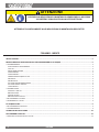 4
4
-
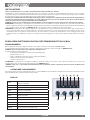 5
5
-
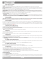 6
6
-
 7
7
-
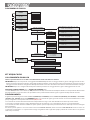 8
8
-
 9
9
-
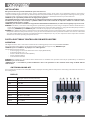 10
10
-
 11
11
-
 12
12
-
 13
13
-
 14
14
-
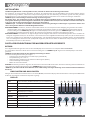 15
15
-
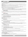 16
16
-
 17
17
-
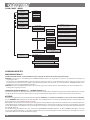 18
18
-
 19
19
-
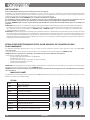 20
20
-
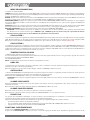 21
21
-
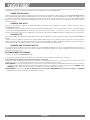 22
22
-
 23
23
-
 24
24
-
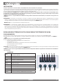 25
25
-
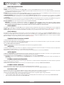 26
26
-
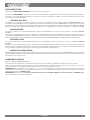 27
27
-
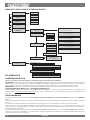 28
28
-
 29
29
-
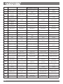 30
30
-
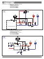 31
31
-
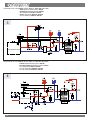 32
32
-
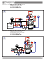 33
33
-
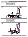 34
34
-
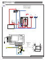 35
35
-
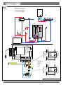 36
36
-
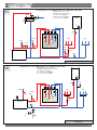 37
37
-
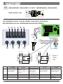 38
38
-
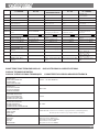 39
39
-
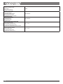 40
40
-
 41
41
-
 42
42
-
 43
43
-
 44
44


La Nordica Assembled and combined ACS Kit 2.0 Manuale del proprietario
- Tipo
- Manuale del proprietario
- Questo manuale è adatto anche per
in altre lingue
- English: La Nordica Assembled and combined ACS Kit 2.0 Owner's manual
- français: La Nordica Assembled and combined ACS Kit 2.0 Le manuel du propriétaire
- español: La Nordica Assembled and combined ACS Kit 2.0 El manual del propietario
- Deutsch: La Nordica Assembled and combined ACS Kit 2.0 Bedienungsanleitung
Documenti correlati
Altri documenti
-
Extraflame Diadema ACS Idro Manuale del proprietario
-
Extraflame Raffaella Idro 2.0 Manuale del proprietario
-
Extraflame Melinda Idro Manuale del proprietario
-
-
-
Extraflame Liliana Idro Manuale del proprietario
-
-
Giacomini R586HPI Istruzioni per l'uso
-
CTX MyPOOL Series Operating
-
MAXA B-Puffroller Manuale del proprietario