STUDIO DUE PL MAX Manuale utente
- Categoria
- Illuminazione di comodità
- Tipo
- Manuale utente
Questo manuale è adatto anche per

User manual for art. 1910 and 19101
Manuale d’uso per art. art. 1910 e 19101
MONOCHROMATIC

rel. 1_10/19 - Studio Due 2
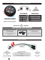
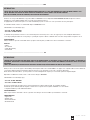
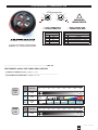
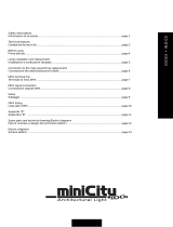
4 PIN connector - Connettore 4 PIN
art. 4 PIN/XLR MF
(OPTIONAL)
INDOOR USE ONLY
!WARNINGIMPORTANTE
art. 4 PIN/XLR MF male/female connectors
(optional)
art. 4 PIN/XLR MF connettori maschio/femmina
(opzionale)
these
CONNECTORS
are for INDOOR use
only
these
CONNECTORS
are IP67
questi connettori sono
solo per uso INTERNO questi connettori
sono IP67
OUTDOOR use, you can make a new
cable utilizing the
art. 4 PIN-CONN M/F
The cable is not endowed with the
connectors kit
Se volete utilizzare gli apparecchi
all’ESTERNO, potete realizzare dei
nuovi cavi con
art. 4 PIN-CONN M/F
Il cavo non è incluso nel kit dei connettori
art. 4 PIN-CONN M/F
optional - opzionale
NUMBER 4 or the GROUND sign.
In questo connettore potete trovare il
NUMERO 4 o il simbolo della TERRA.
!
WARNING
IMPORTANTE
MALEFEMALE
4 or
1
14 or
23
32
4 PIN connectors
** DALI CONNECTION
** CONNESSIONE DALI
* DMX CONNECTION
* CONNESSIONE DMX
DALI CONNECTION
PIN SIGNAL
1 DALI 1
2 DALI 2
3 N.C.
4 N.C.
DMX CONNECTION
PIN SIGNAL
1 GROUND
2N.C.
3 DATA COMPLEMENT (-, inverted)
4 DATA COMPLEMENT (+, not inverted)

rel.1_10/19 - Studio Due
3
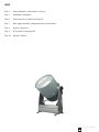
INDEX
Page 4 Safety informations / Informazioni di sicurezza
Page 5 Introduction / Introduzione
Page 6 Technical features / Caratteristiche tecniche
Page 7 Main supply connection / Collegamento fonte di alimentazione
Page 8 Physical / Dimensioni
Page 9 CE standards / Certificazioni CE
Page 10 Warranty / Garanzia

rel. 1_10/19 - Studio Due 4
.................................................................................................................. ENG
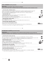
SAFETY INFORMATION (service personnel)
IMPORTANT !
READ ALL CAUTIONS AND WARNINGS PRIOR TO OPERATE THIS EQUIPMENT.
INSTRUCTION TO PREVENT INJURY OR DAMAGE DUE TO ELECTRIC SHOCK, FIRE, MECHANICAL HAZARDS, DANGEROUS MATTERS.
• PROTECTION AGAINST DANGEROUS MATTERS
At the end of its life, must be collected separately. It shouldn’t be thrown as urban waste and neither released in the environment.
It must be collected from the nearest special waste collection point or consigned to your dealer that provides the service.
The incorrect waste disposal can damage the environment and the people for the presence of dangerous substances.
Sanctions are provided for an unauthorized disposal. ............................................................................................................................................................
• PROTECTION AGAINST FIRE
1) Maintain minimum distance of 0,2 meter from walls or any other type flammable surfaces.
2) Maintain minimum distance of 0,2 meter to lighted objects.
3) Replace fuses (if present) only with the specified type and rating.
4) Do not install the fixture close to heat sources. Do not lay the connection cable on the fixture when it is warm.
5) Fixture designed to be installed on normally flammable surfaces. .....................................................................................................................................
• PROTECTION AGAINST ELECTRIC SHOCK
1) This equipment must be earthed.
2) Class I equipment. The power supply cord includes a protective earthing conductor as part of the cord.
3) Disconnect power before servicing (service personnel). ..................................................................................................................................................
• PROTECTION AGAINST MECHANICAL HAZARDS
1) Use secondary safety chain when fixing this equipment.
2) Equipment surface may reach temperature up to 75°C.
3) The protection screens and the lenses must be replaced with genuine parts only if they are visibly damaged and
their effectiveness has been reduced, for example, by cracks or deep scratches. ..............................................................................................................
................................................................................................................... ITA
INFORMAZIONI DI SICUREZZA (personale di servizio)
IMPORTANTE !
LEGGERE ATTENTAMENTE TUTTI GLI AVVERTIMENTI PRIMA DI COMPIERE QUALUNQUE OPERAZIONE SU QUESTO APPARECCHIO.
ISTRUZIONI PER PREVENIRE LESIONI O DANNI DOVUTI AL FUOCO, ALLE SCOSSE ELETTRICHE, AI RISCHI MECCANICI ED A SOSTANZE PERICOLOSE.
•PROTEZIONE CONTRO SOSTANZE PERICOLOSE
A fine vita è oggetto di raccolta separata, non gettare nei comuni cassonetti di rifiuti urbani, né tantomeno nell’ambiente.
Può essere consegnato presso i centri di raccolta delle amministrazioni comunali, oppure presso i rivenditori che forniscono questo servizio.
Lo smaltimento errato può causare danni alle persone e all’ambiente per la possibile presenza di sostanze pericolose.
Sono previste sanzioni in caso di smaltimento abusivo dei suddetti prodotti. ..........................................................................................................................
•PROTEZIONE CONTRO IL FUOCO
1) Mantenere la distanza minima di 0,2 metri da pareti ed altre superfici infiammabili.
2) Mantenere la distanza minima di 0,2 metri dagli oggetti illuminati.
3) Sostituire i fusibili (se presenti) solo con altri dello stesso tipo e valore.
4) Non installare il faro vicino fonti di calore. Non appoggiare il cavo di connessione sul faro quando questo è caldo.
5) Questo apparecchio è adatto per il montaggio su superfici normalmente infiammabili. .......................................................................................................
•PROTEZIONE CONTRO SCOSSE ELETTRICHE
1) Questo apparecchio necessita di messa a terra.
2) Apparecchio di Classe I. Il conduttore di protezione deve far parte del cavo di alimentazione.
3) Disconnettere l’alimentazione prima di aprire l’apparecchio (personale di servizio). ............................................................................................................
•PROTEZIONE CONTRO RISCHI MECCANICI
1) Usare la catena di sicurezza supplementare quando installate l’apparecchio.
2) La temperatura dell’apparecchio può raggiungere 75°C.
3) Gli schermi di protezione e le lenti devono essere sostituiti sempre con ricambi originali se sono visibilmente danneggiati
e se la loro efficacia è stata ridotta, per esempio, da fessure o incisioni profonde. ...............................................................................................................
F
IP65
0,2 m
F
IP65
0,2 m

rel.1_10/19 - Studio Due
5
.................................................................................................................. ENG
INTRODUCTION
CHECK THAT THE FIXTURE HAS NOT BEEN DAMAGED DURING TRANSPORT. IF IT HAS BEEN DAMAGED OR IT DOES NOT WORK, ADDRESS THE
SELLER. WHETHER THE FIXTURE HAS BEEN SHIPPED TO YOU DIRECTLY, PLEASE CONTACT THE SHIPPING COMPANY.
ONLY THE CONSIGNEE (PERSON OR COMPANY) CAN CLAIM FOR THESE DAMAGES.
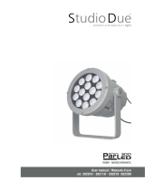
Thanks for choosing our PL MAX fixture, top product within our PIN LIGHT series. Compact IP65 ULTRA NARROW LED SPOT designed for outdoors
installations to create dramatic lighting effects on façades and architectural surfaces.
It equipped with 2,5° ultra-narrow optics for accurate and detailed projection on surfaces to create spectacular effects of great impact.
It’s available in warm, neutral or cool white LEDs. Plug-in or RDM-DALI version.
Standard fixture colour finishing is grey.
• Art. 1910 PL MAX RDM-DALI
• Art. 19101 PL MAX PLUG-IN
To obtain the best performances and for a correct functioning of this unit for the years to come, we suggest you to read carefully this manual before
connecting or putting the fixture into use. By doing so you will gain experience with its commands and connections and you will be easily able to use it.
YOUR REFERENCE
Always remember to give the serial number and to specify the model any time you address the seller for information or assistance.
BASIC KIT
• Fixture
• User manual
• Studio Due warranty
• CE standards
................................................................................................................... ITA
INTRODUZIONE
CONTROLLATE CHE L’APPARECCHIO NON ABBIA SUBITO ALCUN DANNO DURANTE IL TRASPORTO. SE AVESSE SUBITO DEI DANNI O SE NON DOVESSE
FUNZIONARE, RIVOLGETEVI AL VOSTRO RIVENDITORE. SE L’APPARECCHIO VI È STATO SPEDITO DIRETTAMENTE, RIVOLGETEVI SUBITO ALLA DITTA DI
TRASPORTO.
SOLO IL DESTINATARIO (LA PERSONA O DITTA RICEVENTE L’APPARECCHIO) PUÒ RECLAMARE PER QUESTO TIPO DI DANNI.
Grazie per aver scelto il nostro apparecchio PL MAX, prodotto di punta della nostra serie PIN LIGHT. E’ un apparecchio compatto a LED con ottica ultranarrow
con protezione IP65 progettato per installazioni all’aperto ideale per creare effetti di luce su facciate e superfici architettoniche.
Dotato di ottica ultra-narrow da 2,5° per una proiezione accurata e dettagliata sulle superfici per creare effetti spettacolari di grande impatto.
Disponibile con LEDs bianco freddo, neutro o caldo. Versione Plug-in o RDM-DALI.
Standard fixture colour finishing is grey.
• Art. 1910 PL MAX RDM-DALI
• Art. 19101 PL MAX PLUG-IN
Per ottenere il meglio delle prestazioni ed un corretto funzionamento negli anni di questa unità, Vi consigliamo di leggere
attentamente questo manuale prima di collegarla e metterla in uso. In questo modo acquisirete familiarità con i suoi comandi
e collegamenti affinché possiate utilizzarla facilmente.
VOSTRA REFERENZA
Citate sempre il numero del modello e di serie ogni volta che Vi rivolgete al vostro rivenditore per informazioni o assistenza.
CONFEZIONE BASE
• Apparecchio
• Manuale d’uso
• Garanzia Studio Due
• Dichiarazione CE

rel. 1_10/19 - Studio Due 6
.................................................................................................................. ENG / ITA
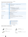
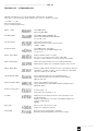
TECHNICAL FEATURES / CARATTERISTICHE TECNICHE
ITEM FIXTURE [ KEY features ]
LEDs Monochromatic 1 NICHIA NVCWL024Z white LED - Expected lifetime: 30.000 hours
Color temperature: 6500K
Max power on LEDs 70W - 62W plug-in version
Total LED lumen emission 4300
Optics 2 x 170mm FRESNEL lenses (2,5°) - On request: Anti-glare
Control (art. 19101) None plug-in version
(art . 1910 ) Standard interface: RS-485, optocoupled input
Protocol: USITT DMX 512 / RDM / DALI DT6
Optional wireless DMX receiver (Wireless Solution)
Connections Main power: Power cable 1.5mt with bare ends
Signal: (art. 19101) None plug-in version
(art . 1910 ) 4 Pin male-Female IP67 connectors
Setup and configuration (art. 19101) None plug-in version
RDM / DRS
DMX or Auto mode with Master-Slave function
Halogen simulation
Ultrafast strobe effect
Electronic smooth dimming
Flicker-free function
DMX channels 3, 1 DMX mode (dimmable version)
Power supply Surge Protection 5KA@8/20uS, 5KV - Voltage range: 200-270VAC; 47-63Hz
Current 0.38A@230V - Active Power Factor: PF>0.95@230V - Inrush current: 60A@230V
Power 80W max - 70W max plug-in version
Physical 278x236,5x375mm
Weight 4,7 Kg
ENVIRONMEN and THERMAL MANAGEMENT
Temperature range, operating: -40°C to 45°C
Temperature range, start-up: -30°C to 45°C
Temperature range, storage: -40°C to 80°C
Thermal protection: thermal switch protection
Metal anti-condensation valve
.................................................................................................................. ENG / ITA
OPTIONAL ACCESSORIES / ACCESSORI OPZIONALI
- art. CLAMP/C
professional aluminium clamp (all fixtures)
_________________________
- art. FFB/C
aluminium fast fixing bracket
- art. WI DMX-REC
wireless on board DMX 512 receiver
_________________________
- art. SAFETY WIRE/C
safety steel cable, black color + plastic protection

rel.1_10/19 - Studio Due
7
.................................................................................................................. ENG / ITA
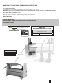
CONNECTION TO THE MAIN POWER / CONNESSIONE ALLA RETE ELETTRICA
This equipment must be earthed.
Class I equipment. The power supply cord includes a protective earthing conductor as part of the cord.
IMPORTANT: to ensure the protection rating of the fixture, in case of replacement of the conductor cable, refer to the CONDUCTOR SIZE TABLE
Questo apparecchio necessita di messa a terra.
Apparecchio di Classe I. Il conduttore di protezione deve far parte del cavo di alimentazione.
IMPORTANTE: per garantire il grado di protezione dell’apparecchio, in caso di sostituzione del cavo di alimentazione, fare riferimento alla TABELLA
SEZIONE CONDUTTORE.
ATTENTION - HIGH VOLTAGE!
ALWAYS DISCONNECT THE MAINS SUPPLY BEFORE ACCESS TO THE CONNECTION AREA.
ATTENZIONE - ALTA TENSIONE!
SCOLLEGARE SEMPRE L’ALIMENTAZIONE PRIMA DI APRIRE IL VANO DEI COLLEGAMENTI.
CONDUCTOR SIZES / SEZIONE CONDUTTORE
(length / lunghezza < 20mt.)
MAINS VOLTAGE CROSS SELECTIONAL AREAS
230V 3X1 mm2 (minimum)
POWER INPUT/
INGRESSO ALIMENTAZIONE ø 6 - 12mm
BROWN / 100/240Vac - 50-60Hz
BLUE / NEUTRAL
GREEN-YELLOW / GROUND
MAIN IN CONNECTION
UNIVERSAL MAIN VOLTAGE
100-240V.~ / 50-60Hz
MAIN IN
Ingresso rete
PIN SIGNAL
(L) Line
(N) Neutral
(G) Ground
PLUG-IN VERSION
DMX VERSION

rel. 1_10/19 - Studio Due 8
example of
label on the rear
of the fixture
DMX IN DMX OUT
.................................................................................................................. ENG / ITA
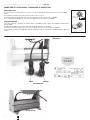
CONNECTION TO THE DMX SIGNAL / CONNESSIONE AL SEGNALE DMX
DMX TERMINAL LINE
The wrong connection of the terminal line or its non-connection are probably the most frequent reasons of the lower DMX
signal.
The terminator is a terminal resistor fitted at the end of the cable. (see pict. 1)
The terminal resistor should have the same value as the impedance of the connection cable (120 Ohm).
It is recommanded that all DMX 512 systems have the terminal resistor fitted in the end of DMX line.
TERMINALE LINEA DMX
L’incorretto o il mancato collegamento del terminale di linea è probabilmente la più comune causa del difettoso funzionamento
della linea DMX.
Il terminale di linea DMX consiste in una resistenza posta alla fine della linea. (vedere fig. 1)
La resistenza terminale dovrebbe avere lo stesso valore dell’impedenza del cavo di collegamento (120 Ohm).
E’ raccomandato per tutti i sistemi DMX 512, di inserire il teminale di linea nel connettore di uscita DMX dell’ultimo apparecchio
collegato.
120 Ohm
Termination resistor
Terminale di linea
Termination resistor
Terminale di linea
120 Ohm
pict. 1
DMX VERSION
PLUG-IN VERSION
4PIN CONNECTORS

rel.1_10/19 - Studio Due
9
DMX
512
DMX
512
8 BIT FUNCTION 0 31 63 95 127 159 191 233 255
CH1 DIMMER
CH2 STROBE
FLASH 0,4Hz / 25Hz
2 -127
OPEN
0 - 1
RAINBOW - FLASH 0,4Hz / 25Hz
128 -255
CH3 LED FADE
TIME
FAST - 0,1 sec.
0 = CUT SLOW
25,5 sec.
LINEAR
8 BIT FUNCTION 0 31 63 95 127 159 191 233 255
CH1 DIMMER
.................................................................................................................. ENG / ITA
DMX CHANNELS and DALI LINE / CANALI DMX e LINEA DALI
- (*) DMX line for Dimmable version. (setting 3ch or 1ch)
--------------------------------------------------------------------------------------------------------------
- (*) linea DMX versione Dimmerabile. (settaggio 3ch o 1ch)
4 PIN connector - Connettore 4 PIN
NUMBER 4 or the GROUND sign.
In questo connettore potete trovare il
NUMERO 4 o il simbolo della TERRA.
!
WARNING
IMPORTANTE
MALEFEMALE
4 or
1
14 or
23
32
4 PIN connectors
** DALI CONNECTION
** CONNESSIONE DALI
* DMX CONNECTION
* CONNESSIONE DMX
DALI CONNECTION
PIN SIGNAL
1 DALI 1
2 DALI 2
3 N.C.
4 N.C.
DMX CONNECTION
PIN SIGNAL
1 GROUND
2N.C.
3 DATA COMPLEMENT (-, inverted)
4 DATA COMPLEMENT (+, not inverted)

rel. 1_10/19 - Studio Due 10
.................................................................................................................. ENG / ITA
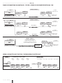
EXAMPLE OF CONNECTION DMX CONTROLLER - FIXTURES / ESEMPIO DI COLLEGAMENTO CENTRALINA - FARI
DMX
fixture 1 fixture 2 fixture 3 fixture 4
TL
NORMAL
Address
set-up 3ch
=C001
Address
set-up 3ch
=C004
Address
set-up 3ch
=C007
Address
set-up 3ch
=C010
fixture 2 fixture 3 fixture 4
TL
MASTER / SLAVE
Set up = MASTER set-up = SLAVE set-up = SLAVE set-up = SLAVE
fixture 1
NORMAL AND MASTER/SLAVE FUNCTIONS / FUNZIONI NORMAL E MASTER/SLAVE
Example 1/ Esempio 1
DMX
Last fixture/
Ultimo apparecchio
Termination resistor/
Terminale di linea
Example 2 / Esempio 2
DMX
line 1 / linea 1
line 2 / linea 2
DMX 1 out DMX 2 out
Connection controller-spot to
1 DMX 512 output over 150 mt. long
Collegamento centralina-spot ad una sola
linea di uscita DMX 512 lunga oltre 150 mt.
LINE > 150 mt. (with microphonic or audio cable)
LINEA > 150 mt. (con cavo microfonico o audio)
DMX
Example 3 / Esempio 3
SIGNAL AMPLIFIER
AMPLIFICATORE
DI SEGNALE
DMX out
DMX out
TL=
Terminal Line
for example fixture set-up at 3 channels
TL
TL
TL
TL
fixture /
apparecchio
fixture /
apparecchio fixture /
apparecchio
fixture /
apparecchio
fixture /
apparecchio
fixture /
apparecchio
fixture /
apparecchio
fixture /
apparecchio
fixture /
apparecchio
fixture /
apparecchio
fixture /
apparecchio
fixture /
apparecchio
fixture /
apparecchio
fixture /
apparecchio fixture /
apparecchio
fixture /
apparecchio
Last fixture/
Ultimo apparecchio
Termination resistor/
Terminale di linea
fixture /
apparecchio
fixture /
apparecchio fixture /
apparecchio
fixture /
apparecchio
Last fixture/
Ultimo apparecchio
Termination resistor/
Terminale di linea
Last fixture/
Ultimo apparecchio
Termination resistor/
Terminale di linea
fixture /
apparecchio fixture /
apparecchio

rel.1_10/19 - Studio Due
11
.................................................................................................................. ENG
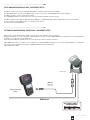
SETUP AND CONFIGURATION BY DRS - DMX REMOTE SETUP
The DRS it’s a new concept of professional LED Lighting fixtures suitable for outdoor permanent installations.
The LED Lighting fixtures can be driven via DMX through a specific electronic device, the DRS DMX Remote Setup, that grant the
possibility to set up the scenarios and the games remotely.
These LED Lighting fixtures have installed on board a series of programs including the stand alone function.
The DRS is a simple set up commander that linked with the DMX input of a LED Lighting fixture allow to program all the functions of the luminaire.
It’s than possible to assign the DMX channel or use the Master/Slave function.
The device is powered through battery.
DRS è il nuovo concetto dell’illuminazione LED per uso professionale nelle installazioni esterne permanenti.
Gli apparecchi LED possono essere controllati e configurati tramite uno specifico controller: il DRS, DMX Remote Setup, il quale consente di programmare e
configurare scene e giochi di luce in modalità remota.
Questi apparecchi LED hanno installati a bordo una serie di giochi che includono la funzione stand alone.
Il DRS, DMX Remote Setup, è un semplice set-up commander che collegato via DMX ad un’apparecchio consente la sua programmazione e configurazione.
E’ possibile assegnare agli apprecchi collegati i canali DMX o utilizzazre la funzione Master/Slave.
Il DRS è alimentato a batterie.
DMX line
XLR - 4pin
connector
MAIN Power
Powered through
battery
RDM CONSOLE
.................................................................................................................. ITA
SETTAGGIO E CONFIGURAZIONE TRAMITE DRS - DMX REMOTE SETUP
example view

rel. 1_10/19 - Studio Due 12
.................................................................................................................. ITA
SETTAGGIO E CONFIGURAZIONE TRAMITE DRS - DMX REMOTE SETUP
Per effettuare la programmazione dei vari parametri di un apparecchio, è necessario procedere come segue:
• Disconnettere l’apparecchio da configurare da altri dispositivi DMX/RDM
• Collegare il cavo DMX dell’apparecchio da configurare, al programmatore DRS
• Accendere il programmatore DRS ed attendere che visualizzi la scritta 8888
• Se il programmatore DRS individua un dispositivo DRS compatibile, visualizza per qualche istante la scritta Conn e,
successivamente, visualizza il nome dell’apparecchio e la relativa versione software
• Se il programmatore DRS non individua alcun dispositivo DRS compatibile o è presente qualche malfunzionamento il display
visualizzerà la scritta SCAn
• Una volta terminata la sequenza di riconoscimento, viene visualizzato il primo menu dell’apparecchio
• I pulsanti UP/DOWN permettono di scorrere la lista dei menu
• Il pulsante ENTER permettere di entrare in un menu o di confermare una opzione in caso di lampeggio del parametro
• Il pulsante ESC annulla una operazione o torna al livello di menu inferiore.
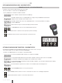
.................................................................................................................. ENG
SETUP AND CONFIGURATION BY DRS - DMX REMOTE SETUP
To make the set-up of the various fixture parameter, proceed as follow:
•Disconnect the fixture to set-up from the other DMX/RDM devices
• Connect the DMX cable of the fixture to the DRS commander
• Switch on the DRS commander and wait for the 8888 sign
• If the DRS commander detects a compatible DRS device, displays shortly the Conn written and afterwards,
displays the name of the fixture and its software version.
• If the DRS commander dont’ detects any compatible DRS device or is present any malfunction, the display
shows the SCAn written
• When the detection sequence is finished, the display shows the first menu
• The UP/DOWN buttons allow to scroll forward/backward the menu list
• The ENTER button allow to confirm the selected option (if the parameter is flashing)
• The ESC button allow to delete the operation and return to a previus menu level
dimmable version only / solo versione dimmerabile

rel.1_10/19 - Studio Due
13
.................................................................................................................. ENG / ITA
DRS MENU’ LIST / ELENCO MENU DRS
Switching on the fixture you can see the model and the software version. For example:
All’accensione, viene visualizzato il modello di apparecchio e la versione software. Per esempio:
--> PL Max --> 1_00
than it’s shown the fist menu
poi viene visualizzato il primo menu
Address (Addr) Set the DMX address
Imposta l’indirizzo DMX
Auto Mode (ModE) Set the DMX, SLAVE or MASTER mode
Imposta la modalità DMX, SLAVE o MASTER
(no, SL, Pr01…Prxx)
Auto Speed (PrSP) Set the preset execution speed
Imposta la velocità di esecuzione dei giochi interni
( -400%…+400%)
N. Channels (nChn) Set the DMX channels of the fixture
Imposta il numero di canali DMX dell’apparecchio
(13, 10, 6, 3 etc.)
Wireless enable (ULEn) Enable or disable the wireless reception
Consente o non consente la ricezione wireless (ON / OFF)
The cable reception is disabled / La ricezione via cavo viene disabilita
Wireless unlink (ULPA) Remove the link from the fixture to the associated transmitter (PA?)
Elimina il link tra l’apparecchio e il trasmettitore al quale è stato associato
Wireless bridge (ULbr) If wireless is ON, enable the transmission of the received data by cable to the
other fixtures / Se il wireless è attivo, consente la trasmissione dati agli altri
apprecchi collegati via cavo. (ON / OFF)
Smooth Dimming (SMth) Set the interpolation type for the smooth dimming function
Imposta il tipo di interpolazione per la funzione smooth dimming
(OFF, Sd1, Sd2, Sd3)
Halogen Simulation (HALS) Set the alogen simulation function mode
Imposta il funzionamento della modalità simulazione lampada alogena
(OFF, Mod1, Mod2)
Flicker free function (FLcr)
Select the value f1 .. f2
Selezionate il valore desidarato f1 .. f2
Test (tESt) Enables the test of the fixture and execute a factory program to check
the right functioning
Abilita il test dell’apparecchio ed esegue un programma di fabbrica per
verificarne il funzionamento
(OFF, On)
Reset (rSEt) Execute a reset of the electronic section
Esegue un reset della parte elettronica
Format (FrMt) Restore the factory setting (Require confirmation)
Ripristina le impostazioni di fabbrica (Viene chiesta conferma)

rel. 1_10/19 - Studio Due 14
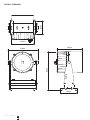
PHYSICAL / DIMENSIONI
236,50
375,00
135,00
214,00
160,00
278,00

rel.1_10/19 - Studio Due
15
è conforme alle norme:
is in conformity with the standard:
e quindi ai requisiti essenziali delle Direttive:
and therefore according to essential requirement of Directives:
EN 61000-4-2
EN 61000-4-3
EN 61000-4-4
EN 61000-4-5
EN 61000-4-6
EN 61000-4-11
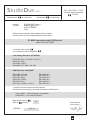
2004/108/EC – Electromagnetic compatibility
2006/95/EC – Low Voltage directive
ECM Directive: 2014/30/EU
EN 61000-3-2:2014
EN 61000-3-3:2013
EN 61547:2009
EN 55103-2:2009
EN 55015:2013
EN 55103-1:2009 + A1:2012
Low Voltage Directive: 2014/35/EU
EN 60529:1991 + A1:2000 + A2:2013
EN 62471:2008
EN 60598-1:2015
EN 60598-2-17:1989 + A2:1991
La ditta:
The firm:
dichiara sotto la propria responsabilità che il prodotto:
declare under our sole responsability that the product:
PL MAX (monochromatic) IP65 series
code 1910 and 19101
VITERBO, 10/07/19
19
Data di apposizione :
Date of marking :
Doc. 1910 REV 2 - 07/19
PL MAX (Monochormatic)
07/2019
STUDIO DUE light s.r.l.
Strada Poggino, 100
01100 VITERBO
ITALY
Dichiarazione di conformità Declaration of conformity
StudioDue
light s.r.l.
PAOLO SENSI
General Manager

rel. 1_10/19 - Studio Due 16
Warranty CARD
WARRANTY / GARANZIA
Company name: ................................................................................................................................
Mr./Mrs./Miss: ..................................................................................................................................
Address: ............................................................................................................................................
Tel. or E-mail : ..................................................................................................................................
Dealer: .............................................................................................
SALE CONDITIONS
1) Price quoted are not inclusive of lamp and package.
Package charge is 2% on the net price for all the items.
These prices should be subject to possible variations for eventual rises of production costs or duties.
Claims for possible damages during the freight, must be notified to the carrier.
Any claim must be notified within 8 days from the recept of the goods.
The buyer is responsable of the right installation and use of the apparatus.
All the apparatuses are guaranteed for one year against defects of manifacture or materials.
Defects and breakeges caused by wrong connection or use of the apparatuses are not subject to guarantee.
The lamp is excluded from the warranty.
For any dispute is competent the Tribunal of Viterbo.
CONDIZIONI DI VENDITA
1) I prezzi riportati sono esclusi di IVA, lampada ed imballaggio.
Il costo di imballaggio è del 2% sul prezzo netto per tutti gli articoli.
Detti prezzi possono essere soggetti a possibili variazioni per eventuali aumenti dei costi di produzione o imposte.
La merce viaggia a rischio e pericolo del committente, anche se in porto franco.
Reclami per possibili danni durante il trasporto, dovranno essere fatti esclusivamente al vettore.
Eventuali osservazioni sulle merci ricevute dovranno esserci notificate entro e non oltre 8 giorni dal ricevimento delle medesime. Sui ritardi dei pagamenti
verrà conteggiato l’interesse commerciale.
L’acquirente si impegna a comunicare la propria esatta ragione sociale e partita IVA al momento dell’ordine e sotto la propria responsabilità di verificarla in
fattura.
L’acquirente è responsabile della corretta installazione ed uso delle apparecchiature.
Tutte le apparecchiature godono della garanzia di un anno contro difetti di fabbricazione o di materiali, sono esclusi dalla garanzia danni derivanti da un cattivo
uso o installazione delle apparecchiature.
Le lampade restano comunque escluse dalla garanzia.
Per ogni controversia è competente il Foro di Viterbo.

rel.1_10/19 - Studio Due
17
this page is intentionally left blank / questa pagina è stata lasciata intenzionalmente bianca

rel. 1_10/19 - Studio Due 18
this page is intentionally left blank / questa pagina è stata lasciata intenzionalmente bianca

rel.1_10/19 - Studio Due
19
this page is intentionally left blank / questa pagina è stata lasciata intenzionalmente bianca

Studio Due - ©
The features on this brochure are not binding: they can be changed without notice.
Le caratteristiche riportate su questo catalogo non sono impegnative: possono essere soggette a variazioni senza preavviso.
Head Office: STUDIO DUE s.r.l. (I)
Str. Poggino, 100 - 01100 Viterbo (Italy)
tel. +39.0761.352520
fax +39.0761.352653
www.studiodue.com
for technical info
STUDIO DUE (UK)
3 Encon Court Owl Close
Moulton Park Industrial Estate
Northampton England UK - NN3 6 HZ
tel. +44.1933.650.820
-
 1
1
-
 2
2
-
 3
3
-
 4
4
-
 5
5
-
 6
6
-
 7
7
-
 8
8
-
 9
9
-
 10
10
-
 11
11
-
 12
12
-
 13
13
-
 14
14
-
 15
15
-
 16
16
-
 17
17
-
 18
18
-
 19
19
-
 20
20


STUDIO DUE PL MAX Manuale utente
- Categoria
- Illuminazione di comodità
- Tipo
- Manuale utente
- Questo manuale è adatto anche per
in altre lingue
- English: STUDIO DUE PL MAX User manual
Documenti correlati
-
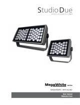 STUDIO DUE MEGAWHITE 66 M DALI Manuale utente
-
 STUDIO DUE PARLED 300 PRO RGBW IP20 Manuale utente
-
 STUDIO DUE Easy Color 12.P Manuale utente
-
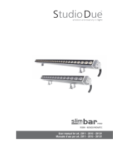
 STUDIO DUE SLIMBAR FLAT RGBW 50cm Manuale utente
-
 STUDIO DUE COMPACTBAR RGBW 100cm Manuale utente
-
 STUDIO DUE SLIMBAR PLUS POB W 100 cm Manuale utente
-
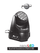 STUDIO DUE nanoLED User's And Operator's Manual
-
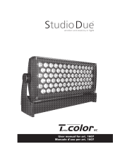 STUDIO DUE T-COLOR 6C RGBWA+UV Manuale utente
-
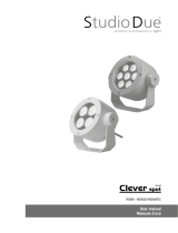 STUDIO DUE CLEVER SPOT RGBW Manuale utente
-
 STUDIO DUE CITYBEAM LED SL84 RGBW Manuale utente


Altri documenti
-
 STUDIODUE 0303 Manuale del proprietario
-
CAME OH/DALI DMX Guida d'installazione
-
Griven Parade L MC 2 Recessed RGBW Manuale del proprietario
-
-
-
Griven Moon wall Dynamic White Manuale del proprietario
-
-
-
ProLights 91x3 W RGB + lime high power Full Colour LED ellipsoidal Manuale utente
-
iGuzzini UB61 Guida d'installazione
