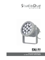
STUDIO DUE PARLED 300 PRO RGBW IP20 Manuale utente
- Categoria
- Illuminazione di comodità
- Tipo
- Manuale utente

User manual / Manuale d’uso
art. 202010 - 202110 - 202210 -202200
RGBW - MONOCHROMATIC

!
WARNING
IMPORTANTE
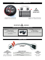
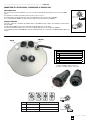
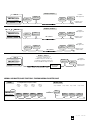
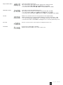
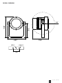
4 PIN connector - Connettore 4 PIN
NIP SIGNAL
1GROUND/RETURN/OV
N.C.
2
DATA COMPLEMENT ( -, INVERTED)
3
4 or DATATRUE ( +, NON INVERTED)
MALEFEMALE
4 or 1
14 or
23
32
4 PIN connectors
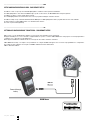
art. 4 PIN/XLR MF
(OPTIONAL)
INDOOR USE ONLY
!WARNINGIMPORTANTE
art. 4 PIN/XLR MF male/female connectors
(optional)
art. 4 PIN/XLR MF connettori maschio/femmina
(opzionale)
these
CONNECTORS
are for INDOOR use
only
these
CONNECTORS
are IP67
questi connettori sono
solo per uso INTERNO questi connettori
sono IP67
,I\RXZDQWWRFRQQHFWWKH¿[WXUHVIRU
OUTDOOR use, you can make a new
cable utilizing the
art. 4 PIN-CONN M/F
The cable is not endowed with the
connectors kit
Se volete utilizzare gli apparecchi
all’ESTERNO, potete realizzare dei
nuovi cavi con
art. 4 PIN-CONN M/F
Il cavo non è incluso nel kit dei connettori
art. 4 PIN-CONN M/F
HQGRZHGZLWKWKH¿[WXUHLQFOXVRQHOO¶DSSDUHFFKLR
RSWLRQDORS]LRQDOH
,QWKLVFRQQHFWRU\RXFDQ¿QGWKH
NUMBER 4 or the GROUND sign. In questo connettore potete trovare il
NUMERO 4 o il simbolo della TERRA.

rel.2_06/23 - Studio Due
3
INDEX
Page 4 Safety informations / Informazioni di sicurezza
Page 5 Introduction / Introduzione
Page 6 Technical features / Caratteristiche tecniche
Page 8 Main supply connection / Collegamento fonte di alimentazione
Page 9 DMX connections / Connessioni DMX
Page 10 Example of connections DMX-Controller / Esempi di collegamento DMX-Controller
Page 11 Setup and configuration (touch control panel) / Configurazione e settaggio (pannello di controllo touch)
Page 15 DMX Channels list / Lista canali DMX
Page 18 Physical / Dimensioni
Page 19 Warranty / Garanzia
Page 20 CE standards / Certificazioni CE

rel. 2_06/23 - Studio Due 4
.................................................................................................................. ENG
SAFETY INFORMATION (service personnel)
IMPORTANT !
READ ALL CAUTIONS AND WARNINGS PRIOR TO OPERATE THIS EQUIPMENT.
INSTRUCTION TO PREVENT INJURY OR DAMAGE DUE TO ELECTRIC SHOCK, FIRE, MECHANICAL HAZARDS, DANGEROUS MATTERS.
• PROTECTION AGAINST DANGEROUS MATTERS
At the end of its life, must be collected separately. It shouldn’t be thrown as urban waste and neither released in the environment.
It must be collected from the nearest special waste collection point or consigned to your dealer that provides the service.
The incorrect waste disposal can damage the environment and the people for the presence of dangerous substances.
Sanctions are provided for an unauthorized disposal. ............................................................................................................................................................
• PROTECTION AGAINST FIRE
1) Maintain minimum distance of 0,2 meter to lighted objects.
2) Replace fuses (if present) only with the specified type and rating.
3) Do not install the fixture close to heat sources. Do not lay the connection cable on the fixture when it is warm.
4) Fixture designed to be installed on normally flammable surfaces. .....................................................................................................................................
• PROTECTION AGAINST ELECTRIC SHOCK
1) This equipment must be earthed.
2) Class I equipment. The power supply cord includes a protective earthing conductor as part of the cord.
3) Disconnect power before servicing (service personnel).
4) To replace the LEDs, contact: Studio Due Srls.
5) If the external flexible cable of this appliance is damaged, it must only be replaced by the manufacturer,
its assistance service, or equivalent qualified personnel, in order to avoid dangers. ...........................................................................................................
• PROTECTION AGAINST MECHANICAL HAZARDS
1) Use secondary safety chain when fixing this equipment.
2) The protection screens and the lenses must be replaced with genuine parts only if they are visibly damaged and
their effectiveness has been reduced, for example, by cracks or deep scratches.
3) Do not look directly into the illuminated LEDs of the product for long periods of time. LED lamps can cause eye
damage or irritation. Do not look directly into the light source using an optical instrument that focuses on the light beams.
The device should be positioned so that there is no prolonged observation of the device at a distance of less than 100cm. (RG1 – IEC/TR 62778:2014).
................................................................................................................... ITA
INFORMAZIONI DI SICUREZZA (personale di servizio)
IMPORTANTE !
LEGGERE ATTENTAMENTE TUTTI GLI AVVERTIMENTI PRIMA DI COMPIERE QUALUNQUE OPERAZIONE SU QUESTO APPARECCHIO.
ISTRUZIONI PER PREVENIRE LESIONI O DANNI DOVUTI AL FUOCO, ALLE SCOSSE ELETTRICHE, AI RISCHI MECCANICI ED A SOSTANZE PERICOLOSE.
•PROTEZIONE CONTRO SOSTANZE PERICOLOSE
A fine vita è oggetto di raccolta separata, non gettare nei comuni cassonetti di rifiuti urbani, né tantomeno nell’ambiente.
Può essere consegnato presso i centri di raccolta delle amministrazioni comunali, oppure presso i rivenditori che forniscono questo servizio.
Lo smaltimento errato può causare danni alle persone e all’ambiente per la possibile presenza di sostanze pericolose.
Sono previste sanzioni in caso di smaltimento abusivo dei suddetti prodotti. ..........................................................................................................................
•PROTEZIONE CONTRO IL FUOCO
1) Mantenere la distanza minima di 0,2 metri dagli oggetti illuminati.
2) Sostituire i fusibili (se presenti) solo con altri dello stesso tipo e valore.
3) Non installare il faro vicino fonti di calore. Non appoggiare il cavo di connessione sul faro quando questo è caldo.
4) Questo apparecchio è adatto per il montaggio su superfici normalmente infiammabili. .......................................................................................................
•PROTEZIONE CONTRO SCOSSE ELETTRICHE
1) Questo apparecchio necessita di messa a terra.
2) Apparecchio di Classe I. Il conduttore di protezione deve far parte del cavo di alimentazione.
3) Disconnettere l’alimentazione prima di aprire l’apparecchio (personale di servizio).
4) Per la sostituzione dei LED contattare l’azienda: Studio Due Srls
5) Se il cavo flessibile esterno di questo apparecchio è danneggiato, deve essere sostituito esclusivamente
dal costruttore, dal suo servizio di assistenza, o da personale qualificato equivalente, al fine di evitare pericoli. .................................................................
•PROTEZIONE CONTRO RISCHI MECCANICI
1) Usare la catena di sicurezza supplementare quando installate l’apparecchio.
2) Gli schermi di protezione e le lenti devono essere sostituiti sempre con ricambi originali se sono visibilmente danneggiati
e se la loro efficacia è stata ridotta, per esempio, da fessure o incisioni profonde.
3) Non guardare direttamente nei LED illuminati del prodotto per lunghi periodi di tempo. Le lampade a LED possono
causare danni o irritazione agli occhi. Non guardare direttamente nella sorgente luminosa utilizzando uno strumento
ottico che si concentra sui fasci di luce. L’apparecchio dovrebbe essere posizionato in modo che non sia prevista
un’osservazione prolungata dell’apparecchio ad una distanza inferiore di 100cm. (RG1 – IEC/TR 62778:2014).

rel.2_06/23 - Studio Due
5
.................................................................................................................. ENG
INTRODUCTION
CHECK THAT THE FIXTURE HAS NOT BEEN DAMAGED DURING TRANSPORT. IF IT HAS BEEN DAMAGED OR IT DOES NOT WORK, ADDRESS THE
SELLER. WHETHER THE FIXTURE HAS BEEN SHIPPED TO YOU DIRECTLY, PLEASE CONTACT THE SHIPPING COMPANY.
ONLY THE CONSIGNEE (PERSON OR COMPANY) CAN CLAIM FOR THESE DAMAGES.
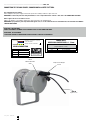
Thank you for choosing one of the PARLED300 series appliances, our compact IP67 SPOT projector. Suitable for permanent architectural installations, is
flexible for mounting on poles, walls or on the ground.
RDM control and configuration. Integral Wireless DMX control is available as an option (art. WI PCB-REC).
• Standard fixture colour finishing is grey.
• Art. 202010 PARLED 300PRO DRS RDM IP67 (RGBW)
• Art. 202110 PARLED 300PRO RDM IP20 (RGBW)
• Art. 202210 PARLED 300PRO/M DRS RDM IP67 (monochromatic)
• Art. 202200 PARLED 300PRO/M PLUG-IN IP67 (monochromatic)
To obtain the best performances and for a correct functioning of this unit for the years to come, we suggest you to read carefully this manual before
connecting or putting the fixture into use. By doing so you will gain experience with its commands and connections and you will be easily able to use it.
YOUR REFERENCE
Always remember to give the serial number and to specify the model any time you address the seller for information or assistance.
BASIC KIT
• Fixture
• Main power 1.5mt 3x1 cable (for IP67 articles)
• IN-OUT DMX IP67 4pin connectors (for IP67 articles)
• MAIN IN POWERCON connector IP20 (for it. 202110)
• User manual
• Studio Due warranty
• CE standards
................................................................................................................... ITA
INTRODUZIONE
CONTROLLATE CHE L’APPARECCHIO NON ABBIA SUBITO ALCUN DANNO DURANTE IL TRASPORTO. SE AVESSE SUBITO DEI DANNI O SE NON DOVESSE
FUNZIONARE, RIVOLGETEVI AL VOSTRO RIVENDITORE. SE L’APPARECCHIO VI È STATO SPEDITO DIRETTAMENTE, RIVOLGETEVI SUBITO ALLA DITTA DI
TRASPORTO.
SOLO IL DESTINATARIO (LA PERSONA O DITTA RICEVENTE L’APPARECCHIO) PUÒ RECLAMARE PER QUESTO TIPO DI DANNI.
Grazie per aver scelto uno degli apparecchi della serie PARLED300, il nostro proiettorecompatto IP67 SPOT LIGHT. Adatto per installazioni architettoniche
permanenti, è ideale per il montaggio su pali, pareti o sul terreno.
Controllo e configurazione RDM. Il controllo DMX wireless integrato è disponibile come opzione (art. WI PCB-REC).
• Finitura standard colore grigio.
• Art. 202010 PARLED 300 PRO DRS RDM IP67 (RGBW)
• Art. 202110 PARLED 300 PRO RDM IP20 (RGBW)
• Art. 202210 PARLED 300 PRO DRS RDM M IP67 (monochromatic)
• Art. 202200 PARLED 300 PRO PLUG-IN M IP67 (monochromatic)
Per ottenere il meglio delle prestazioni ed un corretto funzionamento negli anni di questa unità, Vi consigliamo di leggere attentamente questo manuale
prima di collegarla e metterla in uso. In questo modo acquisirete familiarità con i suoi comandi e collegamenti affinché possiate utilizzarla facilmente.
VOSTRA REFERENZA
Citate sempre il numero del modello e di serie ogni volta che Vi rivolgete al vostro rivenditore per informazioni o assistenza.
CONFEZIONE BASE
• Apparecchio
• Cavo di rete 1.5mt 3x1 (per articoli IP67)
• Connettori IP67 IN-OUT DMX 4pin (per articoli IP67)
• Connettore MAIN IN POWERCON IP20 (per art. 202110)
• Manuale d’uso
• Garanzia Studio Due
• Dichiarazione CE

rel. 2_06/23 - Studio Due 6
.................................................................................................................. ENG / ITA
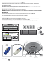
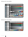
TECHNICAL FEATURES / CARATTERISTICHE TECNICHE
PARLED300 PRO DRS RGBW IP67 (it. 202010)
.................................................................................................................. ENG / ITA
OPTIONAL ACCESSORIES / ACCESSORI OPZIONALI
- Barn-door
- Wireless DMX receiver
0& ,1 (2
1+34 / ( 55, ,1 (2
* "/3 5
+3$ -7 895
6 "+3$ "3 95
$ "+3$ "3 5
"+ "+3$ "3
"+3$ "3 5
$ 8:
:*:
5:
5:
(:
:
)" 1$
/ :
/ :
/8:*:
!$$# $6 #4" -$ ; *33 #4" 5 <53
-7 %$"; (&$ #$$# 3",/3"
!$" 0& #" =.. -75 , -
#" =.. -75 , - > " $ ?+
)+$#$ 6#6 -7 # $$" / 4"$# /3 92 2
-7 + -6 -,"@ /+$#$
$""%$ 3&+ #$"
!$$++ 633$% ,A
3 633$% /+$#$
"%$ 3+"$
!B- 3+"$
)"#C,/ /+$#$
+& -E
-7 # $$" 9# , # , 5# , (#
$&+ $% , D!F (E G
5
!+$ <5HD!
)# )I<95HD!
$+ #+$ 5HD
." :
&#$ $%
&$% 3&+ ,:! >(5:!
G " * & * 33 (*9*33
% 2% (< 2%
-" =" #" (33 3&6 %"
-- "$
"" "+3$+3 ""0
"0 &6 #6
-+$$% 03 +/#
.+ &$"
!"+ /$ $% 0 9 $66
-$ 6 3$ 1$
B

rel.2_06/23 - Studio Due
7
*$ +, "-
,&.% ) "//+ +, "-
0$1 ). /
&. 23 45/
1 &. . 5/
&. . /
& &. . 6
&. . /
47
/7
/7 0 7
/7
"7
67
8 ,
)67
)7
)47067
# 1 % 2 9 # 6/ .+).
23 ! 9 3/$ .+).
# *$ :('' 23/ + 2
:('' 23/ + 2 ; <&
8& 11 23 ) % ). 5--
23 & 21 2+(= )&
! .$&
# && 1.. ! +>
(. 1.. ! )&
! .&
#?2 .&
8@+) )&
(&$ 2D( ; $& %& $
23 5 + 6 + / + "
$& ! + CC B#E "CD6 F
/
#& A/GB#
8 8HA5/GB#
& & /GB
' 67
$ !
$ ! .$& +7# ;"/7#
(F 0 $ 0 .. "C050..
! -! "A6 -!
2 : ".. .$1 !
22
&. &. *
* $1 1
2& ! *. (&)
'& $
#& ) ! * 56 11
2 1 . ,
?
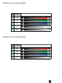
.................................................................................................................. ENG / ITA
TECHNICAL FEATURES / CARATTERISTICHE TECNICHE
PARLED 300 PRO RGBW IP20 (it. 202110)
.................................................................................................................. ENG / ITA
OPTIONAL ACCESSORIES / ACCESSORI OPZIONALI
- Barn-door
- Wireless DMX receiver

rel. 2_06/23 - Studio Due 8
WW W
warm neutral cool
BGR A
.................................................................................................................. ENG / ITA
TECHNICAL FEATURES / CARATTERISTICHE TECNICHE
PARLED 300 PRO M (it. 202210)
/ '0!,# 1
'0!,$ 1
'0!,2 1
%&3 . $ %!40!%5$$$
6 7 . 2
& 8
$9
:9
29
29
$9
"9
; %
."9
.9
.$96"9
4 7 3 < 6 3 02 =2
8 < $ !"# *.
4 / (-!,, 82 *
(-!,, 82 * >' ?&
;& 8 & 7 *-+ .&
! &
4&& 7 *@
- 7 .&
0 &
;A *. .&
- & B-
8 *
!& * ## 54C $#B" 0D
' E
4& =$F5
; ;G=E2F54
, "9
! !"#
& *94 >$294
-D 6 6 $#6E6
' 1 $=" 1
( $ 7
&& /
/ 7 7
& / -&.
,&
4& . ) / E" 77
)7 %
H
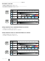
.................................................................................................................. ENG / ITA
OPTIONAL ACCESSORIES / ACCESSORI OPZIONALI
- Barn-door
- Wireless DMX receiver

rel.2_06/23 - Studio Due
9
.................................................................................................................. ENG / ITA
OPTIONAL ACCESSORIES / ACCESSORI OPZIONALI
- Barn-door
- Wireless DMX receiver
WW W
warm neutral cool
BGR A
.................................................................................................................. ENG / ITA
TECHNICAL FEATURES / CARATTERISTICHE TECNICHE
PARLED 300 PLUG-IN M (art. 202200)
" #$% &
#$' &
#$( &
)*+ ! ,-'.$/'-''
01 * , (
)* 2-
,, '3
43
-(3
-(3 0 3
(3
'3
53
6, !
53
-3
'3053
.!!, 1 +, !78 0-** + $( -9(*
.!! " ):
) : - %% /.; '%<5 $=
!7 # >
.) 9'?/
!7 6! 6@9>(?/.
53
!! : 5%
A: *) 3. B'(3.
=, 0 0 ** '%0->0**
#: &:, '95 &:
, '** *1 :,,
,,
)*)* !"
!", !71 !1
!): ,",*, )
),, !!
.!!) ,: " >5 ,11
1 * !
D,

rel. 2_06/23 - Studio Due 10
.................................................................................................................. ENG / ITA
CONNECTION TO THE MAIN POWER / CONNESSIONE ALLA RETE ELETTRICA
This equipment must be earthed.
Class I equipment. The power supply cord includes a protective earthing conductor as part of the cord.
IMPORTANT: to ensure the protection rating of the fixture, in case of replacement of the conductor cable, refer to the CONDUCTOR SIZE TABLE
Questo apparecchio necessita di messa a terra.
Apparecchio di Classe I. Il conduttore di protezione deve far parte del cavo di alimentazione.
IMPORTANTE: per garantire il grado di protezione dell’apparecchio, in caso di sostituzione del cavo di alimentazione, fare riferimento alla TABELLA
SEZIONE CONDUTTORE.
ATTENTION - HIGH VOLTAGE!
ALWAYS DISCONNECT THE MAINS SUPPLY BEFORE ACCESS TO THE CONNECTION AREA.
ATTENZIONE - ALTA TENSIONE!
SCOLLEGARE SEMPRE L’ALIMENTAZIONE PRIMA DI APRIRE IL VANO DEI COLLEGAMENTI.
CONDUCTOR SIZES / SEZIONE CONDUTTORE
(length / lunghezza < 20mt.)
MAINS VOLTAGE CROSS SELECTIONAL AREAS
230V 3X1 mm2 (minimum)
POWER INPUT/
INGRESSO ALIMENTAZIONE ø 6 - 12mm
MAIN IN
Ingresso rete
BROWN / 100/277Vac - 50-60Hz
BLUE / NEUTRAL
GREEN-YELLOW / GROUND
MAIN IN CONNECTION
UNIVERSAL MAIN VOLTAGE
100-277V~ / 50-60Hz
PIN SIGNAL
(L) Line
(N) Neutral
(G) Ground
Metal
Anti-Condensation
Valve Not present in Plug-in
version

rel.2_06/23 - Studio Due
11
DMX IN
.................................................................................................................. ENG / ITA
CONNECTION TO THE DMX SIGNAL / CONNESSIONE AL SEGNALE DMX
DMX TERMINAL LINE
The wrong connection of the terminal line or its non-connection are probably the most frequent reasons of the lower DMX
signal.
The terminator is a terminal resistor fitted at the end of the cable. (see pict. 1)
The terminal resistor should have the same value as the impedance of the connection cable (120 Ohm).
It is recommanded that all DMX 512 systems have the terminal resistor fitted in the end of DMX line.
TERMINALE LINEA DMX
L’incorretto o il mancato collegamento del terminale di linea è probabilmente la più comune causa del difettoso funzionamento
della linea DMX.
Il terminale di linea DMX consiste in una resistenza posta alla fine della linea. (vedere fig. 1)
La resistenza terminale dovrebbe avere lo stesso valore dell’impedenza del cavo di collegamento (120 Ohm).
E’ raccomandato per tutti i sistemi DMX 512, di inserire il teminale di linea nel connettore di uscita DMX dell’ultimo apparecchio
collegato.
120 Ohm
Termination resistor
Terminale di linea
Termination resistor
Terminale di linea
120 Ohm
pict. 1
PIN
1SHIELD GROUND/RETURN/OV
2)DETREVNI,-(TNEMELPMOCATADROTCUDNOCRENNI
3 INNER CONDUCTOR DATA TRUE ( +, NON INVERTED)
DMX inputDMX output Termination resistor
Terminale di linea
120 Ohm
DMX inputDMX output
120 Ohm
Termination resistor
Terminale di linea
1
2
3
4
Female and Male 4 PIN connector /
Connettore 4 PIN femmina e maschio
DMX OUT
DMX CONNECTION
PIN SIGNAL
1GROUND
2N.C.
3DATA COMPLEMENT (-, inverted)
4DATA COMPLEMENT (+, not inverted)

rel. 2_06/23 - Studio Due 12
MAIN IN
Ingresso rete
MAIN OUT
Uscita rete
DMX INDMX OUT
.................................................................................................................. ENG / ITA
CONNECTION TO THE MAIN POWER and DMX SIGNAL / CONNESSIONE ALLA RETE ELETTRICA e SEGNALE DMX
This equipment must be earthed.
Class I equipment. The power supply cord includes a protective earthing conductor as part of the cord.
IMPORTANT: to ensure the protection rating of the fixture, in case of replacement of the conductor cable, refer to the CONDUCTOR SIZE TABLE
Questo apparecchio necessita di messa a terra.
Apparecchio di Classe I. Il conduttore di protezione deve far parte del cavo di alimentazione.
IMPORTANTE: per garantire il grado di protezione dell’apparecchio, in caso di sostituzione del cavo di alimentazione, fare riferimento alla TABELLA
SEZIONE CONDUTTORE.
DMX TERMINAL LINE
The wrong connection of the terminal line or its non-connection are probably the most frequent reasons of the lower DMX signal.
The terminator is a terminal resistor fitted at the end of the cable. (see pict. 1)
The terminal resistor should have the same value as the impedance of the connection cable (120 Ohm).
It is recommanded that all DMX 512 systems have the terminal resistor fitted in the end of DMX line.
TERMINALE LINEA DMX
L’incorretto o il mancato collegamento del terminale di linea è probabilmente la più comune causa del difettoso funzionamento della linea DMX.
Il terminale di linea DMX consiste in una resistenza posta alla fine della linea. (vedere fig. 1)
La resistenza terminale dovrebbe avere lo stesso valore dell’impedenza del cavo di collegamento (120 Ohm).
E’ raccomandato per tutti i sistemi DMX 512, di inserire il teminale di linea nel connettore di uscita DMX dell’ultimo apparecchio collegato.
CONDUCTOR SIZES / SEZIONE CONDUTTORE
(length / lunghezza < 20mt.)
MAINS VOLTAGE CROSS SELECTIONAL AREAS
230V 3X1 mm2 (minimum)
POWER INPUT/
INGRESSO ALIMENTAZIONE ø 6 - 12mm
BROWN / 100/277Vac - 50-60Hz
BLUE / NEUTRAL
GREEN-YELLOW / GROUND
MAIN IN CONNECTION
UNIVERSAL MAIN VOLTAGE
100-277V~ / 50-60Hz
PIN SIGNAL
(L) Line
(N) Neutral
(G) Ground
PIN
1SHIELD GROUND/RETURN/OV
2)DETREVNI,-(TNEMELPMOCATADROTCUDNOCRENNI
3 INNER CONDUCTOR DATATRUE ( +, NON INVERTED)
DMX inputDMX output
Termination resistor
Terminale di linea
120 Ohm
DMX inputDMX output
120 Ohm
Termination resistor
Terminale di linea
MAIN OUT POWERCON
connector
(optional)
MAIN IN POWERCON
connector
(included)

rel.2_06/23 - Studio Due
13
DMX-RDM console
fixture 1 fixture 2 fixture 3 fixture 4
TL
NORMAL
Address
set-up 4ch
=C001
Address
set-up 4ch
=C005
Address
set-up 4ch
=C009
Address
set-up 4ch
=C013
fixture 2 fixture 3 fixture 4
TL
MASTER / SLAVE
Set up = MASTER set-up = SLAVE set-up = SLAVE set-up = SLAVE
fixture 1
NORMAL AND MASTER/SLAVE FUNCTIONS / FUNZIONI NORMAL E MASTER/SLAVE
Example 1/ Esempio 1
DMX-RDM console
Last fixture/
Ultimo apparecchio
Termination resistor/
Terminale di linea
Example 2 / Esempio 2
DMX-RDM console
line 1 / linea 1
line 2 / linea 2
DMX 1 out DMX 2 out
Connection controller-spot to
1 DMX 512 output over 150 mt. long
Collegamento centralina-spot ad una sola
linea di uscita DMX 512 lunga oltre 150 mt.
LINE > 150 mt. (with microphonic or audio cable)
LINEA > 150 mt. (con cavo microfonico o audio)
DMX-RDM console
Example 3 / Esempio 3
SIGNAL AMPLIFIER
AMPLIFICATORE
DI SEGNALE
DMX out
DMX out
TL=
Terminal Line
for example fixture set-up at 4 channels
TL
TL
TL
TL
fixture /
apparecchio
fixture /
apparecchio fixture /
apparecchio
fixture /
apparecchio
fixture /
apparecchio
fixture /
apparecchio
fixture /
apparecchio
fixture /
apparecchio
fixture /
apparecchio
fixture /
apparecchio
fixture /
apparecchio
fixture /
apparecchio
fixture /
apparecchio
fixture /
apparecchio fixture /
apparecchio
fixture /
apparecchio
Last fixture/
Ultimo apparecchio
Termination resistor/
Terminale di linea
fixture /
apparecchio
fixture /
apparecchio fixture /
apparecchio
fixture /
apparecchio
Last fixture/
Ultimo apparecchio
Termination resistor/
Terminale di linea
Last fixture/
Ultimo apparecchio
Termination resistor/
Terminale di linea
fixture /
apparecchio fixture /
apparecchio

rel. 2_06/23 - Studio Due 14
.................................................................................................................. ENG
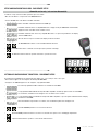
SETUP AND CONFIGURATION BY DRS - DMX REMOTE SETUP
The DRS it’s a new concept of professional LED Lighting fixtures suitable for outdoor permanent installations.
The LED Lighting fixtures can be driven via DMX through a specific electronic device, the DRS DMX Remote Setup, that grant the
possibility to set up the scenarios and the games remotely.
These LED Lighting fixtures have installed on board a series of programs including the stand alone function.
The DRS is a simple set up commander that linked with the DMX input of a LED Lighting fixture allow to program all the functions of the luminaire.
It’s than possible to assign the DMX channel or use the Master/Slave function.
The device is powered through battery.
DRS è il nuovo concetto dell’illuminazione LED per uso professionale nelle installazioni esterne permanenti.
Gli apparecchi LED possono essere controllati e configurati tramite uno specifico controller: il DRS, DMX Remote Setup, il quale consente di programmare e
configurare scene e giochi di luce in modalità remota.
Questi apparecchi LED hanno installati a bordo una serie di giochi che includono la funzione stand alone.
Il DRS, DMX Remote Setup, è un semplice set-up commander che collegato via DMX ad un’apparecchio consente la sua programmazione e configurazione.
E’ possibile assegnare agli apprecchi collegati i canali DMX o utilizzazre la funzione Master/Slave.
Il DRS è alimentato a batterie.
DMX line
XRL - LLT
connector
MAIN Power
Powered through
battery
RDM CONSOLE
.................................................................................................................. ITA
SETTAGGIO E CONFIGURAZIONE TRAMITE DRS - DMX REMOTE SETUP

rel.2_06/23 - Studio Due
15
.................................................................................................................. ITA
SETTAGGIO E CONFIGURAZIONE TRAMITE DRS - DMX REMOTE SETUP
Per effettuare la programmazione dei vari parametri di un apparecchio, è necessario procedere come segue:
• Disconnettere l’apparecchio da configurare da altri dispositivi DMX/RDM
• Collegare il cavo DMX dell’apparecchio da configurare, al programmatore DRS
• Accendere il programmatore DRS ed attendere che visualizzi la scritta 8888
• Se il programmatore DRS individua un dispositivo DRS compatibile, visualizza per qualche istante la scritta Conn e,
successivamente, visualizza il nome dell’apparecchio e la relativa versione software
• Se il programmatore DRS non individua alcun dispositivo DRS compatibile o è presente qualche malfunzionamento il display
visualizzerà la scritta SCAn
• Una volta terminata la sequenza di riconoscimento, viene visualizzato il primo menu dell’apparecchio
• I pulsanti UP/DOWN permettono di scorrere la lista dei menu
• Il pulsante ENTER permettere di entrare in un menu o di confermare una opzione in caso di lampeggio del parametro
• Il pulsante ESC annulla una operazione o torna al livello di menu inferiore.
.................................................................................................................. ENG
SETUP AND CONFIGURATION BY DRS - DMX REMOTE SETUP
To make the set-up of the various fixture parameter, proceed as follow:
•Disconnect the fixture to set-up from the other DMX/RDM devices
• Connect the DMX cable of the fixture to the DRS commander
• Switch on the DRS commander and wait for the 8888 sign
• If the DRS commander detects a compatible DRS device, displays shortly the Conn written and afterwards,
displays the name of the fixture and its software version.
• If the DRS commander dont’ detects any compatible DRS device or is present any malfunction, the display
shows the SCAn written
• When the detection sequence is finished, the display shows the first menu
• The UP/DOWN buttons allow to scroll forward/backward the menu list
• The ENTER button allow to confirm the selected option (if the parameter is flashing)
• The ESC button allow to delete the operation and return to a previus menu level
dimmable version only / solo versione dimmerabile

rel. 2_06/23 - Studio Due 16
Switching on the fixture you can see the model and the software version. For example:
All’accensione, viene visualizzato il modello di apparecchio e la versione software. Per esempio:
--> PL300 --> 1_00 - than it’s shown the fist menu / poi viene visualizzato il primo menu
Address (Addr) Set the DMX channel address / Imposta il canale DMX
> Select the channel number .. c001 .. c002 .. whit the UP/DOWN buttons. Press ENTER.
> Selezionate il canale desidarato .. c001 .. c002 .. con i tasti UP/DOWN. Premere ENTER.
Auto Mode (ModE) Set the DMX, SLAVE or MASTER mode / Imposta la modalità DMX, SLAVE o MASTER
> Select the value no .. sl .. pr01 .. pr02 .. with the UP/DOWN buttons. Press ENTER.
> Selezionate il valore desidarato no .. sl .. pr01 .. pr02 .. con i tasti UP/DOWN. Premere ENTER.
Auto Speed (PrSP) Set the preset execution speed / Imposta la velocità di esecuzione dei giochi interni
> Select the value +400% .. -400% with the UP/DOWN buttons. Press ENTER.
> Selezionate il valore desiderato +400% .. -400% con i tasti UP/DOWN. Premere ENTER.
Wireless enable (ULEn) Enable or disable the wireless reception / Consente o non consente la ricezione wireless. (ON, OFF)
The cable reception is disabled / La ricezione via cavo viene disabilita
> Select the value on .. off .. with the UP/DOWN buttons. The written is flashing, press ENTER.
> Selezionate il valore desidarato on .. off .. con i tasti UP/DOWN. La scritta lampeggia, premere ENTER.
Wireless unlink (ULPA) Remove the link from the fixture to the associated transmitter (PA?). Press ENTER.
Elimina il link tra l’apparecchio e il trasmettitore al quale è stato associato. Premere ENTER.
Wireless bridge (ULbr) If wireless is ON, enable the transmission of the received data by cable to the other fixtures
Se il wireless è attivo, consente la trasmissione dati agli altri apprecchi collegati via cavo. (ON, OFF)
> Select the value on .. off .. with the UP/DOWN buttons. Press ENTER.
> Selezionate il valore desidarato on .. off .. con i tasti UP/DOWN. Premere ENTER.
Scene (Scne)
N. Channels (nChn) Set the DMX channels of the fixture / Imposta il numero di canali DMX dell’apparecchio. (10, 7, 6, 5)
> Select the value, e.g. .. 7.. 5 etc. with the UP/DOWN buttons. Press ENTER.
> Selezionate il valore desidarato, per esempio .. 7 .. 5 etc. con i tasti UP/DOWN. Premere ENTER.
Flicker free function (FLcr) Flicker free function / Funzione flicker free. (F1, F2)
> Select the value f1 .. f2
> Selezionate il valore desidarato f1 .. f2
Smooth Dimming (SMth) Set the interpolation type for the smooth dimming function
Imposta il tipo di interpolazione per la funzione smooth dimming. (OFF, Sd1, Sd2, Sd3)
> Select the value oFF .. LoW .. MId .. hIGh with the UP/DOWN buttons. Press ENTER.
> Selezionate il valore desidarato oFF .. LoW .. MId .. hIGh con i tasti UP/DOWN. Premere ENTER.
.................................................................................................................. ENG / ITA
DRS MENU’ LIST / ELENCO MENU DRS
For each color or menu it is possible to varying and than set-up the value from 0 to
255 without having to confirm with the ENTER key.
These functions are auto-save.
Per ogni singolo colore o menu, è possibile variare e quindi impostare il valore da
0 a 255 senza dover confermare con il tasto ENTER.
Queste funzioni si salvano automaticamente.
red - ch1
green - ch2
blue - ch3
white - ch4

rel.2_06/23 - Studio Due
17
Halogen Simulation (HALS) Set the alogen simulation function mode
Imposta il funzionamento della modalità simulazione lampada alogena. (OFF, Mod1, Mod2)
> Select the value oFF .. MId1 .. MId2 with the UP/DOWN buttons. Press ENTER.
> Selezionate il valore desiderato oFF .. MId1 .. MId2 con i tasti UP/DOWN. Premere ENTER.
CYM Emulation (CYMS) Set the fixture to work in CYM or RGB emulation system
Imposta l’apparecchio per funzionare come emulatore di sistema CYM o RGB. (CYM, RGB)
> Select the value off >> RGB or on >> CYM with the UP/DOWN buttons. Press ENTER.
> Selezionate il valore desiderato off >> RGB oppure on >> CYM con i tasti UP/DOWN. Premere ENTER.
Test (tESt) Enables the test of the fixture and execute a factory program to check the right functioning/
Abilita il test dell’apparecchio ed esegue un programma di fabbrica per verificarne il funzionamento. (T-ON)
> Select the value t-on with the UP/DOWN buttons. T-on is flashing: test in progress. Press any key to exit.
> Selezionate il valore t-on con i tasti UP/DOWN. T-on lampeggia: test in corso. Premere qualsiasi tasto per uscire.
Reset (rSEt) Execute a reset of the electronic section / Esegue un reset della parte elettronica. (rS?)
Format (FrMt) Restore the factory setting (Require confirmation).
Ripristina le impostazioni di fabbrica (Viene chiesta conferma). (Fm?)

rel. 2_06/23 - Studio Due 18
DMX Channels list 9Ch / Lista dei canali DMX 9Ch
8 BIT FUNCTION 0 31 63 95 127 159 191 233 255
CH1 RED
CH2 GREEN
CH3 BLUE
CH4 WHITE
CH5 STROBE
FLASH 0,4Hz / 25Hz
2 -127
OPEN
0 - 1
RAINBOW - FLASH 0,4Hz / 25Hz
128 -255
CH6 DIMMER
CH7 LED FADE
TIME
FAST - 0,1 sec.
0 = CUT SLOW
25,5 sec.
LINEAR
CH8 RAINBOW
CH9 BALANCED
WHITE 0 - 15 NORMAL 16 - 255
WW CW
8 BIT FUNCTION 0 31 63 95 127 159 191 233 255
CH1 RED
CH2 GREEN
CH3 BLUE
CH4 WHITE
CH5 DIMMER
CH6 RAINBOW
DMX Channels list 6Ch / Lista dei canali DMX 6Ch

rel.2_06/23 - Studio Due
19
DMX Channels list 5Ch / Lista dei canali DMX 5Ch
DMX Channels list 4Ch / Lista dei canali DMX 4Ch
8 BIT FUNCTION 0 31 63 95 127 159 191 233 255
CH1 RED
CH2 GREEN
CH3 BLUE
CH4 WHITE
CH5 DIMMER
8 BIT FUNCTION 0 31 63 95 127 159 191 233 255
CH1 RED
CH2 GREEN
CH3 BLUE
CH4 WHITE

rel. 2_06/23 - Studio Due 20
DMX
512
DMX
512
8 BIT FUNCTION 0 31 63 95 127 159 191 233 255
CH1 DIMMER
CH2 STROBE
FLASH 0,4Hz / 25Hz
2 -127
OPEN
0 - 1
RAINBOW - FLASH 0,4Hz / 25Hz
128 -255
CH3 LED FADE
TIME
FAST - 0,1 sec.
0 = CUT SLOW
25,5 sec.
LINEAR
8 BIT FUNCTION 0 31 63 95 127 159 191 233 255
CH1 DIMMER
.................................................................................................................. ENG / ITA
DMX CHANNELS / CANALI DMX
- (*) DMX line for Dimmable version. (setting 3ch or 1ch)
--------------------------------------------------------------------------------------------------------------
- (*) linea DMX versione Dimmerabile. (settaggio 3ch o 1ch)
OPTIONAL CONNECTION TO DALI / CONNESSIONE OPZIONALE ALLA LINEA DALI
- (**) DALI line refer to next page to see the connection **.
- (**) linea DALI fare riferimento alla pagina seguente per i collegamenti **.
OPTIONAL CONNECTION TO DMX LINE / CONNESSIONE OPZIONALE ALLA LINEA DMX
- (*) DMX line for Dimmable version. (setting 3ch or 1ch)
- (*) linea DMX versione Dimmerabile. (settaggio 3ch o 1ch)
DMX
512
DMX
512
8 BIT FUNCTION 0 31 63 95 127 159 191 233 255
CH1 DIMMER
CH2 STROBE
FLASH 0,4Hz / 25Hz
2 -127
OPEN
0 - 1
RAINBOW - FLASH 0,4Hz / 25Hz
128 -255
CH3 LED FADE
TIME
FAST - 0,1 sec.
0 = CUT SLOW
25,5 sec.
LINEAR
8 BIT FUNCTION 0 31 63 95 127 159 191 233 255
CH1 DIMMER
La pagina si sta caricando...
La pagina si sta caricando...
La pagina si sta caricando...
La pagina si sta caricando...
-
 1
1
-
 2
2
-
 3
3
-
 4
4
-
 5
5
-
 6
6
-
 7
7
-
 8
8
-
 9
9
-
 10
10
-
 11
11
-
 12
12
-
 13
13
-
 14
14
-
 15
15
-
 16
16
-
 17
17
-
 18
18
-
 19
19
-
 20
20
-
 21
21
-
 22
22
-
 23
23
-
 24
24


STUDIO DUE PARLED 300 PRO RGBW IP20 Manuale utente
- Categoria
- Illuminazione di comodità
- Tipo
- Manuale utente
in altre lingue
Documenti correlati
-
 STUDIO DUE MEGAWHITE 66 M DALI Manuale utente
-
 STUDIO DUE T-COLOR 6C RGBWA+UV Manuale utente
-
 STUDIO DUE Easy Color 12.P Manuale utente
-
 STUDIO DUE SLIMBAR FLAT RGBW 50cm Manuale utente
-
 STUDIO DUE PL MAX Manuale utente
-
 STUDIO DUE COMPACTBAR RGBW 100cm Manuale utente
-
 STUDIO DUE ARCHILED 200 M DALI Manuale utente
-
 STUDIO DUE SLIMBAR PLUS POB W 100 cm Manuale utente
-
 STUDIO DUE CITYBEAM LED SL84 RGBW Manuale utente
-
 STUDIO DUE nanoLED User's And Operator's Manual


Altri documenti
-
CAME RIOCONN01 Guida d'installazione
-
 STUDIODUE 0303 Manuale del proprietario
-
Griven Parade L MC 2 Recessed RGBW Manuale del proprietario
-
-
-
-
Griven Moon wall Dynamic White Manuale del proprietario
-
-
-
ProLights PIXIEZOOM Manuale utente
