
3
4
5
1 6 FUNZIONAMENTO
Manuale d’Uso
CONTATORE DI ENERGIA BIDIREZIONALE
Leggere attentamente tutte le istruzioni
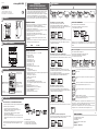
DIMENSIONI
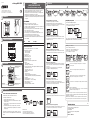
SCHEMI DI COLLEGAMENTO
DESCRIZIONE
INSTALLAZIONE
2
Mod. Energy-400 Bi PWR
Il contatore statico di energia Energy-400 Bi PWR è un dispositivo elettronico
per il conteggio dell’energia attiva sia prelevata che immessa in rete nei
sistemi trifase a 400Vac. E’ destinato ad operare in ambienti con categoria di
sovratensione III e grado di inquinamento 2, secondo la norma EN 61010-1.
Il contatore Energy-400 Bi PWR è conforme alla direttiva MID (2004/22/CE) ed è
previsto per l’uso in ambiente meccanico di tipo M1 ed elettromagnetico di tipo E2.
AVVERTENZE DI SICUREZZA
Per garantire una corretta installazione, occorre rispettare le seguenti indicazioni:
1) Il dispositivo deve essere installato da persona qualificata
2) Il dispositivo deve essere installato in un quadro tale da garantire, dopo
l’installazione, l’inaccessibilità ai morsetti
3) Nell’impianto elettrico a monte del contatore di energia deve essere installato
un dispositivo di protezione contro le sovracorrenti
4) Collegare il dispositivo seguendo gli schemi riportati a lato
5) Prima di accedere ai morsetti, assicurarsi che i conduttori da collegare allo
strumento non siano in tensione
6) Non alimentare e collegare il dispositivo se qualche parte di esso risulta
danneggiata
7) Il dispositivo deve essere installato e messo in funzione in conformità con la
normativa vigente in materia di impianti elettrici.
Codice Modello Descrizione
VE764600 Energy-400 Bi PWR Contatore di energia trifase bidirezionale
CARATTERISTICHE TECNICHE
• Alimentazione: 3x230 (400)V AC (-15% ÷ +10%), 50/60Hz
• Autoconsumo massimo:
– circuiti di tensione: 2,5 VA
– circuiti di corrente: 2,5 VA
• Corrente di ingresso In: 5A
• Corrente di avviamento Ist: 0,01A
• Corrente di transizione Itr: 0,25A
• Corrente minima Imin: 0,05A
• Corrente massima Imax: 6A
• Inserzione amperometrica tramite TA esterni x/5A
• Risoluzione:
– energia totale: 1kWh
– energia parziale: 0,01kW (autoscala)
•
Uscita impulsi: optoisolata per la lettura remota del conteggio dell’energia prelevata
– durata impulso: 100ms ± 15%
– tensione impulso: 9÷24V DC ±10%
– massima corrente di uscita: 20 mA
• Led di segnalazione:
– verde: presenza alimentazione
– giallo: indica energia immessa (produzione da fotovoltaico)
– rosso: lampeggiante con frequenza 1/5 kWh (sia immessa che prelevata)
• Indice di classe: B
• Temperatura di funzionamento: -10 ÷ +45°C
• Umidità di funzionamento: 10%÷90% non condensante
• Temperatura di immagazzinamento -25 ÷ +70°C
• Contenitore: 3 moduli DIN
• Grado di protezione: IP20/IP51 sul frontale
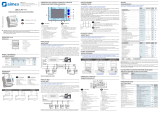
123456 7
Sel Sel Sel Sel Sel Sel
Sel
Energia prelevata totale
Energia prelevata parziale
Energia immessa totale
Energia immessa parziale
Energia immessa
totale
Energia immessa
parziale
Energia prelevata
totale
Energia prelevata
parziale
Potenza
prelevata/immessa
2 Visualizzazione energia prelevata (consumata) totale
Energia prelevata totale (7 digits), risoluzione 1kWh. Contatore non azzerabile.
Da questa schermata, premere a lungo il tasto “Sel”, per accedere alla
visualizzazione del TA impostato.
Sel 3"
1 Visualizzazione energia prelevata (consumata)
Energia prelevata totale (7 digits), risoluzione 1kWh
Energia prelevata parziale (5 digits), risoluzione 0,01kWh (autoscala)
Da questa schermata, premere a lungo il tasto “Sel”, per attivare la verifica
dei collegamenti (vedere “Verifica dei collegamenti”)
Sel 3"
3 Visualizzazione energia prelevata (consumata) parziale
Energia prelevata parziale (5 digits), risoluzione 0,01kWh. Contatore azzerabile.
Da questa schermata, premere a lungo il tasto “Sel”, per azzerare il contatore.
Sel 3"
4 Visualizzazione potenza e power factor
Power factor (PF) e potenza istantanea prelevata (
►
) o immessa (
◄
).
Visualizzazione delle grandezze di Sistema (L per power factor di tipo indut-
tivo, [ per power factor di tipo capacitivo).
Da questa schermata, premere il tasto “Sel”, per accedere all’impostazione
della retroilluminazione (vedere “Gestione della retroilluminazione”)
Sel 3"
54
87
37
48
64
1 2 9875 64
141311 2110
3
18
17
51 61
9 ÷ 24 V
I = 20mA
max
1 kWh/imp
+
+ -
L1
N
L3
L2
L1
L3
L2
+ -+ -
Energia immessa Energia prelevata
Morsetti per l’inserzione
dei conduttori di tensione
Morsetti per l’inserzione
dei conduttori di corrente
Morsetti per
l’uscita impulsi
Tasto SEL:
- pressione (corta): <3 secondi
- pressione lunga: >3 secondi
Energy-400 Bi PWR
ON
Sel
imp
kWh
VE764600
3x230(400)V~ 50Hz
0,05-5(6)A cl. B
5
V3IS00868-010
Vemer S.p.A.
I - 32032 Feltre (BL) • Via Camp Lonc, 16
Tel +39 0439 80638 • Fax +39 0439 80619
e-mail: info@vemer.it - web site: www.vemer.it
In caso di segnalazione di errore, per ripristinare il corretto funzionamento, occorre spe-
gnere il contatore, controllare che il collegamento delle tensioni e delle correnti rispecchi
lo schema riportato in questo manuale e quindi riaccendere il contatore.
Importante: esistono combinazioni di errori che si compensano. In questi casi non è possi-
bile segnalare l’errore e il contatore misura un valore dell’energia non corretto.
IMPOSTAZIONE RAPPORTO DI TRASFORMAZIONE AMPEROMETRICO
Le impostazioni predefinite prevedono un rapporto di trasformazione TA 5/5A.
Per modificare il rapporto di trasformazione:
1 tenere premuto il tasto “Sel” e alimentare il contatore
2 attendere che il display visualizzi la schermata del rapporto di
trasformazione PRitA e rilasciare il tasto
3 premere a lungo il tasto “Sel” finchè il valore del rapporto di
trasformazione inizia a lampeggiare
4 impostare il rapporto di trasformazione premendo il tasto “Sel”. L’uscita
dal menù avviene in automatico dopo circa 4 secondi senza la pressione
del tasto.
La variazione del rapporto di trasformazione provoca un riavvio del contatore.
Il valore dei contatori rimangono invariati al valore raggiunto fino a quel
momento.
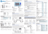
Il contatore segnala la presenza dei seguenti errori nei collegamenti:
Errore di inserzione ingressi di tensione: non è rispettata la sequenza delle
fasi L1-L2-L3
Errore di inserzione ingressi di tensione su due fasi (in questo caso L1
e L2)
Errore no Power detection: viene misurata una potenza nulla (tensione o
corrente nulla) in una delle fasi (in questo caso L1 e L3)
Errore di inserzione ingressi di corrente su due fasi (in questo caso L2 e
L3)
Nessuna condizione di errore rilevata.
In questo caso il contatore visualizza no Error per due secondi per poi
tornare alla Visualizzazione dell’energia 1 o 5 .
Valori dei TA impostabili:
- da 5/5 A a 200/5 A, con incrementi di 5
- da 200/5 A a 1000/5 A, con incrementi di 50
- da 1000/5 A a 2500/5 A, con incrementi di 100
5 Visualizzazione energia immessa (prodotta)
Energia immessa totale (7 digits), risoluzione 1kWh.
Energia immessa parziale (5 digits), risoluzione 0,01kWh (autoscala).
Da questa schermata, premere a lungo il tasto “Sel”, per attivare la verifica dei
collegamenti (vedere “Verifica dei collegamenti”)
Sel 3"
7 Visualizzazione energia immessa (prodotta) parziale
Energia immessa parziale (5 digits), risoluzione 0,01kWh. Contatore azzerabile.
Da questa schermata, premere “Sel”, per azzerrare il contatore.
Sel 3"
Sel 3"
Sel
Sel
4
6 Visualizzazione energia immessa (prodotta) totale
Energia immessa totale (7 digits), risoluzione 1kWh. Contatore non azzerabile.
Sel 3"
4"
NORME DI RIFERIMENTO
La conformità alle direttive comunitarie:
2014/35/UE (Bassa Tensione)
2004/22/CE (MID)
è dichiarata in riferimento alle Norme seguenti:
CEI EN 61010-1,
CEI EN 50470-1, CEI EN 50470-3
4-2017
Gestione della retroilluminazione
Per accedere alla “Gestione della retroilluminazione”:
• dalla schermata “4. Visualizzazione potenza e power factor”,
tenere premuto a lungo il tasto “Sel”.
Sel 3"
5
1
Sel 3"
Verifica dei collegamenti
Per accedere alla “Verifica dei collegamenti”:
• dalla schermata “1. Visualizzazione energia prelevata” oppure
• dalla schermata “5. Visualizzazione energia immessa”,
tenere premuto a lungo il tasto “Sel”.
Scegliere 0N per avere la retroilluminazione sempre attiva oppure TI E (impostazione
predefinita) per avere la retroilluminazione attivi nei 30 secondi successivi alla pressione
del tasto.

3
4
5
1 6 OPERATION
User manual
BIDIRECTIONAL ENERGY METER
Read all the instructions carefully
DIMENSIONS
CONNECTION DIAGRAMS
DESCRIPTION
INSTALLATION
2
Mod. Energy-400 Bi PWR
The Energy-400 Bi PWR static energy meter is an appliance to read active
energy both withdrawn and injected in three-phase 400Vac systems.
It is designed to operate in environments with category of overvoltage III and
pollution degree 2 according to EN 61010-1 standard.
The energy meter Energy-400 Bi PWR is in compliance with MID (2004/22/CE) and
it’s suitable for use in mechanical environment of type M1 and in electromagnetic
one of type E2.
SAFETY WARNINGS
To guarantee correct installation, proceed as follows:
1) The appliance should be installed by a qualified operator
2) The appliance should be installed in a panel in such a way as to guarantee that
the terminals are inaccessible after fitting
3) A protection device against over-currents should be installed in the electrical
system, upstream of the energy meter
4) Connect the instrument as shown in the alongside diagrams
5) Before touching the connector terminals make sure that the wires to be con-
nected or already connected to the instrument are not live
6) Do not power or connect the device if any part of it is damaged
7) The device must be installed and activated in compliance with current electric
systems standards.
Codice Model Description
VE764600 Energy-400 Bi PWR
Three-phase bidirectional energy meter
TECHNICAL SPECIFICATIONS
• Power supply: 3x230 (400)V AC (-15% ÷ +10%), 50/60Hz
• Maximum power consumption:
- voltage circuits: 2.5 VA
- current circuits: 2.5 VA
• Input current In: 5A
• Starting current Ist: 0.01A
• Transition current Itr: 0.25A
• Minimum current Imin: 0.05 A
• Maximum current Imax: 6A
• Amperometric connection through external CT x/5A
• Resolution:
- total energy: 1kWh
- partial energy: 0.01kW (autoscale)
• Pulse output: optoisolated for remote reading of the withdrawn energy counting
- pulse duration: 100ms ± 15%
- pulse voltage: 9 ÷ 24V DC ± 10%
- maximum output current: 20 mA
• Signaling led:
- green: power supply
- yellow: injected energy (photovoltaic production)
- red: flashing with frequency 1/5 kWh (both injected and withdrawn)
• Class index: B
• Operating temperature: -10 ÷ +45 °C
• Operating humidity: 10% ÷ 90% noncondensing
• Storage temperature -25 ÷ + 70 ° C
• Container: 3 DIN modules
• Protection degree: IP20/IP51on the frontal
123456 7
Sel Sel Sel Sel Sel Sel
Sel
Total withdrawn energy
Partial withdrawn energy
Total injected energy
Partial injected energy
Total injected
energy
Partial injected
energy
Total withdrawn
energy
Partial withdrawn
energy
Withdrawn/injected
power
2 Display of total withdrawn energy (consumed)
Total withdrawn energy (7 digits), resolution 1kWh. The counter can not be
reset. From this screen, press the “Sel” key for a long time to access the
visualization of the set CT.
Sel 3"
1 Display of withdrawn energy (consumed)
Total withdrawn energy (7 digits), resolution 1kWh
Partial withdrawn energy (5 digits), resolution 0.01kWh (autoscale)
From this screen, press the “Sel” key for a long time to activate the check of
the connections (see “Checking the connections”)
Sel 3"
3 Display of partial withdrawn energy (consumed)
Partial withdrawn energy (5 digits), resolution 0.01kWh. The counter can not be
reset. From this screen, press the “Sel” key for a long time to reset the counter.
Sel 3"
4 Display of power and power factor
Power factor (PF) and withdrawn instantaneous power (
►
) or injected (
◄
).
Display of System sizes (L for inductive power factor, [ for capacitive type
power factor).
From this screen, press the “Sel” key to access the setting of the
backlighting (see “Backlighting management”)
Sel 3"
54
87
37
48
64
1 2 9875 64
141311 2110
3
18
17
51 61
9 ÷ 24 V
I = 20mA
max
1 kWh/imp
+
+ -
L1
N
L3
L2
L1
L3
L2
+ -+ -
Energia immessa Energia prelevata
Morsetti per l’inserzione
dei conduttori di tensione
Morsetti per l’inserzione
dei conduttori di corrente
Morsetti per
l’uscita impulsi
Tasto SEL:
- pressione (corta): <3 secondi
- pressione lunga: >3 secondi
Energy-400 Bi PWR
ON
Sel
imp
kWh
VE764600
3x230(400)V~ 50Hz
0,05-5(6)A cl. B
5
V3IS00868-010
Vemer S.p.A.
I - 32032 Feltre (BL) • Via Camp Lonc, 16
Tel +39 0439 80638 • Fax +39 0439 80619
e-mail: info@vemer.it - web site: www.vemer.it
In case of error message, to restore the correct operation, you must turn off the counter,
check that the connections of the voltage and currents mirror the diagram of this manual,
and then turn on the meter again.
Important: there are combinations of errors that compensate each other. In such cases it
is not possible to report the error and the counter measures an incorrect energy value.
SETTING THE AMPEROMETRIC TRANSFORMATION RATIO
The default settings have a transformation ratio CT 5/5A.
To change the transformation ratio:
1 press the “Sel” key and power the counter
2 when the display shows the screen of transformation ratio PRitA you
can release the key
3 press the “Sel” key for a long time until the value of the transformation
ratio begins to flash
4 set the transformation ratio by pressing the “Sel” key. The exit from
the menu occurs automatically after approximately 4 seconds without
pressing any key.
The variation of the transformation ratio causes a restarting of the counter.
The value of the counters remain unchanged at the value reached until that
moment.
The counter indicates the following errors during the connections:
Connection error of voltage input: the sequence of L1-L2-L3 phases
is not respected
Connection error of voltage input on two phases (in this case L1
and L2)
No Power detection error: zero power is measured (zero voltage or
current) in one of the phases (in this case L1 and L3)
Connection error of current inputs on two phases (in this case L2 and L3)
No error condition detected.
In this case the counter will display no Error for two seconds then it
will return to the Display of energy 1 or 5.
Settable CT values:
- from 5/5 A to 200/5 A, by increments of 5
- from 200/5 A to 1000/5 A, by increments of 50
- from 1000/5 A to 2500/5 A, by increments of 100
5 Display of injected energy (produced)
Total injected energy (7 digits), resolution 1kWh.
Partial injected energy (5 digits), resolution 0.01kWh (autoscale).
From this screen, press the “Sel” key for a long time, to activate the check
of the connections (see “Checking the connections”)
Sel 3"
7 Display of partial injected energy (produced)
Partial injected energy (5 digits), resolution 0.01kWh. The counter can not be
reset. From this screen, press the “Sel” key to reset the counter.
Sel 3"
Sel 3"
Sel
Sel
4
6 Display of total injected energy (produced)
Total injected energy (7 digits), resolution 1kWh. The counter can not be reset.
Sel 3"
4"
REFERENCE STANDARS
Conformity to European Community directives:
2014/35/EU (Low Voltage)
2004/22/EC (MID)
is declared according to the following standards:
EN 61010-1,
EN 50470-0, EN 50470-3
4-2017
Backlighting management
To access the “Backlighting management”:
• from the screen “4. Display of power and power factor”,
press the “Sel” key for a long time.
Sel 3"
5
1
Sel 3"
Checking the connections
To access “Checking the connections”:
• from the screen “1. Display of withdrawn energy “or
• from the screen “5. Display of injected energy “,
press the “Sel” key for a long time.
Choose 0N to have the backlighting always active or TI E (default setting) to have the
backlighting active within 30 seconds after the pressure of the key.
Terminal blocks for connection
of the voltage wires
Withdrawn energyInjected energy
SEL key:
- short pressure: <3 seconds
- long pressure: >3 seconds
Terminal blocks
for pulse output
Terminal blocks for connection
of the current wires
-
 1
1
-
 2
2


in altre lingue
- English: Vemer Energy-400 Bi PWR User manual
Documenti correlati
Altri documenti
-
Socomec COUNTIS E4x Istruzioni per l'uso
-
Carel MT100D2100 Manuale utente
-
-
-
 Simex SEC-L70 Manuale del proprietario
-
-
-
 Simex SEC-L70 Manuale del proprietario

