
Bedienungsanleitung
Operation Manual
Innovation,
die bewegt!
ENDE
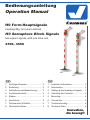
H0 Form-Hauptsignale
zweibegriffig, mit einem Antrieb
H0 Semaphore Block Signals
two-aspect signals, with one drive unit
4506, 4508
1. Wichtige Hinweise ......................... 2
2. Einleitung ....................................... 2
3. Aufstellung und Bezeichnung ........ 2
4. Funktionskontrolle ......................... 2
5. Einbau ........................................... 3
6. Anschluss ...................................... 3
7. Fehlersuche & Abhilfe ................... 3
8. Technische Daten .......................... 3
1. Important Information .................... 2
2. Introduction .................................... 2
3. Setting up and marking of signals .... 3
4. Checking the Function ................... 4
5. Mounting ........................................ 4
6. Connection .................................... 5
7. Trouble-shooting ............................ 8
8. Technical Data ............................... 8
4506
4508

2
DE
1. Wichtige Hinweise
Bitte lesen Sie vor der ersten Anwendung des Produktes bzw. dessen Einbau diese Bedienungsanleitung aufmerksam durch.
Bewahren Sie diese auf, sie ist Teil des Produktes.
1.1 Sicherheitshinweise
Vorsicht:
Verletzungsgefahr!
Aufgrund der detaillierten Abbildung des Originals bzw. der vorgesehenen Verwendung kann das Produkt Spitzen, Kanten und
abbruchgefährdete Teile aufweisen. Für die Montage sind Werkzeuge nötig.
Stromschlaggefahr!
Die Anschlussdrähte niemals in eine Steckdose einführen! Verwendetes Versorgungsgerät (Transformator, Netzteil) regelmäßig
auf Schäden überprüfen. Bei Schäden am Versorgungsgerät dieses keinesfalls benutzen!
Alle Anschluss- und Montagearbeiten nur bei abgeschalteter Betriebsspannung durchführen! Ausschließlich nach VDE/EN
gefertigte Modellbahntransformatoren verwenden! Stromquellen unbedingt so absichern, dass es bei einem Kurzschluss nicht
zum Kabelbrand kommen kann.
1.2 Das Produkt richtig verwenden
Dieses Produkt ist bestimmt:
- Zum Einbau in Modelleisenbahnanlagen und Dioramen.
- Zum Anschluss an einen Modellbahntransformator (z. B. Art. 5200/5201) bzw. an eine Modellbahnsteuerung mit zugelassener
Betriebsspannung.
- Zum Betrieb in trockenen Räumen.
Jeder darüber hinausgehende Gebrauch gilt als nicht bestimmungsgemäß. Für daraus resultierende Schäden haftet der Hersteller
nicht.
1.3 Packungsinhalt überprüfen
Kontrollieren Sie den Lieferumfang auf Vollständigkeit:
- Signalmodell mit Antriebseinheit
- Anleitung
2. Einleitung
Viessmann-Formsignale zeichnen sich durch vorbildgetreu langsame Flügelbewegung, ihr hervorragendes Preis-Leistungs-Ver-
hältnis sowie durch einfache Montage und Anschlussmöglichkeit aus. Das vorliegende Formsignal verfügt über einen elektro-
magnetischen Antrieb, eine Endlagenabschaltung und über einen Kontakt zur Zugbeeinflussung.
Viessmann-Formsignale haben sehr filigrane Masten, die sich durch eine perfekte Vorbildtreue auszeichnen. Daher sollten Sie das
Signal nie am Mast anfassen, sondern immer nur an der Bodenplatte bzw. am Antriebszylinder (Abb. 1). Bei einem Ausbau aus der
Modellbahnplatte nicht oben ziehen, sondern das Signal unter der Platte am Antriebszylinder greifen und nach oben hinausschieben!
3. Aufstellung und Bezeichnung
Hauptsignale stehen in Deutschland in der Regel in Fahrtrichtung gesehen rechts vom Gleis. Zweiflügelige Form-Hauptsignale
können als Ein- oder Ausfahrsignale im Bahnhofsbereich oder als Blocksignale auf der Strecke eingesetzt werden.
Damit ein Lokführer Signale richtig zuordnen oder im Störungsfall die richtige Meldung machen kann, werden die Signale mit einer
Buchstaben- / Zahlenkombination gekennzeichnet. Die Bezeichnung des Signals gibt zusätzlich Auskunft über seinen Standort.
Hier einige Richtlinien zur korrekten Beschriftung:
Blocksignale: Selbstblocksignale werden mit arabischen Zahlen (1, 2, 3, …) bezeichnet. In Richtung der Kilometrierung der Strecke
wird mit ungeraden Zahlen vorwärts gezählt (1, 3, 5, …), in der anderen Richtung mit geraden Zahlen rückwärts (z. B. 6, 4, 2, …).
Einfahrsignale: In Zählrichtung der Kilometrierung der Strecke werden für Einfahrsignale die Buchstaben „A“ bis „E“, in Gegen-
richtung „F“ bis „K“ verwendet.
Ausfahrsignale: Ausfahrsignale, die in Zählrichtung stehen, werden mit „N“ bezeichnet. Ausfahrsignale, die entgegen der Zähl-
richtung stehen, werden mit „P“ bezeichnet.
Hinter dem Buchstaben eines Ein- oder Ausfahrsignales steht die Ziffer des Gleises, für welches das Signal gilt.
Damit Sie Ihre Signale korrekt beschriften können, liegt dem Signal eine Tafel mit selbstklebenden Bezeichnungsschildern bei.
Schneiden Sie das gewünschte Schild aus, ziehen Sie die Schutzfolie ab und kleben Sie es auf die Nummerntafel am Mast des
Signals (Abb. 2).
Viele weitere Informationen über Signale finden Sie im Viessmann-Signalbuch, Art. 5299.
4. Funktionskontrolle
Nehmen Sie das Signal vorsichtig aus der Verpackung. Führen Sie vor der Montage eine Funktionskontrolle durch.
Schließen Sie dazu das gelbe Kabel (ohne Markierung) an einem Pol eines 16 V-Modellbahntransformators (z. B. Viessmann
Art. 5200/5201) an.

3
Verbinden Sie abwechselnd jeweils ein blaues Kabel mit dem anderen Pol des Trafos. Niemals die blauen Kabel gleichzeitig
anschließen. Das kann zur Zerstörung des Signals führen.
Blau mit roter Markierung: Signal auf „Halt“ (Hp0), oberer Flügel waagerecht (wenn vorhanden: unterer Flügel senkrecht)
Blau mit grüner Markierung: Signal auf „Fahrt“ (Hp1) bzw. Langsamfahrt (Hp2), oberer Flügel schräg nach oben (wenn vorhanden:
unterer Flügel ebenfalls schräg nach oben).
5. Einbau
1. Beschriften Sie das Signal (siehe Kapitel 3).
2. Sägen Sie an der Montagestelle ein Loch mit den Maßen 15 x 15 mm. Bohren Sie dazu zuerst 4 Löcher mit 6 mm Durchmesser.
Verwenden Sie die in der Abb. 3 abgedruckte Schablone.
3. Führen Sie die Anschlusskabel von oben durch das Montageloch und stecken Sie dann das Signal mit dem Antrieb voran hinein
4. Halten Sie die Bodenplatte des Signals jetzt von oben fest. Schieben Sie den Befestigungsring von unten so auf den Antrieb,
dass die Rastnasen um 90° zu der Riffelung am Gehäuse des Antriebes verdreht sind. Wenn nun die 4 Kunststofflaschen des
Befestigungsringes mit der Anlagenplatte unter mechanischer Spannung stehen, drehen Sie den Ring so, dass die Nasen in
der Riffelung des Antriebsgehäuses für einen festen Halt sorgen.
6. Anschluss
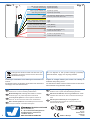
Schließen Sie das Signal gemäß den Abb. 5 oder 6 an. Zur Bedeutung der Kabelfarben siehe Abb. 7.
Für die Versorgung der Signalbeleuchtung empfehlen wir einen separaten Transformator. Das verhindert ein eventuelles Flackern
der Beleuchtung beim Umschalten des Signales durch den erhöhten Strombedarf des Antriebes.
Gleichstrombetrieb: Schließen Sie die beiden gelben Kabel an den Minuspol des Trafos an.
Achtung: Bei Betrieb mit Dauerstrom kann die Antriebsspule beschädigt werden, wenn die Schaltspannung zu niedrig ist und
deshalb die Endabschaltung nicht erreicht wird. Empfehlung: Schalten per Impuls (z. B. Taster statt Schalter) mit Wechselspannung.
6.1 Analoge Ansteuerung
Abb. 6 zeigt, wie einfach Sie die zweibegriffigen Formsignale mit Hilfe der Viessmann Tastenstellpulte Art. 5547 (ohne Rückmeldung)
oder Art. 5549 (mit Rückmeldung durch LEDs) anschließen können. Schalter, Taster und Relais anderer Hersteller können Sie
natürlich auch verwenden.
6.2 Digitale Ansteuerung
Viessmann-Formsignale können auch von einem Digitalsystem angesteuert werden (Abb. 5). Beim Anschluss z. B. an den
Viessmann-Magnetartikel-Decoder Art. 5211 (Märklin / Motorola) müssen Sie darauf achten, dass neben den blauen Kabeln zur
Signalsteuerung auch das gelbe Kabel (ohne Markierung) für die Stromversorgung angeschlossen ist. Zum digitalen Schalten
eines zweibegriffigen Signals wird eine Ausgangsgruppe eines Magnetartikeldecoders benötigt (s. Abb. 7).
Der 5211 (4-fach) ist kompatibel mit dem Märklin / Motorola und dem Märklin-Systems-Format. Der 5212 (4-fach) ist kompatibel mit
allen DCC-Digitalsystemen wie z. B. Digital plus (Lenz), Arnold Digital, Roco Digital, Fleischmann Twin Center, Digitrax, Uhlenbrock
Intellibox, Tillig Digital usw.
7. Fehlersuche & Abhilfe
Jedes Viessmann-Produkt wird unter hohen Qualitätsstandards gefertigt und vor seiner Auslieferung geprüft. Sollte es dennoch
zu einer Störung kommen, können Sie anhand der folgenden Punkte eine erste Überprüfung vornehmen. Testen Sie jedoch zuvor
die Stromzuführungen.
1. Die Flügel stehen nicht gerade:
Signal auf Stellung „Halt“ (Hp0) stellen und Flügel vorsichtig gerade stellen. Jeder Flügel lässt sich auf seiner Drehachse
verstellen. Unter Umständen müssen Sie die auf der Rückseite befindlichen Anschläge etwas nachrichten.
2. Das Signal schaltet hörbar, die Flügel bewegen sich jedoch nicht oder nur teilweise:
Hubstangen vorsichtig etwas nach oben oder unten bewegen. Eventuell die Hubstangen oben lösen und prüfen, ob die Flügel-
mechaniken sich widerstandslos bewegen lassen.
Sollte das Produkt beschädigt sein und Sie finden die Fehlerursache nicht, nehmen Sie bitte Kontakt mit uns auf (service@
viessmann-modell.com). Senden Sie uns den Artikel zur Kontrolle bzw. Reparatur bitte erst nach Rücksprache zu.
8. Technische Daten
Betriebsspannung: 16 V AC~ / DC=
Stromaufnahme (im Schaltmoment, ca. 0,1 s): 0,7 A
Maximale Belastbarkeit des Fahrstromkontaktes: 2 A

4
EN
1. Important information
Please read this manual completely and attentively before using the product for the first time. Keep this manual. It is part of the
product.
1.1 Safety instructions
Caution:
Risk of injury!
Due to the detailed reproduction of the original and the intended use, this product can have peaks, edges and breakable parts.
Tools are required for installation.
Electrical hazard!
Never put the connecting wires into a power socket! Regularly examine the transformer for damage. In case of any damage,
do not use the transformer.
Make sure that the power supply is switched off when you mount the device and connect the cables! Only use VDE/EN tested
special model train transformers for the power supply! The power sources must be protected to avoid the risk of burning cables.
1.2 Using the product for its correct purpose
This product is intended:
- For installation in model train layouts and dioramas.
- For connection to an authorized model train transformer (e. g. item 5200/5201) or a digital command station.
- For operation in dry rooms only.
Using the product for any other purpose is not approved and is considered inappropriate. The manufacturer is not responsible for
any damage resulting from the improper use of this product.
1.3 Checking the package contents
Check the contents of the package for completeness:
- Signal model with drive unit
- Manual
2. Introduction
Viessmann semaphores have some outstanding benefits: Prototypically slow arm movement, very good cost/performance ratio
and they are simple to mount and connect.
This signal has an electromagnetic drive unit, end position stop and an integrated contact for train control.
Viessmann semaphores have finely detailed metal masts, which are very sensitive. Therefore, you should never touch the masts
but only the drive unit for installation and deinstallation (fig. 1).
If you have to unmount the signal, do not pull the signal mast. Carefully take the drive unit instead and push it up.
3. Setting up and marking of signals
Adhesive signs are supplied with the signal. Simply cut out the desired sign and attach it to the signal box after removing the
protecting foil. Here are some rules for the correct marking of the semaphore signals:
Signals are set on the right side of the track in Germany. Two-aspect signals can be used in stations and on the route.
Signals are marked with an alphanumeric combination The name of the signal gives information about its position and direction
of the route.
Block Signals: These signals are labelled with arabic numbers (1, 2, 3, ...). In direction of the kilometre count, the signals are counted
with odd numbers (e. g. 1, 3, 5, ...). In the opposite direction the signals are counted with even numbers backwards (e. g. 6, 4, 2, ...).
Entry Signals: In direction of the kilometre count of the route, the signals are labelled with the letters “A” to “E”, in the opposite
direction “F” to “K”.
Exit Signals: In direction of the kilometre count of the route, the signals are labelled with the letter “N”, in the opposite direction
with “P”.
The letter for an entry or exit signal is followed by the number of the track for which the signal is effective.
4. Checking the function
Remove the signal from the box carefully. Check all functions prior to installation.
Connect the yellow wire (the one without the resistor) to one of the terminals of a 16 V transformer (AC/DC) e. g. Viessmann item
5200/5201.
Then alternately connect each variety of the blue wires to the other terminal, but only briefly. Never connect the blue cables at
the same time to the transformer. This may destroy the signal.
Blue with red marking: Signal on “Stop” (Hp0), upper arm horizontal, (if existing: lower arm vertical).
Blue with green marking: Signal on “Proceed” (Hp1) or on Proceed slowly (Hp2), upper arm diagonal upwards, (if existing:
lower arm diagonal upwards).

5
5. Mounting
1) Label the signal in accordance with the instructions on page 3.
2) Saw a square hole of 15 x 15 mm at the mounting place. Start with drilling 4 holes of 6 mm diameter each in the corners. Please
use the pattern which is shown in fig. 3.
3) The signal‘s connection wires have to be inserted into the hole first. After that put the signal with the drive first into that hole.
4) Now the base plate of the signal has to be held in place (perhaps by a second person). Then push the mounting ring from below
onto the drive in such a manner that the tabs are at a right angle to the groves on the housing of the drive. Once the 4 plastic
tabs of the mounting ring are under tension, you turn the ring until the tabs lock against the groves on the housing.
6. Connection
Now make the electrical connection as per fig. 5 or 6. For the meaning of the cable colours refer to fig. 7.
As a supply for the signal light, we recommend a separate transformer. This will prevent flickering of the lights due to high
consumption of the drive.
Connect the signal light to the transformer via the yellow cable with black marking and the brown cable with the diode.
Direct current: Connect both yellow cables to the negative pole of the transformer.
Notice: When using constant current to operate the signal, the drive unit may be damaged due to a low switching voltage.
Recommendation: Operate the signal via pulses (e. g. push-button instead of switch) and with AC.
6.1 Analogue control
The analogue connection is shown in fig. 6. It shows how you can connect the two-aspect form signals to a push-button panel
(e. g. Viessmann items 5547 or 5549).
6.2 Digital control
The semaphore signals can also be operated with a digital system. Refer to fig. 5 on the following page for the correct connection.
Simply connect the cables to a digital decoder (e. g. Viessmann item 5211 for Märklin / Motorola format. Item 5212 is suitable for
the NMRA DCC format. Viessmann delivers decoders for all digital systems and standards:
Item 5211: Compatible with the Märklin / Motorola and Märklin-Systems format.
Item 5212: Compatible with all DCC-systems e. g. Digital plus (Lenz), Arnold Digital, Roco Digital, Fleischmann Twin Center,
Digitrax, Uhlenbrock Intellibox, Tillig Digital etc.
7. Trouble-shooting
Every Viessmann product is manufactured under high quality standards and is tested before delivery. Should a fault occur non-
withstanding, please undertake an initial check as per the following steps. At first check the power supply.
1. The arms are not straight:
Set the signal to the Hp0 aspect (Stop) and adjust the arm back to the straight position very carefully! The arm can be shifted
on its axle.
2. The switching sound of the signal drive can be heard, but the arm doesn‘t move or moves only a little bit.
Slightly move the lifting rod very carefully up and down (if necessary detach the lifting rod from the arm lever and check if
arm mechanics can be moved without resistance).
If the product is damaged and you cannot find the reason please contact our service department (service@viessmann-modell.
com). Please send the item to the Viessmann service department for checking and repair only after consultation.
8. Technical data
Operating voltage: 16 V AC~ / DC=
Peak inrush current (for ca. 0.1 s): 0.7 A
Max. contact load of the track control contact: 2 A

6
rt bn rt 1 gn rt 2 gn
ON
1 2 3 4 5 6 7 8
WP
Viessmann
5211
Magnetartikeldecoder
rt bn E gn 4 rt gn 3 rt
Diode
16 V ~ / =
16 V ~ / =
braun
grün
rot
blau
gelb
z. B. 5211
gelb
Digitalzentrale
Optional:
separater Anschluss des
Lichtstroms.
Widerstand
brown
green
red
blue
yellow
e. g. 5211
diode
resistor
Digital Command Station
Option:
separate power
supply for lights
yellow
Abb. 5 Fig. 5
90°
Abb. 4 Fig. 4
Fig. 1
Abb. 1 Fig. 2
Abb. 2
15 mm
15 mm
Ø 6 mm
Fig. 3Abb. 3

7
Universal Tasten - Stellpult
5549
Viessmann
braun
brown
grünrot
braun
brown
blau
rot
red
rot
red
braun
brown
gelb
yellow
z. B. 5549
e. g. 5549
Diode
Widerstand
braun
brown
grün
green
rot
red
braun
brown
blau
blue
rot
red
rot
red
braun
brown
gelb
yellow
z. B. 5549
e. g. 5549
Diode
Widerstand
Fig. 6
Abb. 6
System
Märklin H0
Beachten Sie die
Anschlusshinweise in
Kap. 6, S. 5
Note the connecting
instructions in chap. 6
on p. 5
Dieses Symbol neben dem Gleis
kennzeichnet eine Trennstelle
(Gleichstrom = rechte Schiene in
Fahrtrichtung, Wechselstrom = Mit-
telleiter).
This sign beside the track indicates
a track insulation (DC = right rail in
driving direction, AC = third rail).
Formsignal
mit einem Antrieb.
Semaphore Signal
with one drive unit.
16 V
Universal Tasten - Stellpult
5549
Viessmann
16 V

Modellbauartikel, kein Spielzeug! Nicht geeignet für
Kinder unter 14 Jahren! Anleitung aufbewahren!
Model building item, not a toy! Not suitable for children
under the age of 14 years! Keep these instructions!
Ce n’est pas un jouet! Ne convient pas aux enfants de
moins de 14 ans! Conservez cette notice d’instructions!
Não é um brinquedo! Não aconselhável para menores de
14 anos! Conservar o manual de instruções!
Modelbouwartikel, geen speelgoed! Niet geschikt voor
kinderen onder 14 jaar! Gebruiksaanwijzing bewaren!
Articolo di modellismo, non è un giocattolo! Non adatto
a bambini al di sotto dei 14 anni! Conservare istruzioni per
l’uso!
Artículo para modelismo ¡No es un juguete! No
recomendado para menores de 14 años! Conserva las
instrucciones de servicio!
DE
EN
FR
NL
IT
ES
PT
Made in Europe
Viessmann
Modelltec
hnik GmbH
Bahnhofstraße 2a
D - 35116 Hatzfeld-Reddighausen
+49 6452 9340-0
www.viessmann-modell.de
Points de collecte sur www.quefairedemesdechets.fr
À DÉPOSER
EN MAGASIN À DÉPOSER
EN DÉCHÈTERIE
OU
Cet modéle
se recycle
FR
FR
8
blau mit roter Markierung
blau mit grüner Markierung
gelb + Widerstand / Markierung
gelb
braun (+Diode bei LED-Licht)
rot
rot
Signal Hp0 (Halt)
Signal Hp1 (Fahrt)
gemeinsamer Mittelpunkt der Antriebsspulen
Licht
Licht (Masse)
Kontakt für Zugbeeinflussung
Kontakt für Zugbeeinflussung
blue with red marking
blue with green marking
yellow with resistor or marker
yellow
brown (+diode for LED lighting)
red
red
Signal Hp0 (Stop)
Signal Hp1 (Proceed)
common pole for the drive coils
Light
Light (ground)
contact for train control
contact for train control
Abb. 7 Fig. 7
Änderungen vorbehalten. Keine Haftung für Druckfehler und
Irrtümer.
Die aktuelle Version der Anleitung finden Sie auf der Viessmann
Homepage unter der Artikelnummer.
Subject to change without prior notice. No liability for
mistakes and printing errors.
You will find the latest version of the manual on the Viess-
mann website using the item number.
Entsorgen Sie dieses Produkt nicht über den (un-
sortierten) Hausmüll, sondern führen Sie es der
Wiederverwertung zu.
Do not dispose of this product through (unsorted)
domestic waste, supply it to recycling instead.
87777
Stand 04/sw
08/2023
Ho/Kf
-
 1
1
-
 2
2
-
 3
3
-
 4
4
-
 5
5
-
 6
6
-
 7
7
-
 8
8


Viessmann 4506 Manuale del proprietario
- Tipo
- Manuale del proprietario
- Questo manuale è adatto anche per
in altre lingue
- English: Viessmann 4506 Owner's manual
- Deutsch: Viessmann 4506 Bedienungsanleitung
Documenti correlati
-
Viessmann 98123 Manuale del proprietario
-
-
-
-
-
-
-
-
-