
Bedienungsanleitung
Operation Manual
Innovation,
die bewegt!
DE EN
4511
H0 Form-Vorsignal
dreibegriffig, mit zwei Antrieben
H0 Semaphore Distant Signal
three-aspect signal, with two drive units
1. Important information ................. 4
2. Introduction ................................. 4
3. Setting up signals ....................... 4
4. Checking the function ................. 4
5. Installation .................................. 5
6. Connection ................................. 5
7. Trouble-shooting ......................... 5
8. Technical data ............................ 5
Figures ....................................... 6
1. Wichtige Hinweise ..................... 2
2. Einleitung ................................... 2
3. Aufstellung ................................. 2
4. Funktionskontrolle ..................... 2
5. Einbau ....................................... 3
6. Anschluss .................................. 3
7. Fehlersuche und Abhilfe ............ 3
8. Technische Daten ...................... 3
Abbildungen ............................... 6

2
DE
1. Wichtige Hinweise
Bitte lesen Sie vor der ersten Anwendung des Produktes bzw. dessen Einbau diese Bedienungsanleitung aufmerksam durch.
Bewahren Sie diese auf, sie ist Teil des Produktes.
1.1 Sicherheitshinweise
Vorsicht:
Verletzungsgefahr!
Aufgrund der detaillierten Abbildung des Originals bzw. der vorgesehenen Verwendung kann das Produkt Spitzen, Kanten und
abbruchgefährdete Teile aufweisen. Für die Montage sind Werkzeuge nötig.
Stromschlaggefahr!
Die Anschlussdrähte niemals in eine Steckdose einführen! Verwendetes Versorgungsgerät (Transformator, Netzteil) regelmäßig
auf Schäden überprüfen. Bei Schäden am Versorgungsgerät dieses keinesfalls benutzen!
Alle Anschluss- und Montagearbeiten nur bei abgeschalteter Betriebsspannung durchführen!
Ausschließlich nach VDE/EN gefertigte Modellbahntransformatoren verwenden!
Stromquellen unbedingt so absichern, dass es bei einem Kurzschluss nicht zum Kabelbrand kommen kann.
1.2 Das Produkt richtig verwenden
Dieses Produkt ist bestimmt:
- Zum Einbau in Modelleisenbahnanlagen und Dioramen.
- Zum Anschluss an einen Modellbahntransformator (z. B. Art. 5200) bzw. an eine Modellbahnsteuerung mit zugelassener
Betriebsspannung.
- Zum Betrieb in trockenen Räumen.
Jeder darüber hinausgehende Gebrauch gilt als nicht bestimmungsgemäß. Für daraus resultierende Schäden haftet der Hersteller nicht.
1.3 Packungsinhalt überprüfen
Kontrollieren Sie den Lieferumfang auf Vollständigkeit:
- Form-Vorsignal
- 2 Schrauben
- Anleitung
2. Einleitung
Viessmann-Formsignale zeichnen sich durch vorbildgetreu langsame Flügelbewegung sowie durch einfache Montage und Anschluss-
möglichkeit aus. Das vorliegende Formsignal verfügt über zwei elektromagnetische Antriebe, Endlagenabschaltung und einen Kontakt
zur Zugbeeinflussung.
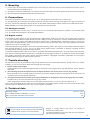
Viessmann-Formsignale haben sehr filigrane Masten. Daher sollten Sie das Signal nie am Mast anfassen, sondern immer nur an
der Bodenplatte bzw. am Antriebszylinder (Abb. 1). Bei einem Ausbau aus der Modellbahnplatte nicht oben ziehen, sondern das
Signal unter der Platte am Antriebszylinder greifen und nach oben hinausschieben!
3. Aufstellung
Schienen und Räder der Eisenbahn sind aus Stahl. Die geringe Reibung von Stahl auf Stahl bedeutet lange Bremswege. Damit
der Lokführer den Zug vor dem Hauptsignal zum Halten bringen kann, muss er früh genug erfahren, welchen Signalbegriff das
folgende Hauptsignal zeigt. Das ist Aufgabe des Vorsignals. Das Vorsignal zeigt dem Lokführer den Signalbegriff des Hauptsignals.
Signalbegriffe des Vorsignals finden Sie in Abb. 2.
Vorsignale stehen im Bremswegabstand vor dem Hauptsignal, rechts vom Gleis. Je nach Streckengeschwindigkeit beträgt der
Abstand 400 m, 700 m oder 1000 m (Abb. 3).
Der Lokführer darf Vorsignale keinesfalls übersehen. Deshalb werden sie durch Vorsignalbaken angekündigt.
Viele weitere Informationen über Signale finden Sie im Viessmann-Signalbuch, Art. 5299.
4. Funktionskontrolle
Nehmen Sie das Signal vorsichtig aus der Verpackung. Führen Sie vor der Montage eine Funktionskontrolle durch.
Schließen Sie dazu das gelbe Kabel (ohne Markierung) an einem Pol eines 16 V-Modellbahntransformators (z. B. Art. 5200) an.
Verbinden Sie abwechselnd jeweils ein blaues Kabel mit dem anderen Pol des Trafos. Schließen Sie niemals die blauen Kabel
gleichzeitig an. Das kann zur Zerstörung des Signals führen.
Das Signal schaltet in die entsprechenden Stellungen (Abb. 2):
Blau mit roter Markierung: Signal auf „Halt erwarten“ (Vr0)
Blau mit grüner Markierung: Signal auf „Fahrt erwarten“ (Vr1)
Blau mit gelber Markierung: Signal auf „Langsamfahrt erwarten“ (Vr2)

3
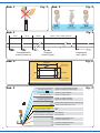
5. Einbau
1. Sägen Sie an der Montagestelle ein Loch mit den Maßen 30 mm x 15 mm. Bohren Sie dazu zuerst 4 Löcher mit 6 mm
Durchmesser. Verwenden Sie die in der Abb. 4 abgedruckte Schablone.
2. Führen Sie die Anschlusskabel von oben durch das Montageloch und stecken Sie dann das Signal mit dem Antrieb voran
hinein.
3. Befestigen Sie das Signal mit den beiliegenden Schrauben.
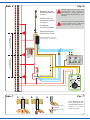
6. Anschluss
Schließen Sie nun das Signal gemäß den Abb. 6 oder 8 an. Zur Bedeutung der Kabelfarben siehe Abb. 5.
Für die Versorgung der Signalbeleuchtung empfehlen wir einen separaten Transformator. Das verhindert ein eventuelles Flackern
der Beleuchtung beim Umschalten des Signales durch den erhöhten Strombedarf des Antriebes.
Gleichstrombetrieb: Schließen Sie die beiden gelben Kabel an den Minuspol des Trafos an.
6.1 Analoge Ansteuerung
In Abb. 6 zeigen wir Ihnen, wie einfach Sie die dreibegriffigen Formsignale mit Hilfe der Viessmann Tastenstellpulte, Art. 5546
(ohne Rückmeldung) oder Art. 5548 (mit Rückmeldung durch LEDs) anschließen können. Schalter, Taster und Relais anderer
Hersteller können Sie auch verwenden.
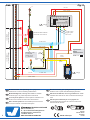
6.2 Digitale Ansteuerung
Viessmann-Formsignale können auch von einem Digitalsystem angesteuert werden (Abb. 8). Beim Anschluss z. B. an den
Viessmann Motorola-Magnetartikeldecoder, Art. 5211 (MM) müssen Sie darauf achten, dass neben den blauen Kabeln zur Sig-
nalsteuerung auch das gelbe Kabel (ohne Markierung) für die Stromversorgung angeschlossen ist. Zum digitalen Schalten eines
dreibegriffigen Signals werden 1½ Ausgangsgruppen eines Magnetartikeldecoders benötigt. Die nicht benötigte Ausgangsbuchse
kann für ein weiteres dreibegriffiges Signal verwendet werden (zusammen mit einer anderen Ausgangsgruppe) oder für ein
Entkupplungsgleis.
Viessmann-Formsignale mit 2 Antrieben benötigen positive Schaltimpulse. Daher kann man die Signale nicht ohne weiteres mit
allen Magnetartikeldecodern (z. B. von Lenz, Trix etc.) schalten, da diese Decoder negative Schaltimpulse liefern. Von Viessmann
gibt es daher für alle Digitalsysteme Decoder, welche positive Schaltimpulse liefern!
Art. 5211 (4-fach) ist kompatibel zum Märkli-Motorola-Format. Der 4-fach Multiprotokolldecoder, Art. 5280 ist als Schalt- und
Weichendecoder kompatibel zu allen DCC-Digitalsystemen wie z. B. Digital plus (Lenz), Arnold Digital, Roco Digital, Fleischmann
Twin Center, Digitrax, Uhlenbrock Intellibox, Tillig Digital, Viessmann Commander usw. und unterstützt das Märklin-Motorola-Format.
7. Fehlersuche
Jedes Viessmann Produkt wird unter hohen Qualitätsstandards gefertigt und vor seiner Auslieferung geprüft. Sollte es dennoch zu
einer Störung kommen, können Sie anhand der folgenden Punkte eine erste Überprüfung vornehmen. Testen Sie jedoch zuvor die
Stromzuführungen.
1. Scheibe oder Flügel stehen nicht gerade:
Signal auf Stellung Vr0 stellen und Scheibe / Flügel vorsichtig gerade stellen. Beide lassen sich auf ihrer Drehachse verstellen.
Unter Umständen müssen Sie die auf der Rückseite befindlichen Anschläge etwas nachrichten.
2. Das Signal schaltet hörbar, Scheibe oder Flügel bewegen sich jedoch nicht oder nur teilweise:
Hubstangen vorsichtig etwas nach oben oder unten bewegen. Eventuell die Hubstangen oben lösen und prüfen, ob die
Mechaniken sich widerstandslos bewegen lassen.
3. Die Signallampen leuchten, die Stromzuführung ist zweifelsfrei in Ordnung, das Signal schaltet aber nicht:
Der innenliegende Endabschaltungskontakt befindet sich in einer Zwischenposition. Abhilfe: Strom abschalten! Schutzkappe
unten am Signalantrieb abziehen und den Schaltkontakt mit Hilfe einer Stecknadel oder eines dünnen Drahtes einmal nach oben
bewegen (Abb. 7).
Sollte das Produkt fehlerhaft sein und Sie finden die Fehlerursache nicht, nehmen Sie bitte Kontakt mit uns auf (service@viessmann-modell.
com).Senden Sie uns den Artikel zur Kontrolle bzw. Reparatur bitte erst nach Rücksprache zu.
8. Technische Daten
Betriebsspannung: 16 V AC~ / DC=
Stromaufnahme (im Schaltmoment, ca. 0,03 s): 0,6 A
Maximale Belastbarkeit des Fahrstromkontaktes: 2 A
Änderungen vorbehalten. Keine Haftung für Druckfehler und
Irrtümer.
Die aktuelle Version der Anleitung finden Sie auf der Viessmann
Homepage unter der Artikelnummer.
Entsorgen Sie dieses Produkt nicht über den (un-
sortierten) Hausmüll, sondern führen Sie es der
Wiederverwertung zu.

4
EN
1. Important information
Please read this manual completely and attentively before using the product for the first time. Keep this manual. It is part of the
product.
1.1 Safety instructions
Caution:
Risk of injury!
Due to the detailed reproduction of the original and the intended use, this product can have peaks, edges and breakable parts.
Tools are required for installation.
Electrical hazard!
Never put the connecting wires into a power socket! Regularly examine the transformer for damage. In case of any damage,
do not use the transformer.
Make sure that the power supply is switched off when you mount the device and connect the cables!
Only use VDE/EN tested special model train transformers for the power supply!
The power sources must be protected to avoid the risk of burning cables.
1.2 Using the product for its correct purpose
This product is intended:
- For installation in model train layouts and dioramas.
- For connection to an authorized model train transformer (e. g. item 5200) or a digital command station.
- For operation in dry rooms only.
Using the product for any other purpose is not approved and is considered inappropriate. The manufacturer is not responsible for
any damage resulting from the improper use of this product.
1.3 Checking the package contents
Check the contents of the package for completeness:
- Semaphore distant signal
- 2 screws
- Manual
2. Introduction
Viessmann semaphores stand out for their prototypical slow arm movement and they are simple to mount and connect. This signal
has two electromagnetic drive units, en position switch-off and an integrated contact for train control.
Viessmann semaphores have finely detailed metal masts (fig. 1). Therefore, you should never grasp the masts but only the drive
unit for mounting or dismounting. If you have to remove the signal, do not pull the at signal mast. Carefully grasp the drive unit
instead and push it up.
3. Setting up signals
Wheels and rails of the railway are made of steel. The friction between steel and steel is very low, which results in long stopping
distances. To prevent accidents caused by the long stopping distance, distant signals were introduced. A distant signal shows the
aspect of the following main signal on the topical way. You will find the aspects of the distant signal in fig. 2.
Distant signals are put up in the stopping distance in front of the main signal. They stand on the right side of the track. Depending
on the speed limit the distance is 400 m, 700 m or 1000 m (fig. 3).
To inform the engine driver that a distant signal is ahead of him, warning beacons are put up on the right side of the track.
For more information regarding signals please refer to Viessmann signal book, item 5299 – German language.
4. Checking the function
Carefully remove the signal from the box. Check all functions prior to installation.
Connect the yellow cable to one of the terminals of a 16 V transformer (e. g. item 5200.)
Then alternately make contact between the blue cables and the other terminal, but only briefly. Never connect the blue cables
at the same time to the transformer. This may destroy the signal.
The signal switches into its respective aspects (fig. 2):
Blue with red marker: Signal on “Expect Stop” (Vr0)
Blue with green marker: Signal on “Expect Proceed” (Vr1)
Blue with yellow marker: Signal on “Expect Proceed Slowly” (Hp2)

5
5. Mounting
1) Cut a 30 mm x 15 mm hole at the installation spot. In a first step you need to drill 4 holes of 6 mm diameter each into the corners.
Use the pattern which is shown in fig. 4.
2) The signal‘s connection cables have to be inserted into the hole first. After that put the signal with the drive first into that hole.
3) Attach the signal to the baseboard with the enclosed screws.
6. Connections
Now make the electrical connection as per fig. 6 or 8. For the signification of the cable colours refer to fig. 5.
For the signal light, we recommend a separate transformer. This will prevent flickering of the lights due to high consumption of
the drive. Connect the signal light to the transformer via the yellow cable with black marker and the brown cable with the diode.
Direct current: Connect both yellow cables to the negative pole of the transfomer.
6.1 Analogue control
The conventional wiring is shown in fig. 6. It shows how you can connect the three-aspect form signals to a push-button panel
(e. g. item 5546 without feedback or item 5548 with feedback).
6.2 Digital control
The semaphore home signals can also be operated with a digital system. Refer to fig. 8 for the correct wiring. When connecting
e. g. to the Viessmann Motorola digital decoder, item 5211 (MM) you have to make sure to connect, besides the blue cables for
signal control, also the yellow cable (without marker) for power supply. To digitally switch a three-aspect signal, you need 11/2
output groups of a digital decoder. The remaining output socket can be used for another three-aspect signal (together with another
output group) or for an uncoupling track.
Viessmann semaphore signals with 2 drive units need positive switching pulses. This is why you cannot offhand switch the signals
with all digital decoders (e. g. Lenz, Trix etc.) as these supply negative pulses. Viessmann is, therefore, supplying decoders
providing positive switching pulses for all digital systems!
The Motorola digital decoder (item 5211, 4-fold) is compatible with Märklin-Motorola-format. The 4-fold multi protocol decoder,
item 5280 as a switching and turnout deocder is compatible to all DCC digital systems, e. g. Digital plus (Lenz), Arnold Digital,
Roco Digital, Fleischmann Twin Center, Digitrax, Uhlenbrock Intellibox, Tillig Digital, Viessmann Commander etc. and supports
the Märklin-Motorola format as well as the DCC protocol.
7. Trouble-shooting
All Viessmann products are produced with high quality standards and are checked before delivery. Should a fault occur notwith-
standing, you can do a first check. Begin with checking the power supply.
1. Disk or arms are not straight:
Set the signal to the Vr0 aspect and adjust the disk or arm back into the straight position very carefully! Both can be shifted on
their axles.
2. The switching sound of the signal drive can be heard, but disk or arm do not move or move only partially.
Move the lifting rod very carefully slightly up and down (if necessary detach the lifting rod from the bar lever and check if bar
mechanics can be moved without resistance).
3. The signal lamps illuminate and the power supply doubtlessly is working fine, however the signal does not switch.
Possible reason: The inner limit switch has not got any contact.
Switch off the electrical power! Then move up the switch contact by means of a pin or a thin wire (refer to fig. 7).
If the product is damaged please contact our service department ([email protected]). Please send the item to the
Viessmann service department for check resp. repair only after consultation
8. Technical data
Operating voltage: 16 V AC~ / DC=
Current draw (moment of switching, ca. 0.03 s): 0.6 A
Max. contact load of the track control contact: 2 A
Subject to change without prior notice. No liability for
mistakes and printing errors.
You will find the latest version of the manual on the Viessmann
website using the item number.
Do not dispose of this product through (unsorted)
domestic waste, supply it to recycling instead.

6
Fig. 1
Abb. 1 Fig. 2
Abb. 2
Halt erwarten
expect stop
Fahrt erwarten
expect proceed
Langsamfahrt erwarten
expect proceed slowly
Vr0 Vr2 Vr1
75 m 400 m, 700 m oder 1000 m100 m75 m
Vorsignalbaken HauptsignalVorsignal
warning beacons main signaldistant signal
Fig. 3
Abb. 3
30 mm
15 mm
Ø 6 mm
Ø 1,4 mm
blau mit roter Markierung
blue with red mark
blau mit grüner Markierung
blue with green mark
gelb + Widerstand / Markierung
yellow + resistor or mark
gelb
yellow
braun (+Diode bei LED-Licht)
brown (+diode for LED lighting)
rot
red
rot
red
Signal Vr0 (Halt erwarten)
signal Vr0 (expect stop)
Signal Vr1 (Fahrt erwarten)
signal Vr1 (expect proceed)
gemeinsamer Mittelpunkt der Antriebsspulen
common pole for the drive coils
Licht
light
Licht (Masse)
light (ground)
Kontakt für Zugbeeinflussung
contact for train control
Kontakt für Zugbeeinflussung
contact for train control
blue with yellow mark
Signal Vr2 (Langsamfahrt erwarten)
signal Vr2 (expect proceed slowly)
blau mit gelber Markierung
Fig. 5Abb. 5
Fig. 4
Abb. 4

7
Tasten - Stellpult
5548
Viessmann
Überlast
Eingang Ohm 15/20
10 Ohm 30 Ohm
viessmann
5216
Langsamfahrwiderstand
Steuermodul. Nicht entfernen!
Control module. Do not remove!
ca. 2 Loklängenca. 1,5 Zuglängen
ca. two locomotive lengthsca. 1,5 locomotive lengths
z. B. / e. g.
5216
Beachten Sie die
Anschlusshinweise
in Kap. 6.
Observe the con-
necting instructions
in chap. 6.
Dieses Symbol neben dem Gleis
kennzeichnet eine Trennstelle
(Gleichstrom = rechte Schiene in
Fahrtrichtung, Wechselstrom = Mit-
telleiter).
This sign next to the track indicates
a track insulation (DC = right rail in
driving direction, AC = third rail).
Formsignal
mit zwei Antrieben.
Semaphore signal
with two drive units.
Fig. 6Abb. 6
Fig. 7
Abb. 7
Nadel oder dün-
ner Draht
Needle or thin
wire
Diese Maßnahme darf
nur im stromlosen Zu-
stand ausgeführt werden!
Switch off power
before doing this!
1. 2. 3.

Modellbauartikel, kein Spielzeug! Nicht geeignet für
Kinder unter 14 Jahren! Anleitung aufbewahren!
Model building item, not a toy! Not suitable for children
under the age of 14 years! Keep these instructions!
Ce n’est pas un jouet! Ne convient pas aux enfants de moi-
ns de 14 ans! Conservez cette notice d’instructions!
Não é um brinquedo! Não aconselhável para menores de
14 anos! Conservar o manual de instruções!
Modelbouwartikel, geen speelgoed! Niet geschikt voor
kinderen onder 14 jaar! Gebruiksaanwijzing bewaren!
Articolo di modellismo, non è un giocattolo! Non adatto
a bambini al di sotto dei 14 anni! Conservare istruzioni per
l’uso!
Artículo para modelismo ¡No es un juguete! No
recomendado para menores de 14 años! Conserva las
instrucciones de servicio!
DE
EN
FR
NL
IT
ES
PT
Made in Europe
Viessmann
Modelltec
hnik GmbH
Bahnhofstraße 2a
D - 35116 Hatzfeld-Reddighausen
+49 6452 9340-0
www.viessmann-modell.de
8
Fig. 8
Sekundär
0-10-16 V~
16 V
Primär
230 V~
Gefertigt nach
VDE 0570
EN 61558
Lichttransformator
5200
Nur für trockene Räume
Primär 230 V 50 - 60 Hz
Sekundär max. 3,25 A52 VA
ta 25°CIP 40
10 V
0 V
rt bn rt 1 gn rt 2 gn
ON
1 2 3 4 5 6 7 8
WP
Viessmann
5211
Magnetartikeldecoder
rt bn E gn 4 rt gn 3 rt
braun
gelb
z. B.
5211
Steuermodul. Nicht entfernen!
Markierung
16 V ~ / =
Digitalzentrale
z. B.
5200
gelb
ca. 2 Loklängen ca. 1,5 Zuglängen
Widerstand 1,5 kΩ
z. B. Art. 6836
rot
braun / brown
braun / brown
gelb / yellow
braun / brown
yellow
Control Unit. Do not remove!
/ e. g.
brown
mark
Digital
command station
/ e. g.
yellow
ca. two locomotive lengthsca. 1,5 locomotive lengths
Resistor 1.5 kΩ
e. g. item 6836
red
rot / red 3 x blau / blue
3 x blau / blue
rot / red
grün / green
rot / red
Abb. 8
Points de collecte sur www.quefairedemesdechets.fr
À DÉPOSER
EN MAGASIN À DÉPOSER
EN DÉCHÈTERIE
OU
Cet modéle
se recycle
FR
FR
98478
Stand 05/sw
03/2023
Ho/Kf
-
 1
1
-
 2
2
-
 3
3
-
 4
4
-
 5
5
-
 6
6
-
 7
7
-
 8
8


in altre lingue
- English: Viessmann 4511 Owner's manual
- Deutsch: Viessmann 4511 Bedienungsanleitung
Documenti correlati
-
Viessmann 5548 Manuale del proprietario
-
-
-
-
-
-
-
-
-