
XP2i
Operation Manual
for XP2i Digital Test Gauge (Standard and Dual-Display(DD))

Contents
Overview ............................................................. 1
Introduction .......................................................... 1
Operating Instructions ................................................. 2
Functions ............................................................ 3
Data Logging with DataLoggerXP .......................... 10
What is DataLoggerXP? ............................................... 10
Installing the Software ................................................ 12
Authorizing a Gauge .................................................. 12
DataLoggerXP Software Operation .................................... 13
XP2i DataLoggerXP Gauge Operation .................................. 18
Excel Templates ...................................................... 22
Enclosure ............................................................ 23
Serial Numbers ....................................................... 24
Specifications ...................................................... 25
Power ................................................................ 27
Pressure Ranges, Display Scales, & Resolution .......................... 28
Part Numbering System ............................................... 28
Safety & Certifications .......................................... 29
Hazardous Locations .................................................. 29
Certications ......................................................... 29
ATEX/IECEx Safety Instructions ........................................ 30
Support .............................................................. 35
Troubleshooting ...................................................... 35
Calibration . . . . . . . . . . . . . . . . . . . . . . . . . . . . . . . . . . . . . . . . . . . . . . . . . . . . . . . . . . . 36
Software ............................................................. 37
Replacement Parts .................................................... 37
Accessories ........................................................... 37
Contact Us ........................................................... 38
Factory Service ....................................................... 38
Trademarks .......................................................... 38
Warranty ............................................................. 38

Overview 1
XP2i Operation Manual
Overview
INTRODUCTION
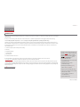
Thank you for choosing the XP2i Digital Test Gauge from Crystal Engineering Corporation. Your XP2i is a combination of leading edge technology and rugged
industrial design.
Accuracy is 0.1% “of reading”, 0.02% “of Full Scale” or 0.05% “of Full Scale”
–
so any XP2i can typically replace several gauges you may have been using.
The XP2i is fully temperature compensated
–
so there is no change in accuracy throughout the entire operating temperature range!
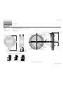
The XP2i’s case is made from rugged aluminum alloy utilizing a gasket to seal the enclosure against dust and water intrusion. Even the RS-232 connector is
fully sealed (with or without the red cover or rubber boot). Circuitry is mounted in shock absorbing elastomer supports and the batteries are easily accessible
by removing four screws. But you won’t need to change the batteries often, since 3 AA batteries operate the XP2i for up to 1500 hours of continuous use.
Other features include:
•
Continuous capture of peak and valley pressure readings
•
PSV mode
•
Programming interface
•
User-dened units
•
Intrinsically Safe
•
All welded 316 stainless steel sensor
We hope your XP2i meets your expectations, and we're interested in any comments or suggestions you may have. You can send us a note at:
[email protected]. Many features in this and our other products are a direct result of your comments!
C
rystal Engineering is the company that designs, manufactures, markets, and services the nVision reference pressure recorder, XP2i, and 30 Series pressure
calibrators, M1 Pressure Gauge, MultiCal multimeter pressure adapters, and a variety of industry specic pressure measuring equipment. Crystal Engineering
pioneered features like full temperature compensation and “of reading” rated gauges and calibrators. Pressure measuring equipment is the only thing we do
and that’s why we say:
™
Your XP2i can be customized, through the use
of our free CongXP™ software. Your personal
computer can disable, enable, or modify a
variety of features of your XP2i. Look for the
logo for
programmable features, like:
•
A user dened pressure scale, and/or disable
unused pressure units
•
Password protection to prevent
unauthorized changes
•
Disable keypad recalibration, (peak)
button, and/or
(units) button
•
Expand or decrease allowable Zero range
•
Set the gauge to a dierent density of water
factor (4° C, 60° F, or 68° F)
•
Store a 12 digit ID or tag number in
non-volatile memory
•
Adjust calibration values

Overview 2
XP2i Operation Manual
OPERATING INSTRUCTIONS
The XP2i is shipped with batteries installed, so it’s ready to use. Press and hold the (on/o) button. The XP2i will rst test all LCD segments. Release
the
(on/o) button when the XP2i indicates pressure.
The XP2i always resumes operation in the mode and the units of the pressure last used, and it does not automatically rezero when turned on.
Connect the XP2i to your system.
!
CAUTION: Use a wrench (¾" or 19mm) for installation and removal of XP2i! There is a limit to how much rotational force can be applied to the case, so
don’t rely on, or use, the case to screw the XP2i into a tting, and don’t use the case to remove the XP2i tting, either.
!
CAUTION: Never insert any object into the pressure connection! The sensor diaphragm is very thin and can be damaged or destroyed by solid or sharp
objects. Cleaning of the sensor must be done with appropriate solvents only.
!
WARNING: Severe injury or damage can occur through improper use of pressure instruments! Do not exceed recommended pressure limits of tubing
and ttings. Be certain all pressure connections are secured.
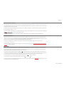
Most XP2i’s are intended for gauge pressure measurement. That is, they indicate the dierence between applied pressure and ambient barometric pressure.
However, the
(zero) button can be used to force an XP2i to read zero pressure at any applied pressure, up to the full scale rating of the gauge. The factory
default setting limits the maximum zero value to 20 psi, but this limit can be changed with
.
Some XP2i’s are rated for absolute pressure. Absolute gauges indicate the dierence between applied pressure and an internal vacuum reference. Absolute
pressure is always positive. For instance barometric pressure at sea level is on average about 14.7 psi (approximately 100 kPa or 1 bar), so at sea level this is the
lowest expected pressure indication. However, absolute gauges can be “zeroed” (unless prevented by CongXP). After zeroing an absolute gauge it is possible
to indicate a negative or positive gauge pressure.
!
WARNING: This gauge can display zero pressure when connected to a source of pressure! Do not rely on the display indication before disconnecting—
it may not be indicating true pressure. Never disconnect pressure instrumentation without rst relieving system pressure!

Functions 3
XP2i Operation Manual
Functions
units
Units Button
Pressing this button causes the XP2i to select the next available unit of pressure measurement.
See Pressure Ranges, Display Scales, & Resolution on page 28 or the list of pressure units available for your model.
Units that you don’t need or never use can be turned o. You can also dene a special unit for your XP2i with CongXP. You can
use the XP2i to display directly in a unit not otherwise available, such as feet of seawater, or foot-pounds of torque. When you select your custom unit from the
keypad, the screen displays the USER icon.
Hi
Lo
peak
Peak Button
On the XP2i, pressing the (peak) button causes the display to cycle
through the following , depending on your setting in CongXP.
<No Icon> . . . . Live Pressure display
. . . . Maximum detected pressure
. . . . Minimum detected pressure
(blinking)
. . . . PSV Mode, maximum
*
(blinking)
. . . . PSV Mode, minimum
*
. . . .
Average pressure
. . . . DataLoggerXP datalogging mode
* From the factory this setting is disabled. Use CongXP to enable.
Peak High and Peak Low values are not saved when the gauge shuts o; they will reset to the current
reading when the XP2i is turned on or reset.
In some cases the ability to display a peak value may not be needed, or
may even be dangerous. CongXP allows you to disable this button.
XP2is can average 1 to 10 readings, recalculated every time pressure is measured (4 times per second).
Enable and set the number of readings to be averaged with CongXP.
On the -DD, dual-line display XP2i, pressing the
(peak)
button causes the display to cycle
through the following, depending on your setting in CongXP:
<No Icon> . . . . Live Pressure display
. . . . Maximum detected pressure
. . . . Minimum detected pressure
(blinking)
. . . . PSV Mode maximum
*
(blinking)
. . . . PSV Mode minimum
*
. . . . Average pressure
. . . . DataLoggerXP datalogging mode
(remaining points displayed on lower line)
. . . . Tare
*
. . . . Rate of change
*
. . . . Dierential Mode
*
+
. . . . Average Dierential Mode
*

Functions 4
XP2i Operation Manual
clear
zero
Resetting (Clearing) Recorded Peak Values
Peak values can only be cleared when displaying either a Peak High or Peak Low recorded pressure. Press the (clear) button for at least ½ second. Dashed
lines will briey appear across the display indicating that both Peak values have been cleared. Both Peak High and Peak Low values will then display the cur-
rent applied pressure. Pressing the
(clear) button while either the Peak High (
HI
) or Peak Low (
LO
) icon is displayed will not aect the zero value. If you
need to rezero the gauge, you must turn o both peak icons by pressing the
(peak) button.
clear
zero
Zero
If you attempt to zero the gauge while applying a pressure which exceeds the Zero Limit (set in CongXP, defaults to 20 psi),
the command will be ignored and “--HI-” will be displayed.
X
To Zero the XP2i
Turn o peak indication by pressing the (peak) button repeatedly until the HI and LO icons are o, then press the (zero) button for at least ½ second when
the gauge is vented to atmosphere.
The display will then briey ash all dashed lines (
), indicating that it has been re-zeroed. Absolute gauges will now indicate gauge pressure.
!
WARNING: This gauge can display zero pressure when connected to a source of pressure! Do not rely on the display indication before disconnecting—
it may not be indicating true pressure. Never disconnect pressure instrumentation without rst relieving system pressure!
X
To Clear the Zero Value on an XP2i
Turn o peak indication as described above, then press and hold the (zero) button until the display changes from (
) to (
).
This is especially useful for absolute gauges that have been zeroed to use for gauge pressure measurement.

Functions 5
XP2i Operation Manual
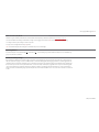
Tare
(
-DD, Dual-Line Display XP2i Only
)
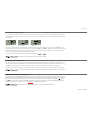
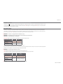
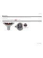
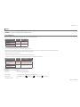
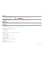
Tare is a constant value subtracted from the true pressure. For instance, if you were mixing gases by partial pressure, you might want to ll a tank to 1760 psi
with air, then add another 440 psi of helium. To reduce the chance of error, you could tare the gauge at 1760 psi. Then you would add helium until the indica-
tion reached 440.
PSI
TARE
PSI
TARE
PSI
TARE
Fill to pressure Press the Tare button Top-o with helium
In contrast to the Zero function discussed previously, Tare is not subject to the Zero Limit set in CongXP. Tare is available only when the TARE icon is on. To
use the Tare feature, press the
(peak) button repeatedly until the screen displays the TARE icon. The TARE icon will ash to remind you that live pressure may
not be indicated on the screen. Apply pressure to the gauge until you reach the desired value. Press the
(zero) button. The top line will change from true
pressure to zero. The amount of the tare will be displayed on the second line.
To clear the tare, press and hold the
(zero) button until the tare value changes from (
) to (
).
The Tare function is disabled by default, but can be enabled with CongXP.
Rate
(
-DD, Dual-Line Display XP2i Only
)
Rate is the measurement of pressure change per minute. When in Rate mode, the second line will display the rate, and the /min icon will display. Rate is
calculated at every pressure measurement (4 times per second), and the displayed value is the average of the most recent 3 to 10 calculations. By increasing
the number of calcula
tions in the average, the XP2i will indicate a more stable rate. However, the XP2i will react more slowly to changes in rate.
To use the rate feature, press the
(peak) button repeatedly until the /min icon displays. As pressure changes, the second line will indicate rate of change.
The rate function is disabled by default, but can be enabled and congured with CongXP. The number of calculations can also
be set with the digital interface.
Dierential Mode
(
-DD, Dual-Line Display XP2i Only
)
Dierential mode allows the XP2i-DD gauge (the master) to be connected to a second XP2i or XP2i-DD gauge (the slave) and display the pressure dierence
between the two gauges. A standard RS232 cable (p/n 2400) and null modem adapter (p/n 3456) or a null modem cable are required to directly connect the
gauges. You must use CongXP to enable this feature, and once enabled, use the
(peak) button on the master gauge until the Peak High (
HI
) and Peak
Low (
LO
) icons are displayed simultaneously. An XP2i-DD gauge must be running rmware version R0114 or later, and an XP2i gauge must be running
rmware version R0014 or later for this feature to work. Use XP2iUpdate to upgrade to the latest rmware.
The dierential mode is disabled by default, but can be enabled and congured with CongXP.

Functions 6
XP2i Operation Manual
Automatic Shut-o
The XP2i has a shuto timer and will turn o automatically after 20 minutes of non-operation. Pressing any button or sending any command via the RS-232
connection resets the shuto timer for another 20 minutes of operation. The XP2i will briey display Auto O 20 when turned on.
To disable the shuto feature, turn on the XP2i by pressing the
(on/o) and (zero) buttons simultaneously. The XP2i will briey display the words No Auto
O to indicate that it will not turn o. The shuto feature can be enabled again when turning the XP2i on, by pressing the same
(on/o) and (zero) buttons.
These settings are retained when the product is powered down.
Note: This key combination will not toggle the auto-shuto feature if CongXP is set to require a password before changing settings.
Backlight
Pressing the (backlight) button instantly lights the display at maximum brightness. Hold down the button for 1 second to keep it on. The display will ash
briey, indicating that it will stay on for 1 minute. If you press the
(backlight) button again, the backlight will go into a lower brightness setting to extend bat-
tery life, and remain on for 2 minutes after the last key is pressed. Press the
(backlight) button once more and the light will go out.
If you start the XP2i in the No Auto O mode, you may select the brightness level in the same way. The light will never time out and turn o. Turn o the XP2i,
or press the
(backlight) button repeatedly, to turn o the backlight.
Measuring Vacuum
All versions of the XP2i can be used to measure moderate vacuum, though only ranges of 300 psi (and 20 bar or 2000 kPa) and lower are actually tested and
certied for vacuum operation.
When measuring pressure less than ambient barometric conditions, a minus (-) sign will appear.
Absolute gauges (models with a “B” in front of “XP2i” in the part number) will NOT indicate a negative sign when vacuum is applied, unless the
(zero) button
has been pressed while a pressure greater than full vacuum is applied to the gauge. If your absolute gauge does indicate a negative pressure, you can clear
the zero value (“unzero”) by pressing the
(zero) button until the display changes from (
) to (
).
!
CAUTION: XP2is are not recommended for continuous use below -14.5 psig.
For continuous use below -14.5 psig with high accuracy, choose our XP2i-DP Dierential Pressure Gauge.

Functions 7
XP2i Operation Manual
Water Density (Inches of Water)
The following applies only to models where inches of water is a selectable pressure unit. As shipped from the factory, the XP2i is set to display inches of water
corresponding to the density of water at 4° C (39.2° F). You may require a dierent water density for your application, so the XP2i can be set to use the density
of water at 20° C (68° F) or 15.6° C (60° F) instead.
To check and/or change the water density setting from the keypad, turn on the XP2i by pressing the
(on/o) button and the (peak) button simultaneously.
The display will indicate either 4C, 60F, or 68F.
Press the
(units) button until the display cycles to the desired water density, then press the (zero) button to store the selection (this will not zero the gauge).
Select and set the desired density of water.
Note: If the XP2i is password protected, or inches of water is disabled, you will not be able to view or change the water density from the keypad.
Overpressure Conditions
The XP2i will read pressure up to approximately 110% of the rated pressure range. Above 110% percent of the range the display will start ashing and the
readings will not be reliable. The zero function does not aect the point at which the display starts ashing to indicate overpressure, so depending on the zero
value it is possible that the display can start ashing without the maximum pressure being displayed.
For instance, if a 100PSIXP2i is zeroed when 30 psi is being applied, it will indicate that the overpressure condition has been reached at 80 psi
(i.e., 110% x 100 psi – 30 psi = 80 psi).
O
verpressure can aect accuracy, but the eect is only temporary unless the sensor has been destroyed. See Pressure Ranges, Display Scales, & Resolution
on page 28 for maximum overpressure.
PSVtest Mode
PSVtest mode is designed for PSV and PRV (“Pressure Safety Valve” and “Pressure Relief Valve”, respectively) as well as for Rupture Disc (also known as “Burst
Disc”) testing. It increases the measurement rate of the XP2i gauge to approximately eight times per second, to capture the peak pressure when the valve
opened, and adds a method of automatically capturing the closing reseat pressure.
Use CongXP to activate PSVtest Mode. When the Peak High icon (
HI
) ashes, PSVtest mode is enabled. A special feature of PSVtest is that Peak Low
is au-
tomatically reset to the Peak High value whenever a new Peak High value is detected. Once pressure stops increasing, as when a PSV opens (and the pressure
dr
ops below the maximum pressure) XP2i detects the new minimum pressure values (the Peak Low), capturing the closing pressure of a PSV.
Press the
(peak) button once to view the captured reseat pressure. The Peak Low icon (
LO
) will ash on the display.
To clear the peaks, press the
(clear) button while the display shows the High (
HI
) or Low (
LO
) icons.
Application note AN-006
–
Pressure Safety Valve Testing detailing the operation of the PSVtest mode is available on our website, and includes examples on how
to use the gauge in relief valve and burst disk testing.

Functions 8
XP2i Operation Manual
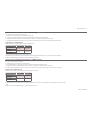
Low Battery Indication
The Battery icon ( ) uses three bars to display the battery level. When the icon displays all three bars, the batteries are full. The XP2i will continue to operate
accurately while the icon is visible. When the batteries are exhausted, the letters batt will appear across the display. After batt appears, no pressure measure-
ments will be possible until the batteries are replaced.
Battery Replacement
The XP2i uses 3 AA batteries. Loosen the four rear panel screws to gain access to the battery compartment. These four panel screws are captive inside the
panel and are not removable. Pull the panel up to expose the battery compartment. After replacing the batteries, the XP2i will start operating immediately
(without having to press the
(on/o) button). This indicates that a complete reset has occurred, and is normal.
!
WARNING: Do not remove or change the batteries in hazardous locations.
!
WARNING: T4 or T3 Temperature Class is based on selection of approved battery. See the table below.
!
CAUTION: Do not mix battery types or manufacturers.
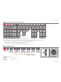
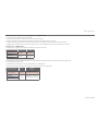
ATEX/IECEx: The XP2i is Intrinsically Safe only if powered by one of the following battery types:
Approved Battery Type Ta= Marking
Rayovac Max Plus 815
-20 to 50° C Ex ia IIC T4 Ga
Energizer E91
*
Energizer EN91*
-20 to 50° C Ex ia IIC T3 Ga
Duracell MN1500
*
Energizer is manufactured by Energizer Holdings, Inc., and the Eveready Battery Company, Inc.
Many other battery types and models have been tested but failed to meet the requirements for Intrinsic Safety—do not assume other models are equivalent.
The XP2i can be operated from an external power supply (AC adapter kit PN: 2984).
!
WARNING: Do not use AC adapter in hazardous locations.
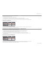
CSA: The XP2i is Intrinsically Safe only if powered by one of the following battery types:
CSA: The XP2i est un système à sécurité Intrinsèque seulement s’il est alimenté par un des Piles de type suivant:
Approved Battery Type
(Approuvé Type de Batterie)
Ta=
Marking
(Marquage)
Rayovac Max Plus 815 -20 to 45° C
Class I, Division 1, A, B, C, D T4
(Classse I, Division 1, A, B, C, D T4)
Energizer E91
-20 to 50° C
Class I, Division 1, A, B, C, D T3C
(Classse I, Division 1, A, B, C, D T3C)
Energizer EN91
Rayovac Max Plus 815
!
WARNING: Use of Duracell MN1500 batteries is not approved for CSA certication.

Functions 9
XP2i Operation Manual
Reset
If for some reason the XP2i needs to be reset, remove any battery for at least one minute, then reinstall the battery. If the reset is successful, the XP2i will
start operating without pressing the
(on/o) button. Reset will clear the zero, peak values will be reset to the current reading, and the XP2i will be set to the
default engineering units.
!
WARNING: Do not remove or change the batteries in hazardous locations.
Communications/Programming
The XP2i responds to a query-based command language which allows remote control of the gauge. Please refer to the XP2i Programming Instructions for
documentation of this feature.

Data Logging with DataLoggerXP 10
XP2i Operation Manual
Data Logging with DataLoggerXP
WHAT IS DATALOGGERXP?
DataLoggerXP is an optional data logging mode available for the XP2i gauge. You may purchase the DataLoggerXP option with your original order
or add it later.
W
ith the XP2i’s long battery life, and Ultra Low Power (ULP) mode, you can log data over an entire year, without the need for external power supplies or
battery replacements.
D
ownload the DataLoggerXP software from the Crystal website and use it to save the data recorded on your XP2i.
Note: An evaluation mode allows you to record 100 data points before requiring purchase.
With an XP2i and DataLoggerXP you can:
•
Record up to 32 000 pressure measurements (data points) into non-volatile ash memory.
•
Save battery life and record over an entire year with Ultra Low Power (ULP) mode.
•
Change data collection parameters, with or without a computer.
•
Start and stop multiple collection runs from the keypad.
•
Record pressure readings at intervals as fast as once per second or as slow as once every 18 hours.
•
Record the averages, averages and peaks, or just the pressure indication.
•
Store an indicated pressure by pushing one button.
•
View the data on any Windows-equipped computer.
•
Save the data les directly into Microsoft® Excel spreadsheets (requires Excel 2003, 2007, or 2010), or as comma separated text les.

Data Logging with DataLoggerXP 11
XP2i Operation Manual
DataLoggerXP Terminology
Clear. . . . . . . . . . . . . . . . . . . . . Removes all stored data from the XP2i memory. Individual runs cannot be removed.
Download . . . . . . . . . . . . . . . The act of copying stored data from the XP2i to a computer using DataLoggerXP software.
Events . . . . . . . . . . . . . . . . . . . Non-data readings, optionally displayed as part of a run. These include tare values, low battery indications, or logging parameters.
Logging Interval . . . . . . . . . The time, in seconds, between each data point.
Logging Type . . . . . . . . . . . . The type of data stored for each reading.
Logging Parameters . . . . . The Logging Interval and Logging Type are referred to, in this document, as the Logging Parameters.
Run . . . . . . . . . . . . . . . . . . . . . . A set of one or more readings taken by the XP2i. The user can specify dierent logging parameters for each successive run.
Note: A maximum of 64 runs can be stored in memory.
Typical Usage
While there are a variety of ways in which the DataLoggerXP software and XP2i can be used, a typical way to use the DataloggerXP
might be like this:
1
Set the logging parameters
–
either with DataLoggerXP software or directly from the keypad.
2 Enable data logging mode (the Record icon (
) will illuminate).
3 Take a recording.
4 Use DataloggerXP software to download your data into an Excel worksheet or a text le.

Data Logging with DataLoggerXP 12
XP2i Operation Manual
INSTALLING THE SOFTWARE
DataLoggerXP can either be installed from a CD provided by Crystal Engineering, or downloaded from the Crystal Engineering website.
We recommend you check the website for the latest version.
Installing from the CD
Run the Setup.exe application located on the install CD. This is typically D:\Setup.exe, but may be dierent on your computer.
Installing from the Internet
Visit ametekcalibration.com and select the DataLoggerXP software page to download the latest version of the software.
Once the setup application begins, follow the on-screen prompts to complete the installation. If DataloggerXP is being upgraded, the prior version does not
need to be uninstalled, as the new version will be installed over any existing version.
AUTHORIZING A GAUGE
The gauge must be authorized using a purchased authorization key to obtain the full 32 000 data point recording capability. The key is specic to a gauge’s
serial number, and can only be used with the gauge it was meant to authorize.
To Authorize a Gauge
1 Connect the gauge to your computer.
2 From the File menu, choose Authorize Gauge to start the Authorization Wizard.
3 Follow the on-screen instructions.

Data Logging with DataLoggerXP 13
XP2i Operation Manual
DATALOGGERXP SOFTWARE OPERATION
As described in the prior section, the DataLoggerXP application provides complete control of the settings for data logging mode on the XP2i. You can change
logging parameters and download data using the application. In this section, you will nd a description of each of the functional areas of the application.
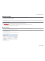
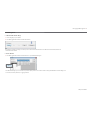
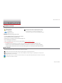
The DataLoggerXP Main Window
Working in the Main Window
X
Setting the Options
By default, DataLoggerXP is congured for automatic serial port detection. However, in some cases automatic serial port detection may not work.
To select a specic serial port, open the Options dialog box, by choosing View
> Options. Select the serial port and press OK to save any changes.
If your installation supports additional langauges, you can choose the language from the Select Language drop-down list. The settings for Excel templates
are covered in Excel Templates on page 22.

Data Logging with DataLoggerXP 14
XP2i Operation Manual
X
To Connect to the Gauge
1 Plug the serial cable into the computer and XP2i gauge ports.
2 In the DataLoggerXP main window, click Connect.
The program will retrieve the current logging parameters, and then allow downloading, viewing, and saving data, as well as updating the logging
parameters.
X
Password Protection
The password protection feature of the gauge allows you to prevent unauthorized changes to the data logging parameters. Once the password is set, the
Send to Gauge button will require the password. Changing logging parameters and Auto-O settings through the keypad will be disabled. Passwords can
only be set or removed using DataLoggerXP or CongXP. In the event you lose the password, you will need to contact the factory for an unlock code, which
will remove the password protection. To set a password:
1 In the DataLoggerXP main window, click the Set Password button.
2 In the Change Password dialog box, enter and conrm your password and click OK.

Data Logging with DataLoggerXP 15
XP2i Operation Manual
Data Logging Parameters
Logging parameters can be set up one of two ways: on a computer connected to an XP2i, or from the XP2i keypad. This second option allows the user to make
changes in the logging parameters while in the eld. Once the logging parameters have been selected, the gauge can begin recording data. The two param-
eters that aect data logging (logging interval and logging type) are covered below.
X
Logging Interval
The logging interval controls how frequently the gauge takes a measurement. XP2i data logging features a minimum recording time of 1 second and a
maximum recording time of 18 hours.
X
To Choose a Logging Type
From the Logging Type drop-down list, choose a logging type.
The gauge may operate in ve logging types:
•
Actual: The gauge stores the value displayed on the gauge at each logging interval.
•
Average: The gauge calculates and stores the average of all readings taken (4 per second) during each logging interval. For example, if the recording interval
is 10 seconds, the logged value is the average of the last 40 readings (10 seconds x 4 readings/second).
•
Average with Peaks: The highest and lowest value of each logging interval is recorded along with the average value.
•
On Demand: This mode diers from the other three, in that the logging interval does not apply. Press the (peak) button to store the displayed pressure
value and the current timestamp.
•
Actual-ULP: Similar to Actual; Ultra-Low Power mode extends recording time to over an entire year on one set of batteries. The gauge will display ULP
instead of the live pressure. Stop the recording to view the live pressure display.

Data Logging with DataLoggerXP 16
XP2i Operation Manual
Data Management
X
To Download Data from the Gauge
1 Connect the gauge to your computer.
2 In the DataLoggerXP main window, click the Download button.
Depending on the number of readings, it can take up to 15 seconds to download all the data. Once the data has been downloaded, the View and
Save buttons will be available.
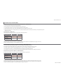
X
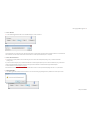
To View a Data Run
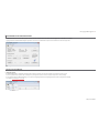
In the DataLoggerXP main window, click the View button to open the Data View dialog box.
In the Data View dialog box, you can select the run you wish to display, and choose to include or exclude recording events. Events are non-data readings, such
as tare values, low battery indications, or logging parameters.

Data Logging with DataLoggerXP 17
XP2i Operation Manual
X
To Save a Data Run
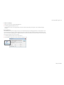
In either the DataLoggerXP main window or the View Data dialog box, click the Save button.
Save button in the DataLoggerXP main window.
Save button in the View Data dialog box.
You may download one recording run at a time. Each run will be saved to a separate le. The application will rst ask for which data run to save, and then the
name of the le to save. A le can be saved as either an Excel workbook or comma separated text le (”.txt” or “.csv”) format.
X
To Save a File in Excel Format
From the Save as type dropdown box in the Save As dialog box, choose either an Excel template le (ending in “.xlt”), or an Excel workbook le
(ending in “.xls”).
I
f you choose the Excel template (“.xlt”) a new Excel document will be created using that template. If you choose the Excel worksheet (“.xls”), you must have
already selected the default Excel template in the Options dialog box. The Excel le will be created and saved using this default template.
For more information, see Excel Templates on page 22.
I
f the le name does not include a “.xlt” or “.xls” extension, the data will be saved as a comma separate text le (ending either “.txt” or “.csv”) of that name.
X
To Clear All Data Runs
In the DataLoggerXP main window, click the Clear button to erase all runs from the gauge, making all memory available for the next sequence of runs.

Data Logging with DataLoggerXP 18
XP2i Operation Manual
XP2I DATALOGGERXP GAUGE OPERATION
When in data logging mode, XP2i provides data logging capability along with many of the features of a standard XP2i. In order to allow operation as a data
logger, some of the standard functionality of the standard XP2i is suspended.
Maximum Number of Readings
An XP2i with the authorized DataLoggerXP option can record up to 32 000 data points. By holding down the (units) button you can see the number of avail-
able data points on the gauge after the status is displayed. To avoid starting a recording, release the
(units) button after you see the number of available
points. The Dual Display (-DD) XP2i will display the number of available points on the second line, anytime data logging mode is selected.
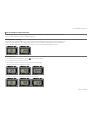
Recording Pressure
1 Press the (peak) button repeatedly until the record icon ( ) illuminates in the top left corner.
2 Connect the gauge to the pressure line to be monitored.
3 Press and hold the
(units) button on the gauge until it says Start—data is now being logged.
The units icon will blink to indicate a logging run is in progress.
The gauge displays the current state, then the number of data points available, and then the new state.
4 Once the test is complete, press and hold the (units) button again until it says Stop.
La pagina si sta caricando...
La pagina si sta caricando...
La pagina si sta caricando...
La pagina si sta caricando...
La pagina si sta caricando...
La pagina si sta caricando...
La pagina si sta caricando...
La pagina si sta caricando...
La pagina si sta caricando...
La pagina si sta caricando...
La pagina si sta caricando...
La pagina si sta caricando...
La pagina si sta caricando...
La pagina si sta caricando...
La pagina si sta caricando...
La pagina si sta caricando...
La pagina si sta caricando...
La pagina si sta caricando...
La pagina si sta caricando...
La pagina si sta caricando...
La pagina si sta caricando...
-
 1
1
-
 2
2
-
 3
3
-
 4
4
-
 5
5
-
 6
6
-
 7
7
-
 8
8
-
 9
9
-
 10
10
-
 11
11
-
 12
12
-
 13
13
-
 14
14
-
 15
15
-
 16
16
-
 17
17
-
 18
18
-
 19
19
-
 20
20
-
 21
21
-
 22
22
-
 23
23
-
 24
24
-
 25
25
-
 26
26
-
 27
27
-
 28
28
-
 29
29
-
 30
30
-
 31
31
-
 32
32
-
 33
33
-
 34
34
-
 35
35
-
 36
36
-
 37
37
-
 38
38
-
 39
39
-
 40
40
-
 41
41


in altre lingue
- English: CRYSTAL XP2i Operating instructions
Altri documenti
-
Adesso 2083P Istruzioni per l'uso
-
UNILITE ATEX-RA2 Manuale utente
-
sauter TN-EE Manuale utente
-
Omega HHP-2000 Series Manuale utente
-
Eurotherm 3200 Guida utente
-
Crowcon T4 Manuale utente
-
 LR 2000 Serie Manuale utente
-
Crowcon Gas-Pro Istruzioni per l'uso
-
WIKA CPC6050 Istruzioni per l'uso
-
Varian Saturn 2000 GC/MS Manuale utente
