
512CH. DMX CONTROLLER English
Türkçe
PILOT 2000

2
GB
appendix
IDFE
Pilot2000 version 1.32
General instructions
Read the instructions in this handbook carefully, as they give important information regarding
safety during installation, use and maintenance.
Be sure to keep this instruction manual with the unit, in order to consult it in the future. If the
unit is sold or given to another operator, make certain that it always has its manual, to enable
the new owner to read about its operation and relative instructions.
- This unit is not intended for home use.
- After having removed the packaging, check that the unit is not damaged in any way. If in doubt,
don't use it and contact an authorized SSP Technical Service Centre.
- Packaging material (plastic bags, polystyrene foam, nails, etc.) must not be left within children's
reach, as it can be dangerous.
- This unit must only be operated by adults. Do not allow children to tamper or play with it.
- Electrical work necessary for installing the unit must be carried out by a qualified electrician or
experienced person.
- Never use the unit under the following conditions:
- In places subject to excessive humidity
- In places subject to vibrations or bumps.
- In places with a temperature of over 45°C or less than 2°C
- Protect the unit from excessive dryness or humidity (ideal conditions are between
35% and 80%).
- Do not dismantle or modify the unit.
- Make certain that no inflammable liquids, water or metal objects enter the unit.
- Should any liquid be spilled on the unit, disconnected the power supply to the unit immediately
In the event of serious operating problems, stop using the unit immediately and either contact
the nearest SSP sales point for a check or contact the manufacturer directly.
- Do not open the unit - there are no user serviceable parts inside.
- Never try to repair the unit yourself. Repairs by unqualified people could cause damage or faulty
operation. Contact your nearest authorized service centre
Always insist on original spare parts being fitted.
Safeguard the environment: don't throw batteries, accumulators
or packaging material into your waste bin - return them to your
reseller or take them to the nearest special waste collection
point.

3
www.sspworld.com
Pilot2000 version 1.32
1 General Instructions
2 Index
3Manual layout
41 - Pilot 2000 layout
4 1.1 - Main features
4 1.2 - Technical specifications
5 1.3 - Pilot 2000 sections
5 1.3.1 - Multifunction Keyboard
5 1.3.2 - Memory obj
5 1.3.3 - Programming Keyboard
5 1.3.4 - Operations
5 1.3.5 - Utility
5 1.3.6 - Grand Master
6 1.3.7 - Universal controls
7 1.4 - Pilot 2000 connectors
7 1.4.1 - DMX 512
7 1.4.2 - Pedal Up-Down
7 1.4.3 - SMPTE
7 1.4.4 - MIDI
7 1.4.5 - RS-232
7 1.4.6 - Audio In
8 1.4.7 - Disconnecting the power supply
82 - Unit maintenance
8 2.1 - Access to internal components
8 2.2 - Cleaning and periodical checks
93 - 3 - Pilot 2000 controls
9 3.1 - Memory
9 3.1.1 - Mixing techniques
9 3.1.1.1 - HTP technique
10 3.1.1.2 - LTP technique
10 3.2 - Program
10 3.3 - Chase
11 3.4 - Psycho
11 3.5 - Preset
12 3.6 - Unit
13 3.6.1 - Groups of Units
13 3.6.2 - Moving effects
14 3.7 - Step
14 3.8 - Page
14 3.9 - Hold
14 3.10 - Edit
14 3.11- Levels
15 3.11.1 - Levels in Preset mode
15 3.11.2 - Levels in Chase mode
15 3.11.3 - Levels in Program mode
15 3.11.4 - Levels in Psycho mode
15 3.12 - Times
15 3.12.1 - Times in Preset mode
16 3.12.2 - Times in Chase mode
16 3.13 - Copy
17 3.14 - Enter
17 3.15 - Play
17 3.16 - Extra
18 3.17 - Lamp
18 3.18 - Reset
18 3.19 - Menu
19 4 - 4 - Setup functions
19 4.1 - Unit Patch
19 4.2 - Dimmer Patch
20 4.2.1 - Equalization curves
20 4.3 - Extra Patch
20 4.3.1 - Extra labels
20 4.3.2 - Extra key mode
21 4.3.3 - Extra equalization curves
21 4.4 - Total Dimmer Channels
21 4.5 - Working Area
22 4.6 - View Free Memory
23 4.7 - Internal Library
23 4.7.1 Create New Unit
23 4.7.1.1 - Total DMX Channel
23 4.7.1.2 - LCD Effect Label
24 4.7.1.3 - SoftPatch
25 4.7.1.4 - Stand-by Values
25 4.7.1.5 - Type of effects
26 4.7.1.6 - Mirror/Head Patch
27 4.7.1.7 - Hard/Soft Cross
27 4.7.1.8 - Unit Name
28 4.7.1.9 - Reset/Lamp Values
28 4.7.1.10 - Dip-switch Configuration
29 4.7.1.11 - Beam Find Value
29 4.7.1.12 - Control Type
32 4.8 - Error messages
32 4.9 - Modifying a unit in the library
33 4.10 - Deleting a unit from the library
34 5 - Creating and modifying elements in the Memories
34 5.1 - Creating a Program
35 5.1.1 - Selecting Units/Effects
36 5.1.2 - Editing Steps
36 5.1.3 - Step’s Time
37 5.2 - Creating a Chase
38 5.2.1 - Editing Steps
39 5.2.2 - Step’s Time
39 5.3 - Creating a Psycho
40 5.3.1 - Editing Psycho
41 5.4 - Creating a Preset
42 5.4.1 - Editing Preset
43 6 - Advanced use of the Pilot 2000
43 6.1 - Multiple units
47 6.2 - Multiple scanner units
48 7 - Using the connectors
48 7.1 - Pedal
48 7.2 - SMPTE socket
48 7.3 - MIDI connectors
49 7.3.1 - Midi IN - Note On
49 7.3.2 - Midi IN - Note Off
49 7.3.3 - Midi IN - Program Change
50 7.3.4 - Midi IN - All Channels Off
50 7.3.5 - Midi OUT - Program Change
50 7.4 - RS-232 connection
50 7.4.1 - RS-232 - Channel On (A1h)
50 7.4.2 - RS-232 - Channel Off (A2h)
50 7.4.3 - RS-232 - All Off (A3h)
51 7.4.4 - RS-232 - Register Change (A0h)
51 7.4.5 - RS-232 - Device Select (A6h)
52 8 - Using ‘Event recording’
52 8.1 - Creating a Track
52 8.2 - Replaying a track
53 9 - Quick Reference
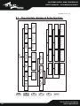
57 9.1 - Tree structure diagram of Setup function
58 10 - Practical guide
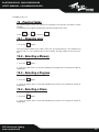
58 10.1 - Changing Page
58 10.2 - Selecting a Memory
58 10.3 - Selection a Program
58 10.4 - Selecting a Chase
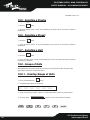
59 10.5 - Selecting a Psycho
59 10.6 - Selecting a Preset
59 10.7 - Selecting a Unit
59 10.8 - Groups of Units
59 10.8.1 - Creating groups of Units
60 10.8.2 - Eliminating a Unit from a Group
60 10.8.3 - Recalling a Group of Units
60 10.9 - Creating a Preset
61 10.10 - Creating a Psycho
62 10.11 - Creating a Chase
64 10.12 - Modifying Chase step times
65 10.13 - Re-patching a dimmer channel
66 10.14 - Patching the units
66 10.15 - Using a unit in manual
66 10.16 - Creating a Program
70 10.17 - Modifying program step times
Index

4
Pilot2000 version 1.32
Manual layout
All the parts of this user's manual have been laid out in such a way as to facilitate getting to know
the details of the Pilot 2000 lighting control board.
Each section is presented using the simplest possible terminology, although remaining necessa-
rily technical.
This new universal controller has been designed to ensure the utmost user-friendliness.
Chapters 1 and 2 are deliberately generic and conversational and have the job of presenting the
unit.
On the previous page, the index also gives an initial idea of how explanations of functions and
commands are divided, always beginning with the easiest and working up to the most complica-
ted.
We suggest even experienced operators read this manual in its entirety, as it's often possible to
appreciate every nuance in the logic of the unit's design only after completely understanding the
reasoning behind every choice made when designing both hardware and software.

5
www.sspworld.com
Pilot2000 version 1.32
1. Pilot 2000 layout
1.1 Main Features
Pilot 2000 universal lighting controller is one of the results of our long experience in the
manufacture of this type of control equipment, and is able to control 512 channels using DMX 512
protocol, of which a maximum of 192 channels can be set as dimmer channels and the rest reserved
for 40 intelligent units using up to a maximum of 36 channels each (the channel limit obviously
remains 512).
The quality and design are those the trade has come to expect from SSP and the sophisticated elec-
tronics used, combined with ground-breaking performance, places this unit at the top of the best inter-
national products. Careful in-depth study of the functions, an on-going search for innovative materials,
technical updating and constant research aimed at even greater safety have led to the realization of this
unique product.
This unit’s structure and electronics were entirely designed by our R&D lab, ensuring we have comple-
te command of the know-how and the best possible quality:price ratio.
Like all other SSP products, before being put on the market these boards underwent a lengthy burn-in
period, passing the strict tests with brilliant results: further proof of their high quality and reliability.
Great care taken with the lines and optimisation of the external structure to ensure utmost user-friend-
liness, enable them to be easily installed and facilitate any necessary maintenance work to the utmost.
The Pilot 2000 is built in compliance with current CE norms.
1.2 Technical Specifications
Power supply external AL (+12V DC, 2A max.) - cod. 003-1286
Power required +12VDC, 700mA
Power absorbed 8,4W
Electronics pFeatures CS 0238 + 0239 (main logic circuits); CS 0237 (control circuit)
CS 0234 + 0236 (cursors and joystick)
Storage protection a dipswitch allows programs and/or setup to be protected
Setting via dipswitches (for RS-232 and MIDI)
Inputs/Outputs - DMX IN/OUT via 5-pin XLR-F connector (*) for serial digital return signal;
- 6.3mm. stereo jack for up/down memory change pedal;
- 3mm. unbalanced stereo jack for audio IN - 0dB, mono (or left)
- DB9 connector for RS-232 serial connection with a personal computer;
- 3-pin XLR-F for SMPTE signal input;
- Standard 5-pin DIN connector for MIDI IN-THRU-OUT.
DMX channels: 512 (max.) configurable for intelligent units and dimmer channels
Unit frame Sheet metal with epoxy powder finish
Dimensions 5u rack 19” (cm 48,2 x 22,2 x 6,5 h max). Peso Kg 3,7
(*) wired for DMX return signal, not operative with this software version.

6
GB
appendix
IDFE
Pilot2000 version 1.32
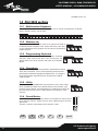
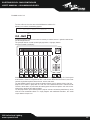
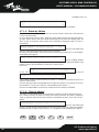
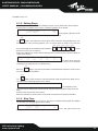
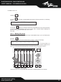
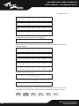
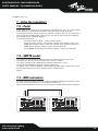
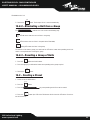
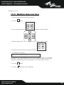
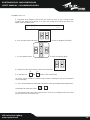
1.3 Pilot 2000 sections
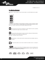
1.3.1 - Multifunction Keyboard
According to the function selected, this keyboard can be used to recall Memories, Programs,
Chases, Psychos, Presets, Units or Steps
1.3.2 - Memory obj
This section of buttons is used to select the 4 elements that make up
the Memory Objects (Program, Chase, Psycho and Preset). Once they'-
ve been programmed, these elements must be entered in the Memories
in order to be run.
1.3.3 - Programming Keyboard
This section comprises all the keys and the functions associated
with them, which allow to edit and set the running times and
general output levels of the elements that make up the Memory
Objects.
1.3.4 - Operations
This section is used to access Setup functions, dedicated to the control
of the desk's parameters (such as channel patching) and the libraries
containing the information regarding intelligent fixtures. It's also possi-
ble to record and play back stored events using the built-in SMPTE
signal generator.
1.3.5 - Utility
This section of the Pilot 2000 makes special functions such as Extra, Lamp e
Reset, immediately available: these operate directly on the luminaires (swit-
ching the lamp on and off), the intelligent fixtures (remote Reset) and the con-
trols sent to special units such as smoke machines or centrepieces (Extra
channels).
1.3.6 - Grand Master
Pilot 2000 has a general output level control, used to adjust the overall level of
all the "dimmer" channels, whether they are of the traditional type or of intelli-
gent fixtures.
The value is shown as a percentage, with a range of 0 - 100%.
1 2 3 4 5 6 7 8 9 10 11 12 13 14 15 16 17 18 19 20
multifunction keyboard
program chase psycho preset
memory obj
store edit levels times
programming keyboard
copy enter play
smpte
rec
operations
setup
extra lamp reset
utility
0
10
20
30
40
50
60
70
80
90
100%
grand master

7
www.sspworld.com
Pilot2000 version 1.32
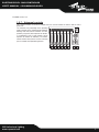
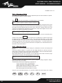
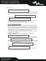
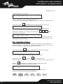
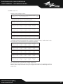
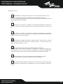
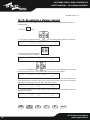
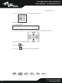
1.3.7 - Universal controls
This section includes the universal controls that are used to control the fixtures and the entire
Pilot itself.
The functions vary according to the operating
mode selected on the Programming Keyboard.
Moving head unit/scanner controls are com-
pleted by a joystick (which operates on absolu-
te co-ordinates) and 4 cursor buttons (which
operates on relative co-ordinates). The combi-
nation of these two systems ensures extremely
precise control when positioning fixtures.
pan tilt

8
GB
appendix
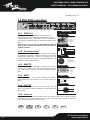
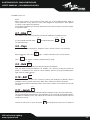
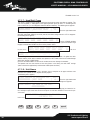
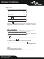
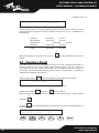
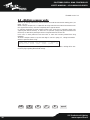
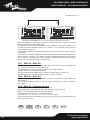
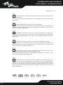
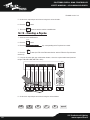
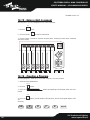
1.4 Pilot 2000 connectors
1.4.1 - DMX 512
The Pilot 2000 controller has DMX 512 input/output. At
the moment the input isn't enabled by the software. Certified
screened DMX512 cables (2x0.25mm) must be used for connec-
tions and must be of good quality to avoid faulty equipment ope-
ration.
Attention: the cable screen (braid) must NEVER be connected
to the system's ground, as this would cause faulty fixture or
controller operation.
1.4.2 - Pedal up-down
This connector allows a pedal to be connected to the controller
for stepping up and down through the memories. Pressing UP
and DOWN simultaneously switches the memory off. The
memory's enabled by pressing UP (starting from Memory 1) or
DOWN (starting from Memory 40).
1.4.3 - SMPTE
The SMPTE signal enables operators to record series of events
in sync with an SMPTE signal. This ensures absolutely precise
sync, ideal for use in musical, television and theatrical applica-
tions.
1.4.4 - MIDI
Pilot 2000 has Midi In, Thru and Out connectors. These offer a
considerable amount of functions. See the relative chapter for
details.
1.4.5 - RS-232
Using this connector, the desk can be connected to a PC. This
offers a considerable amount of functions. See the relative chap-
ter for details.
1.4.6 - Audio in
This socket allows to enable all the controller's music sync functions. When there's no direct connection
to an audio source, the built-in microphone is used. A LINE, mono, 0Db signal is required. An alternative
is to use the Left-hand channel of a stereo signal.
dmx pedal smpte midi settings audio in mainrs-232
1
2
3
4
5
in thru out in on/offinin
prg mem
1
midi rs-232
security lock
1
2
3
4
5
6
7
8
9
10
11
12
13
14
15
16
= on
in/outin/out
pin out:
1 = gnd
2 = -dmx out
3 = +dmx out
4 = -dmx in
5 = +dmx in
0dB mono signal
1
3
2
123456789
10
ON 54321
9876
socket wiring
1
2
3
4
5
dmx 512
1: gnd
2: -dmx out
3: +dmx out
4: -dmx in
5: +dmx in
pedal u/d
+V DC
gnd down up
1
3
2
smpte
1: gnd
2: signal hot
3: signal cold
rs-232
2: rx
3: tx
5: gnd
7: rts
8: cts
54321
9876
audio
gnd
left or mono
mains
gnd
n.c.
IDFE
Pilot2000 version 1.32

9
www.sspworld.com
Pilot2000 version 1.32
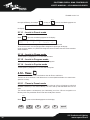
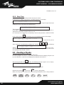
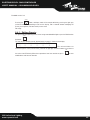
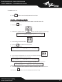
1.4.7 - Disconnecting the power supply
Pilot 2000 boards are powered by an AL4 switching power supply. This is fitted with a connector
plug and a small built-in locking mechanism that prevents accidental disconnection. To discon-
nect the power supply from the board, always grip the plug, not the cable, as shown in the dia-
gram:
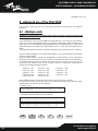
2 - Unit maintenance
2.1 Access to internal components
For access to the Pilot's internal components,
the 8 screws on the bottom of the frame must
be loosened.
There are no user-serviceable components
inside, so it's inadvisable to open the board:
only qualified technical personnel can carry
out work on the electronic components.
Before disconnecting the power supply, always remember to switch off the board.
2.2 Cleaning and periodical checks
The unit should be cleaned approximately every 100 hours, using compressed air to remove any
accumulated dust. The paint finish allows the board to be cleaned with alcohol or similar pro-
ducts: in any case, always use a non-abrasive cloth.
Make absolutely certain to avoid damaging the display by pressing too hard. To ensure perfect
unit efficiency, an overall check every 700 running hours is advisable. Electrical and mechanical
parts must be checked by qualified technical personnel.

10
GB
appendix
IDFE
Pilot2000 version 1.32
3 - Pilot 2000 controls
3.1 - Memory
Pilot 2000 is a universal controller able to control both intelligent lighting and dimmers.
Although manual control of the units can always be assumed at any point, the utmost can be
obtained from the board's performance by exploiting its Memories, powerful groups of controls
which work in a similar way to the “macros” used by computers.
Each Memory is used as a “container” able to hold (simultaneously):
- 4 Programs (intelligent fixture programs);
- 4 Chases (dimmer channel chases);
- 4 Psychos (assignment of dimmer channel switching to the 4 available audio bands:
Low, Mid-Low, Mid-High, High
- 4 Presets (lighting scenes created by the dimmer channels).
Pilot 2000 has 40 Memories, which over-ride each other.
3.1.1 - Mixing Techniques
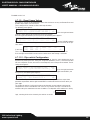
3.1.1.1 - HTP technique
Dimmer channels are switched on using HTP technique (Highest Takes Precedence): the highest
output level “passes”. This means that if 2 or more Presets are enabled on the same channel, the
channel level will be decided by the higher of the two, according to the following table, in which
the values should only be considered as examples:
Preset 1 channel 001 level 50%
Preset 2 channel 001 level 80%
Preset 3 channel 001 level 30%
Preset 4 channel 001 level 0%
Outputs channel 001 level 80%
HTP technique means that (in all cases) the output level never exceeds the highest and the level
doesn't correspond to the sum of the 4, which would give a level of 160%: the maximum output
level of a preset or a channel can never exceed 100%.
These is also the case for the Chases and Psychos and, obviously, for Chase/Psycho/Preset com-
binations.
Consequently, if channel 001 is used in the 3 elements, the output level of the channel will be the
highest of the 3. Again in this case, it's possible to represent this condition with a table (assu-
ming we observe the output at the instant x):
Preset 1 channel 001 level 50%
Chase 1 channel 001 level 40%
Psycho 1 chabbel 001 level 70%
Outputs channel 001 level 70%
So, in the condition shown here, only the Psycho will be visible, as its level is higher than that of
the Chase and Preset.
memory

11
www.sspworld.com
Pilot2000 version 1.32
3.1.1.2 - LTP technique
LTP (Latest Take Precedence) technique is normally used to control the intelligent lighting sec-
tion. In this way, the “moderator” of the signals in output (which will control moving head fixtu-
res, scanners and anything else) is time: when a unit is controlled by several Programs (and the-
refore by several Memories), only the most recent command will be sent to it. Here again, a table
is of assistance:
Unit 1 instant x operation: moving Pan to point 0.0 in 10 sec
Unit 1 instant x+1sec. operation: moving Pan to point 255.0 in 15 sec
Unit 1 instant x+3sec. operation: moving Pan to point 100.100 in 2 sec
Output instant x+3sec. operation: moving Pan to point 100.100 in 2 sec
In this example, if the initial movement requires 10 seconds, there will be a first change at instant
x + 1 second which will reach the new co-ordinates in a time of 15 seconds and a final change
at the instant x + 3 seconds which will reach the final co-ordinates in 2 seconds.
LTP technique means that the total time of the movement isn't the total of the 3 (27 seconds),
but is obtained by summing the last time with the time from the start of the sequence (therefore
approximately 6 seconds).
This mixing technique is used with Program and Memory.
3.2 - Program
Pilot 2000 has 40 programs, any 4 of which can run simultaneously.
The use of several simultaneous programs has the obvious limit that a certain controlled unit (e.g.
a scanner) cannot have one of its effects (e.g. the colour) used simultaneously by several pro-
grams: due to LTP mixing technique (see 3.1.1.2) only the last command received would be run,
not all of them simultaneously.
Simultaneous use of programs however allows operators to control light shows with the utmost
freedom, for example using program 1 for the colourchangers for a backdrop, 2 for the scanners
downstage, 3 for moving head fixtures and 4 for front of house colourchangers.
In permanent installations, this feature can be used (for example) to control the fixtures in diffe-
rent zones of the venue.
We're certain that all operators will be able to imagine convenient ways of using this
control facility.
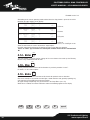
Each Program contains a maximum of 40 Steps (scenes). To select a Program, first select one of
the 40 Memories available. If a Memory isn't enabled, the following appears on the
display: .
3.3 - Chase
Pilot 2000 has 192 channels that can be reserved for control of the dimmer channels.
These 192 channels can be animated thanks to Chases, series of on/off commands that can be
programmed by the operator.
chase
--- YOU MUST SELECT A MEMORY ---
program

12
GB
appendix
IDFE
Pilot2000 version 1.32
40 Chases are available, each made up of a maximum of 40 Steps.
In each step, it's possible to set:
- the level at which each channel is switched on (from 0 to 100%)
- the length of the step (Time, from 0 to 999 tenths of a second)
- the time taken to pass from one step to the next (Cross, from 0 to 100% of Time).
- general level.
- general timing.
To select a Chase, first select one of the 40 Memories available. If a Memory isn't enabled, the fol-
lowing appears:
.
The possibility of setting the cross time
from step to step allows to have a chase with
clear-cut changes between steps or a "soft"
changeover, in which the ‘cross’ creates a
“micro mix" between steps.
If CROSS is set at 100%, this means that it
lasts the same amount of time as the TIME of
the steps run, cancelling fade-up time and
thus obtaining a clear-cut ingnition.
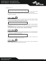
3.4 - Psycho
The 192 dimmer channels (see 3.3) can also be used to control fixtures in time with the music,
with the sync linked to 4 different audio bands.
Pilot 2000 has 40 Psycho set-ups, which can be programmed
by the operator. For each of these, it's possible to assign:
- the level of single channels for each audio band.
- the general level.
- input/output time.
To select a Psycho, first select one of the 40 Memories available. If a Memory isn't enabled, the
following appears:
.
3.5 - Preset
This function also uses the 192 dimmer channels available on the Pilot 2000, which in this case
are used to create fixed lighting scenes. There are 40 Presets available, programmable by the
operator. For each of these, it's possible to assign:
- the level of each single channel used
- the general level of the entire Preset (Level, from 0 to 100%)
- the fade-up/fade-down times of the entire Preset (Times, from 0 to 999 tenths of a second).
preset
--- YOU MUST SELECT A MEMORY ---
psycho
--- YOU MUST SELECT A MEMORY ---
level
seconds
time
cross
chase
step

13
www.sspworld.com
Pilot2000 version 1.32
To select a Preset, first select one of the 40 Memories available. If a
Memory isn't enabled, the following appears:
.
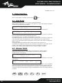
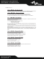
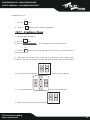
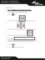
3.6 - Unit
Using this function, available even when no memory is enabled, access is gained to manual con-
trol of intelligent fixtures.
This group of controls is made up of 6 light grey faders, 6 light grey buttons,
movement controls and display:
.
Above each fader, the display indicates the effect it's controlling and the value set. Pressing one
of the buttons, control is assigned to the four cursor arrows. When Pan and Tilt are lit, the cursor
controls the positioning of the effects fixtures' mirrors and heads.
The two SCROLL buttons on the right of the display allow to scroll (in groups of 6 at a time) the
pages of unit's effects in group of 6 at a time. The units controlled can have a maximum of 36
channels, 30 for effects, 6 reserved for the moving parts and 2 for the options: each unit will the-
refore have a maximum of 5 pages of effects.
The 6th page contains preset moving effects (only for scanners and moving head fixtures), which
allow to create remarkable effects in a single program: with traditional controllers, this would
require dozens of steps cues.
pan tilt
DIMMR
0
COLOR
0
GOBOS
0
SHUTT
0
ROTGB
0
FROST
0
- 0
- 0
unit
--- YOU MUST SELECT A MEMORY ---

14
GB
appendix
IDFE
Pilot2000 version 1.32
3.6.1 - Groups of Units
Pilot 2000 is able to control 6 groups of Units independently of each other and offers the possibi-
lity of recalling the groups whenever required.
When is pressed and held down, the following appears on the display:
.
The 6 groups are assigned to the 6 light grey universal buttons and only one group can be used at
a time. To select the group of Units, press the button corresponding to the writing on the display,
then enable the Units required, which must all be of the same type. The green LEDs of the Units
selected on the Multifunction Keyboard and assigned to a Group flash together and the Units'
parameters are shown on the display, for example:
.
When the Units that make up a group have different parameter values, these are replaced by three
asterisks on the display . These asterisks will be replaced by a numerical value when
the effect of all the Units reaches the same value. In the event of mixed groups, i.e. those made
up of different types of intelligent fixtures, the only functions which can be controlled are those
regarding the movement of the mobile parts (mirror or moving head) - i.e. the Pan and Tilt chan-
nels. Any difference in the running of the movements will depend on the electromechanical cha-
racteristics of the relative fixtures.
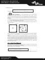
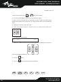
3.6.2 - Moving effects
Pilot 2000 has several pre-programmed moving cues, dedicated to scanners and moving head
fixtures.
Using these powerful controls, it's possible to create highly effective cues with just one com-
mand, and it's also possible to use them when creating programs, with the considerable advanta-
ge of preparing a complete moving light effect in just one scene.
After having selected a unit (e.g. a scanner), use the right-hand scroll button to reach the page
dedicated to these functions. The following appears on the display:
The effects available at the moment are Circle, Square, Diagonal 1 (Diag1), Diagonal 2 (Diag2),
Corner, Infinity (Inf.ty) and Zigzag.
The parameters which can be changed by the operator are:
X_SCL: scale on the X axis (from 0 to 100%)
Y_SCL: scale on the Y axis (from 0 to 100%)
SPEED: speed at which the effect runs (from 0 to 255)
RUN: direction of movement (normal or reverse)
ANG: starting angle of the effect (from 0° to 359°).
Using the scale and speed parameters, it's possible to deform the initial shape, thus creating
SHAPE X_SCL Y_SCL SPEED RUN ANG XXX
static --- --- --- ----- --- YYY
FUNC
***
IRIS COLOR GOBOS SHUTT - 0
0 0 0 0 -- -- - 0
select other units to make a group
GRP1 GRP2 GRP3 GRP4 GRP5 GRP6
unit

15
www.sspworld.com
Pilot2000 version 1.32
others.
When several scanners are used with the same effect, the use of the ANG parameter allows to
create spectacular “chase” effects: this value in fact staggers the various fixtures, which appears
as a delay in carrying out the movement.
Some moving light effects give the most spectacular results when the fixtures used have a regular
or symmetric layout.
3.7 - Step
This control is used to select the step to be created or modified in a Program or Chase.
It's only enabled when Edit mode ( )is enabled along with or .
The Edit LED flashes.
3.8 - Page
Pilot 2000 has 2 pages for Memories, Programs, Chases, Psychos, Presets, Units and Steps.
When the button's LED is off ( )page 1 is enabled (selections from 1 to 20), whereas
when ( ) is lit, page 2 is enabled (selections from 21 to 40).
3.9 - Hold
The Hold function allows to store the Elements created in the programs.
Hold also allows to copy the Memories. For example, if it's necessary to copy the contents of
Memory 1 to Memory 2, first select the "source" Memory and then, pressing and holding down
Hold, select the "target" memory.
3.10 - Edit
This control is used to access the section for creating and modifying the Memory Objects
(Programs, Chases, Psychos and Presets). When Edit is enabled, the relative LED flashes.
Each function has different operating modes, so the relative sections in this manual must be read
for details.
3.11 - Levels
Allows to set the general level of the Memory Objects (Programs, Chases, Psychos and Presets).
This function operates simultaneously (but individually) on all 4 elements of the Memory Objects
assignable to a Memory and is only enabled for the elements of the Memory Objects that have
already been selected.
To store the new levels set, press the button and, keeping it pressed, press the button of
hold
levels
edit
hold
page
page
chase
program
edit
step

16
GB
appendix
IDFE
Pilot2000 version 1.32
the required Memory (for example ). As long as is pressed, the following appears on
the display: .
3.11.1 - Levels in Preset mode
When , is pressed, the following appears on the display:
.
“PRE0x” indicates (in chronological order) which Preset has been selected.
To set the new values, use the light grey faders alongside the printing on the display.
Using the cursor buttons, it's possible to change the values and move from one Preset to another
of the 4 available.
3.11.2 - Levels in Chase mode
The description in paragraph 3.11.1 is also valid for Chases.
3.11.3 - Levels in Program mode
The description in paragraph 3.11.1 is also valid for Programs.
3.11.4 - Levels in Psycho mode
The description in paragraph 3.11.1 is also valid for Psychos.
3.12 - Times
This function allows to set fade-in and fade-out time for Presets and Chases.
The time can be set between 0 and 999 tenths of a second (600 hundredths of a second corre-
spond to 1 minute).
3.12.1 - Times in Preset mode
In this operating mode, Times allows to set the fade-up time of a Preset (a lighting cue with fixed
dimmable luminaires) in the relative Memory. The cue's fade-up and fade-down times are the
same.
This function operates simultaneously (but individually) on all the 4 Presets assignable to a
Memory, and is only enabled on Presets that have already been selected.
When , is pressed, the following appears on the display:
times
times
PRE04 PRE03 PRE02 PRE01
[255] 0 0 0 levels ok->
levels
--- SELECT DESTINATION MEMORY ---
hold
1

17
www.sspworld.com
Pilot2000 version 1.32
.
Once the times required have been set, when OK is pressed (right-hand scroll button on the right
of the display ): use Hold to store the changes.
3.12.2 - Times in Chase mode
When working in Chase mode, the Times function can be used to set the following for each of the
4 Chases:
- Trigger (TRIG) built-in or musical sync signal (INTRN or MUSIC)
- Direction (RUN) normal or reverse running (NORM or BACKW)
- Speed (SPEED%) running speed (from 25% to 400% of default speed).
When , is pressed, the following appears on the display:
. To select the Chases, use
the Multifunction Keyboard keys. The 4 Chases of the current Memory will be indicated by the
relative lit LED , the Chase whose Times are being set will have the relative LED flashing
.
The music sync uses the signal picked up by the built-in microphone or the Audio In connector.
When Pilot 2000 is connected to an audio signal, the built-in microphone is automatically by-pas-
sed.
Chases normally run from step 1 to step 40. When a run is set on BACKWard, it goes from Step
40 to Step 1.
When creating a Chase, operators can set the duration time of each single Step.
By means of the Speed control, it's possible to accelerate up to 400% or slow down to 25% the
overall chase running speed, which will otherwise run at a default speed of 100%. The variation is
relative to the times set, which will all be subject to the acceleration or deceleration required, but
will maintain the characteristic of different step times set when creating the Chase.
3.13 - Copy
Pilot 2000 has 40 Programs, 40 Chases, 40 Psychos and 40 Presets. The Copy function allows
operators to copy the elements making up the Memory Objects, obtaining new elements identical
to the original ones.
When Copy is enabled, the relative LED flashes.
copy
1
2
CHA TRIG RUN SPEED%
01 [INTRN] NORML 100 ok->
times
PRE04 PRE03 PRE02 PRE01
[600] 0 0 0 rise/fall ok->

18
GB
appendix
IDFE
Pilot2000 version 1.32
AAccording to the current operating mode enabled when the Copy button is pressed, one of the
following messages appears on the display:
if in Preset;
if in Chase;
if in Psycho;
if in Preset.
The Up/Down cursor arrows are used to select the elements available, the Left/Right cursor
arrows to move from the "source" object to the "target“ object.
Press OK (right-hand Scroll button) to confirm the copy, ESC to abort the operation.
There's no “Undo” type of function for restoring the condition before the one confirmed with
OK.
3.14 - Enter
The Enter button is used to confirm storage of the new elements that make up the Memory
Objects or any modification made to them.
3.15 - Play
The Play function allows to run one of the 20 tracks of previously recorded “events”.
For details, see the relative chapter.
3.16 - Extra
Pilot 2000 allows to reserve a maximum of 48 channels for particular units or functions.
One classic example is the control of strobe lights, smoke machines and, generally speaking, any
units requiring just one DMX channel for their control.
All signal settings and patching must be carried out in the Setup Menu (see 3.19).
When Extra is enabled, the relative LED flashes and on the following appears on the display:
extra
play
enter
COPY OBJECT FROM TO esc<-
PRE [01]-> 2 ok->
COPY OBJECT FROM TO esc<-
PSY [01]-> 2 ok->
COPY OBJECT FROM TO esc<-
CHA [01]-> 2 ok->
COPY OBJECT FROM TO esc<-
PRG [01]-> 2 ok->

19
www.sspworld.com
Pilot2000 version 1.32
. The right and left-hand
SCROLL buttons allow to scroll through the 8 pages dedicated to the 48 “Extra channels”.
According to the type of units controlled as “Extras”, they can be enabled using the faders and the
light grey universal buttons.
3.17 - Lamp
By means of this control, it's possible to send fixtures with this function the code for switching
their lamp on and off. When the Pilot is switched on, default status is that the lamp is lit. When
Lamp is pressed, the following message appears on the display:
.
By holding the keys of the Multifunction Keyboard down for a few seconds, it's possible to switch
the lamp on or off. When the green LED is lit, this shows that the lamp is lit, when the LED's off,
the lamp's off.
It must be remembered that switching the lamp on and off frequently, particularly with fixtures
fitted with discharge lamps, reduces the lamplife, sometimes considerably!
3.18 - Reset
By means of this control, a command for resetting the electronics can be sent to fixtures with
this function. This is a type of direct action which the operator carries out on the units controlled.
The following message appears on the display:
.
By pressing the keys of the Multifunction Keyboard, it's possible to send the command. The
green LED lights up for as long as the key is pressed.
3.19 - Menu
This function is used to access the Setup Menu, by means of which the units are patched and
libraries managed. See chapter 4 for details of this function.
menu
PUSH UNIT`S KEYS TO SEND RESET
reset
SWITCH LAMPS BY HOLDING DOWN KEYS
lamp
EXT01 EXT02 EXT03 EXT04 EXT05 EXT06 <->
[ 0] 0 0 0 0 0

20
GB
appendix
IDFE
Pilot2000 version 1.32
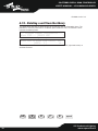
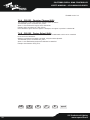
4 - Setup functions
Access is gained to these functions by pressing the button.
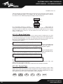
4.1 - Unit Patch
To control the 40 Units, it's necessary to carry out patching procedure.
When the Menu button flashes, the up/down cursor arrows are used to scroll through the options
available until the following screen appears:
.
Pressing the right-hand arrow of the SCROLL buttons gives access to the setting menu:
.
The cursor arrows can be used to assign the parameters (up and down to increase or decrease
the values, right and left to move from function to function).
In the above case, unit 1 is an, whose starting address is set at 100.
Pilot 2000 automatically calculates the last channel required by that unit and on the right-hand
side of the display shows the configuration to set on the dipswitch on the rear of the fixture.
In this case (as conventionally done), the dipswitch's "ON" position is that in which a small square
appears at the top.
Pressing the button corresponding to <DEL> deletes what has been previously set.
The operator isn't obliged to assign the units numerically rising patches (for example 100 for
number 1 and 125 for 2), but can handle the Units at his or her disposal as required.
Press one of the SCROLL buttons again to leave this function: storage is automatic.
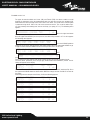
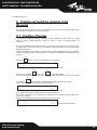
4.2 - Dimmer Patch
This function allows to set which DMX channels correspond to the “dimmer channels”.
When the Menu button flashes, use the up/down cursor arrows to scroll the options
available until this screen appears:
.
For access to these settings, just press the right-hand arrow of the SCROLL buttons (on the right
of the display):
.
“DMX-CH” indicates the “physical” dimmer channel of the DMX chain (from 1 to 512); CHANNEL
shows which dimmer channel of the Pilot will control the chosen channel or channels; LIM% indi-
cates any attenuation on that channel and EQUAL the equalization curve assigned to the channel.
Pressing the light grey button below the display, corresponding to <DEL>, the settings made will
be deleted.
DMX-CH CHANNEL LIM% EQUAL ok->
[001] <---- 1 100 7 <DEL>
CONFIGURATION & SETUP MENU
SELECT --> [DIMMER PATCH ] ok->
UNIT TYPE FROM -100 1--cod--10
[ 1] VICTORY 2 <DEL> TO -111 ˘˘˛˛˛˘˘˛˛
CONFIGURATION & SETUP MENU
SELECT --> [UNIT PATCH ] ok->
setup
La pagina si sta caricando...
La pagina si sta caricando...
La pagina si sta caricando...
La pagina si sta caricando...
La pagina si sta caricando...
La pagina si sta caricando...
La pagina si sta caricando...
La pagina si sta caricando...
La pagina si sta caricando...
La pagina si sta caricando...
La pagina si sta caricando...
La pagina si sta caricando...
La pagina si sta caricando...
La pagina si sta caricando...
La pagina si sta caricando...
La pagina si sta caricando...
La pagina si sta caricando...
La pagina si sta caricando...
La pagina si sta caricando...
La pagina si sta caricando...
La pagina si sta caricando...
La pagina si sta caricando...
La pagina si sta caricando...
La pagina si sta caricando...
La pagina si sta caricando...
La pagina si sta caricando...
La pagina si sta caricando...
La pagina si sta caricando...
La pagina si sta caricando...
La pagina si sta caricando...
La pagina si sta caricando...
La pagina si sta caricando...
La pagina si sta caricando...
La pagina si sta caricando...
La pagina si sta caricando...
La pagina si sta caricando...
La pagina si sta caricando...
La pagina si sta caricando...
La pagina si sta caricando...
La pagina si sta caricando...
La pagina si sta caricando...
La pagina si sta caricando...
La pagina si sta caricando...
La pagina si sta caricando...
La pagina si sta caricando...
La pagina si sta caricando...
La pagina si sta caricando...
La pagina si sta caricando...
La pagina si sta caricando...
La pagina si sta caricando...
La pagina si sta caricando...
La pagina si sta caricando...
-
 1
1
-
 2
2
-
 3
3
-
 4
4
-
 5
5
-
 6
6
-
 7
7
-
 8
8
-
 9
9
-
 10
10
-
 11
11
-
 12
12
-
 13
13
-
 14
14
-
 15
15
-
 16
16
-
 17
17
-
 18
18
-
 19
19
-
 20
20
-
 21
21
-
 22
22
-
 23
23
-
 24
24
-
 25
25
-
 26
26
-
 27
27
-
 28
28
-
 29
29
-
 30
30
-
 31
31
-
 32
32
-
 33
33
-
 34
34
-
 35
35
-
 36
36
-
 37
37
-
 38
38
-
 39
39
-
 40
40
-
 41
41
-
 42
42
-
 43
43
-
 44
44
-
 45
45
-
 46
46
-
 47
47
-
 48
48
-
 49
49
-
 50
50
-
 51
51
-
 52
52
-
 53
53
-
 54
54
-
 55
55
-
 56
56
-
 57
57
-
 58
58
-
 59
59
-
 60
60
-
 61
61
-
 62
62
-
 63
63
-
 64
64
-
 65
65
-
 66
66
-
 67
67
-
 68
68
-
 69
69
-
 70
70
-
 71
71
-
 72
72


in altre lingue
- English: SSP PILOT2000 User manual
Altri documenti
-
 LSC AXIOM Manuale utente
-
PROEL PLBR256MH2 - REV 07-2006 Manuale utente
-
Leviton PPICS-V12 Manuale utente
-
-
ProLights 7x15W moving LED wash Manuale utente
-
-
-
-
-
