
User Manual
PICCOLO
Document Release March 2009
Rev. A
(12/48 model shown)
Document Release March 2009
Revision A
WEB VERSION

Leviton Piccolo
Warranty
Leviton Manufacturing Co Inc. warrants this control console to be free of material and workmanship defects
for a period of two years after system acceptance or 26 months after shipment, whichever comes first. This
Warranty is limited to repair of replacement of defective equipment returned Freight Pre-Paid to Leviton
Lighting Management Systems Division at PO Box 2210, Tualatin, Oregon 97062, USA. User shall call 1-
800-959-6004 and request a return authorization number to mark on the outside of the returning carton, to
assure that the returned material will be properly received at Leviton. All equipment shipped back to
Leviton must be carefully and properly packed to avoid shipping damage. Replacements or repaired
equipment will be returned to sender freight prepaid, F.O.B. factory. Leviton is not responsible for removing
or replacing equipment on the job site, and will not honor charges for such work. Leviton will not be
responsible for any loss of use time or subsequent damages should any of the equipment fail during the
warranty period, but agrees only to repair or replace defective equipment returned to its plant in Tualatin,
Oregon. This Warranty is void on any product that has been improperly installed, overloaded, short
circuited, abused, or altered in any manner. Neither the seller nor Leviton shall be liable for any injury, loss
or damage, direct or consequential arising out of the use of or inability to use the equipment. This
Warranty does not cover lamps, ballasts, and other equipment which is supplied or warranted directly to
the user by their manufacturer. Leviton makes no warranty as to the Fitness for Purpose or other implied
Warranties.
Notice
Although the information contained within this user guide is believed to be accurate at the time of printing,
it is not guaranteed to be without fault and is subject to change without notice. Future software releases
may change the features or operation of this product. For current information contact:
Leviton Lighting Management Systems Division
20497 SW Teton, Tualatin, OR 97062
Mailing Address:
PO Box 2210
Tualatin, OR 97062
Customer Service: (800) 736-6682
Technical Support: (800) 959-6004
Fax: (503) 404-5601
Email: [email protected]
Internet: www.leviton.com
Copyright © 2009
Leviton Manufacturing Company Incorporated.
All Rights Reserved.
WEB VERSION

User Manual
Table of Contents
1. Introduction ..............................................................................................................................1
1.1. Features.........................................................................................................................................2
2. Specifications.............................................................................................................................3
2.1. Top Panel.......................................................................................................................................4
2.2. Rear Panel......................................................................................................................................4
2.2.1. DMX In / Out Connections.........................................................................................................4
2.2.2. MIDI In / Out Connections.........................................................................................................5
2.2.3. USB Connections ......................................................................................................................5
2.2.4. Ethernet Connection .................................................................................................................5
2.2.5. LT-Link Connection...................................................................................................................5
2.2.6. VGA Connection........................................................................................................................6
2.2.7. Power Supply and Switch ..........................................................................................................6
2.2.8. Work Light Connection..............................................................................................................6
3. About this Manual (Text Conventions).........................................................................................6
4. Installation and Start Up ............................................................................................................7
4.1. Warnings !......................................................................................................................................7
4.2. Power On .......................................................................................................................................7
4.3. Console Reset.................................................................................................................................7
5. Getting Help..............................................................................................................................8
5.1. Help by Functions............................................................................................................................8
5.2. Contacting Technical Support...........................................................................................................8
6. Base Display / Base Screen.........................................................................................................9
6.1. Base Display...................................................................................................................................9
6.1.1. Base Display Background Color..................................................................................................9
6.2. Base Screen.................................................................................................................................. 10
6.2.1. 48 and 96 Channel Models.......................................................................................................10
6.2.2. 144 and 192 Channel Models...................................................................................................10
6.2.3. Base Screen Background Color.................................................................................................10
7. Navigation...............................................................................................................................11
7.1. Data Tables.................................................................................................................................. 11
7.1.1. Using Data Tables...................................................................................................................11
7.1.2. Using Option Windows............................................................................................................12
7.2. Display / Screen Symbols and Colors...............................................................................................12
8. Operating Modes .....................................................................................................................13
8.1. Single Mode.................................................................................................................................. 13
8.2. Double Mode ................................................................................................................................13
8.3. Theatre Mode ...............................................................................................................................13
8.4. Manual Mode................................................................................................................................ 13
8.5. Selecting Operating Modes.............................................................................................................13
8.5.1. Mode Change and Channel Access ...........................................................................................14
9. Editing Channels......................................................................................................................15
9.1. Grand Master / Blackout Key..........................................................................................................15
9.2. Using Channel Faders....................................................................................................................15
9.3. Using the Keypad..........................................................................................................................15
9.3.1. Selecting Channels..................................................................................................................15
9.3.2. Editing Channel Levels ............................................................................................................16
Manual Rev. A i
WEB VERSION

Leviton Piccolo
9.3.3. De-Selecting (Releasing) Channels ...........................................................................................16
9.3.4. Other Editing Commands.........................................................................................................16
9.4. Channel Editing Examples..............................................................................................................17
9.4.1. Using Channel Faders..............................................................................................................17
9.4.2. Using the Keypad....................................................................................................................17
9.4.3. Channel Editing Example in Theatre and Manual Modes ............................................................. 17
9.4.4. Channel Editing Example in Single Mode...................................................................................17
9.4.5. Channel Editing Example in Double Mode..................................................................................17
10. Recording and Modifying Groups.............................................................................................18
10.1. Recording Groups........................................................................................................................ 18
10.2. Adding Attributes (Names, Times, etc.) to Groups ..........................................................................18
10.2.1. Using the Options Key...........................................................................................................18
10.2.2. Timing Modes (Tm)...............................................................................................................18
10.3. Modifying Groups ........................................................................................................................19
11. Recording and Modifying Cues................................................................................................20
11.1. Recording Cues...........................................................................................................................20
11.2. Adding Attributes (Names, Times, etc.) to Cues.............................................................................. 20
11.2.1. Using the Options Key...........................................................................................................21
11.2.2. Timing Modes (Tm)...............................................................................................................21
11.3. Modifying Cues............................................................................................................................21
12. Using Submasters (Theatre & Manual Modes)..........................................................................22
12.1. Loading Groups and Cues into Submasters ....................................................................................22
12.1.1. Cue Lists in Submasters.........................................................................................................23
12.2. Submaster Playback.....................................................................................................................23
12.2.1. Normal, Absolute or Inhibit Modes..........................................................................................23
12.3. Deleting Submasters....................................................................................................................24
12.4. Rate and Level Submasters ..........................................................................................................24
12.5. Effects Submasters......................................................................................................................24
12.5.1. Programming Effects.............................................................................................................24
12.5.2. Loading Effects.....................................................................................................................25
12.5.3. Executing Effects ..................................................................................................................25
12.5.4. Modifying Effects ..................................................................................................................25
13. Using the CrossFader (Theatre, Manual & Simple Modes) .........................................................26
13.1. Assigning Cues to the Crossfader..................................................................................................26
13.1.1. Jump and Loop (Lp) Functions...............................................................................................26
13.2. Crossfader Playback.....................................................................................................................27
13.2.1. Modify Fade Rate.................................................................................................................. 27
13.2.2. Modify Current Cue...............................................................................................................27
13.3. Deleting Cues from the Crossfader................................................................................................27
14. Using Pages (Theatre & Manual Modes) ..................................................................................28
14.1. Recording Pages..........................................................................................................................28
14.2. Loading Pages.............................................................................................................................28
14.2.1. Normal Mode........................................................................................................................28
14.2.2. Forced Mode......................................................................................................................... 28
14.3. Deleting Pages............................................................................................................................28
15. Using Fixtures........................................................................................................................29
15.1. Selecting Fixtures and Editing Parameters......................................................................................29
15.1.1. Other Fixture Commands.......................................................................................................29
ii
WEB VERSION

User Manual
16. Using Shapes.........................................................................................................................30
16.1. Shape Basics...............................................................................................................................30
16.1.1. Editing and Recording a New Shape .......................................................................................30
16.2. Other Shape Options....................................................................................................................31
16.2.1. Items Selection Order............................................................................................................31
16.2.2. Add Shape............................................................................................................................ 31
16.2.3. Using Shapes in Playbacks.....................................................................................................31
16.2.4. Examine Shapes List.............................................................................................................. 31
16.2.5. Examine Cues and Groups containing Shapes.......................................................................... 31
16.3. Shape Base Configuration............................................................................................................. 31
16.3.1. All Groups and Cues..............................................................................................................31
16.3.2. Individual Groups and Cues ...................................................................................................32
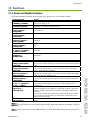
17. Functions...............................................................................................................................33
17.1. Exam and Modify Functions..........................................................................................................33
17.2. Test and Next Functions...............................................................................................................34
17.2.1. Test.....................................................................................................................................34
17.2.2. Next ....................................................................................................................................34
17.3. Copy and Exchange Functions ......................................................................................................34
17.4. Delete Functions..........................................................................................................................34
17.4.1. Deleting Submaster and Crossfader Contents ..........................................................................34
17.4.2. Deleting Cues and Groups......................................................................................................35
17.4.3. Deleting Effects, Pages and Macros ........................................................................................35
17.5. Learn Time Functions...................................................................................................................35
17.6. Macro Functions..........................................................................................................................36
17.6.1. Recording Macros .................................................................................................................36
17.6.2. Modifying Macros..................................................................................................................36
17.6.3. Deleting Macros....................................................................................................................36
17.6.4. Executing Macros..................................................................................................................36
18. Patching................................................................................................................................37
18.1. Patching Dimmers .......................................................................................................................37
18.1.1. Testing Dimmers................................................................................................................... 37
18.1.2. Pre-Programmed Curves........................................................................................................38
18.1.3. House Light Dimmers............................................................................................................38
18.1.4. Patch Tools ..........................................................................................................................39
18.2. Patching Fixtures.........................................................................................................................39
18.2.1. Scroller Definition..................................................................................................................40
18.3. Cache List Configuration............................................................................................................... 41
18.4. Fixture Definition.........................................................................................................................42
19. Saving and Loading Show Data...............................................................................................43
20. Console Updating...................................................................................................................43
21. Menus...................................................................................................................................44
21.1. Patches ...................................................................................................................................... 44
21.1.1. Dimmers (Menu 02) & Fixtures (Menu 04)...............................................................................44
21.1.2. Dmx In (Menu 03) ................................................................................................................44
21.2. Disk & Printer..............................................................................................................................44
21.2.1. Disk (Menu 10).....................................................................................................................44
21.2.2. Printer (Menu 11) .................................................................................................................44
21.3. Multimedia..................................................................................................................................44
21.3.1. Midi (Menu 21) & Time Code (Menu 23),.................................................................................44
21.3.2. External Triggers & Sound (Menu 22).....................................................................................44
21.4. Setup .........................................................................................................................................45
21.4.1. Editor & Times (Menu 30)......................................................................................................45
Manual Rev. A iii
WEB VERSION

Leviton Piccolo
21.4.2. Playbacks (Menu 31).............................................................................................................45
21.4.3. System (Menu 32).................................................................................................................46
21.4.4. Dmx Setup (Menu 33)...........................................................................................................46
21.4.5. Power-Up Macro (Menu 34)...................................................................................................46
21.4.6. Remote and PocketPC (Menu 35) ...........................................................................................47
21.4.7. Wireless DMX (Menu 36) .......................................................................................................47
21.5. Ethernet ..................................................................................................................................... 47
21.5.1. Ethernet Configuration (Menu 40) ..........................................................................................47
21.6. Special Commands ......................................................................................................................47
21.6.1. Multimedia Panel (Menu 70)................................................................................................... 47
21.6.2. Status & Playbacks Zero (Menu 71) ........................................................................................47
21.6.3. Delete Console Show (Menu 72).............................................................................................48
21.6.4. Security & Defaults (Menu 77) ...............................................................................................48
21.6.5. Tools & Software Updates (Menu 79)......................................................................................48
21.6.6. Tests (Menus 80 - 88)...........................................................................................................48
22. Using Ethernet.......................................................................................................................49
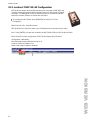
22.1. Ethernet Configuration.................................................................................................................49
22.2. Leviton LT NPC 2D/4D Configuration.............................................................................................50
23. Using MIDI, Time Code, External Triggers & Sound..................................................................51
23.1. MIDI ..........................................................................................................................................51
23.1.1. MIDI Configuration................................................................................................................ 51
23.2. Time Code (Events List)...............................................................................................................51
23.2.1. Events List Execution.............................................................................................................52
23.3. External Triggers & Sound Inputs ................................................................................................. 53
24. Off Line Editor (OLE)..............................................................................................................54
24.1. Introduction................................................................................................................................54
24.2. PC Requirements.........................................................................................................................54
24.3. Starting the OLE..........................................................................................................................54
24.4. Exchanging Data with a Console...................................................................................................54
24.5. Using the OLE as a Backup Console ..............................................................................................54
24.6. PC KeyBoard HotKeys ..................................................................................................................55
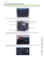
25. Installing Optional Video Card.................................................................................................56
iv
WEB VERSION

User Manual
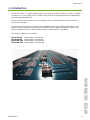
1. Introduction
The Leviton Piccolo is a compact lighting console with advanced functions normally not found on consoles
of similar size. It is very simple to use, yet offers many functions for complex procedures as demanded in
the lighting entertainment field.
Piccolo is an ideal control solution for use in theatres, schools, music and corporate venues, houses of
worship and TV studios.
The console can be operated in a variety of ways depending on the user’s needs and experience; it can
function as a basic two-scene manual console, submasters can be loaded with timed cues, groups, and
effects, or sequenced cues can be executed manually or automatically via a crossfader.
The console is offered in four 4 models:
Piccolo 12/48: 12 Submasters / 48 Channels
Piccolo 24/96: 24 Submasters / 96 Channels
Piccolo 36/144: 36 Submasters / 144 Channels
Piccolo 48/192: 48 Submasters / 192 Channels
Manual Rev. A 1
WEB VERSION

Leviton Piccolo
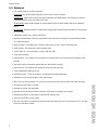
1.1. Features
x Four modes allow for versatile operation:
Single Mode
: All console faders operate as direct access control channels.
Double Mode
: Upper faders control the same channels as the lower faders, thus allowing for manual
crossfades between upper and lower fader rows.
Theatre Mode
: Upper faders operate as channel faders while the lower faders operate as submaster
faders.
Manual Mode
: Operates same as Theatre Mode except upper channel faders contribute to output levels
on a HTP basis.
x Submasters accept Cues, Groups and Effects.
x Channel and Submaster Flash keys. Submaster Flash keys can be configured in three different modes:
GO, FLASH and SOLO.
x Modify function: For modification of memory items such as Cues, Groups and Submasters.
x
placement in menus and data cells.
x itor: For creating cues and groups by entering levels via the alphanumeric keypad or level
ponse curves and limit functions.
rd-protected status.
console with other consoles and external devices.
onitor (VGA-output is available as an option).
x
x OLE (Off Line Editor): A complete console simulator that allows the user to edit shows on a PC. Can also
function as a backup console.
Exam function: For examining console memory items.
x 4 arrow keys for cursor
x 5 interactive softkeys.
Numeric ed
encoder.
x Any console item can be easily named with the alphanumeric keypad.
x Channel Patch: 512 dimmers with res
x 5 pre-programmed response curves.
x Installation Patch: To return console to a preset passwo
x Attributes to control moving lights, LED’s and scrollers.
x MIDI and Time Code functions: To synchronize the
x Personalized user setup of console.
x Operates in several user languages.
x Operates with or without an external m
x Storage and transfer of show data to external USB memory stick.
Printout of show data in text format.
2
WEB VERSION

User Manual
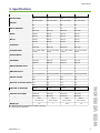
2. Specifications
Console Model: 12/48 24/96 36/144 48/192
Channel Faders 48 96 144 192
Total Channels (Dimmers and
Fixtures)
80 (512 Patch) (512 Patch) (512 Patch) (512 Patch) 128 176 224
Submasters 12 24 36 48
Fixture Attributes 32 32 32 32
Cues 999.9 (D) 999.9 (D) 999.9 (D) 999.9 (D)
Effects 999 (S) 999 (S) 999 (S) 999 (S)
Pages 999 (S) 999 (S) 999 (S) 999 (S)
Macros 999 (S) 999 (S) 999 (S) 999 (S)
Groups 999 (D) 999 (D) 999 (D) 999 (D)
Crossfaders 1 1 1 1
Crossfade Sequences 999.9 (D) 9.9 (D) 9.9 (D) 9.9 (D) 99 99 99
Crossfade Times T-In,
& Wait
T-Out, Delay T-Out, Delay T-Out, Delay T-Out, Delay T-In,
& Wait
T-In,
& Wait
T-In,
& Wait
Encoder Wheels 1 1 1 1
Multifunction Fader 1 1 1 1
LCD Display 240 x 64 240 x 64 240 x 64 240 x 64
VGA Monitor Output Optional Optional Optional Optional
DMX 512 Dimmer Patch 1 1 1 1
DMX Universes Out 1 1 1 1
DMX Universes In 1 1 1 1
Dimmer Curves 5 pre-programmed 5 pre-programmed 5 pre-programmed 5 pre-programmed
Ethernet 10/100 Yes Yes Yes Yes
RS485 (LT-Link) Yes Yes Yes Yes
USB Ports (1 Host & 1 Device) Yes Yes Yes Yes
Midi In/Out Yes Yes Yes Yes
3 Pin XLR for Worklight Yes (1) Yes (1) Yes (2) Yes (2)
Offline Editor Software (OLE) Yes Yes Yes Yes
External Power Supply 12V/1.5A 12V/1.5A 12V/1.5A 12V/1.5A
Housing Aluminu Aluminum Aluminu Aluminum m m
Size (mm) 490 x
400 x 50-100
720 x
400 x 50-100
950 x
400 x 50-100
1180 x
400 x 50-100
Weight (kg) 3.5 5 6.25 7.5
D = Dynamic Memory (depending on available memory)
S = Static Memory (absolute)
Manual Rev. A 3
WEB VERSION

Leviton Piccolo
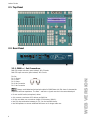
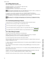
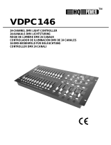
2.1. Top Panel
2.2. Rear Panel
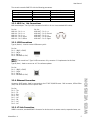
2.2.1. DMX In / Out Connections
DMX-512 output connector (opto-isolated): XLR-5 female.
DMX-512 input connector (opto-isolated): XLR-5 male.
Pin Out:
Pin 1: Ground.
Pin 2: Data –
Pin 3: Data +
Pin 4: No Connection
Pin 5: No Connection
Always use shielded and twisted pair cables for RS485 data with 120 ohms of characteristic
impedance and low capacitance. The Data – and Data + signals must be in the same twisted pair.
x Do not use XLR audio (microphone) cables.
x Only connect a maximum of 32 devices per DMX line.
x Do not use cables over a maximum length of 500 meters (1640 ft).
x Use 120 ohm termination between pin 2 & 3 on the last DMX device.
x Use DMX splitters to connect additional DMX users or for longer cable runs.
4
WEB VERSION

User Manual
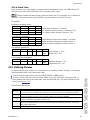
The console transmits DMX 512 with the following parameters:
Parameter Value DMX512 (1990) NORM
Break Length 90 Ps Minimum 88 Ps
MAB Length 48 Ps Minimum 8Ps
Bytes/packet 512 channels 1-512 channels
Break to break 25.000 Ps 170Ps – 3.000.000Ps
Updates/s 40 1-44
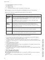
2.2.2. MIDI In / Out Connections
MIDI standard port: Two 5 pin DIN connectors for MIDI In & Out. Uses standard MIDI cables.
Pin Out: Pin Out:
MIDI-IN – Pin 1: n.c. MIDI-OUT – Pin 1: n.c.
MIDI-IN – Pin 2: n.c. MIDI-OUT – Pin 2: Ground
MIDI-IN – Pin 3: n.c. MIDI-OUT – Pin 3: n.c.
MIDI-IN – Pin 4: Signal MIDI-OUT – Pin 4: Return
MIDI-IN – Pin 5: Return MIDI-OUT – Pin 5: Signal
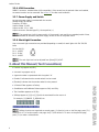
2.2.3. USB Connections
Type A (Device) - Used to connect USB memory stick:
Pin Out:
Pin 1 – VBUS (+5VDC)
Pin 2 – DATA -
Pin 3 – DATA +
Pin 4 – GROUND (0 VDC)
The console has 2 Type A USB connectors. Only connector 1 is implemented at this time.
Type B (Host) - Used to connect to a PC for software updates:
Pin Out:
Pin 1 – VBUS (+5VDC)
Pin 2 – DATA -
Pin 3 – DATA +
Pin 4 – GROUND (0 VDC)
2.2.4. Ethernet Connection
Connector: RJ45 female: Used for connection to the LT NPC 2D/4D Ethernet - DMX converter, Offline Editor
(OLE) and 3D visualizers such as Capture 2005.
Pin Out:
Pin 1 – TX+
Pin 2 – TX-
Pin 3 – RX+
Pin 4 – N.C.
Pin 5 – N.C.
Pin 6 – RX-
Pin 7 – N.C.
Pin 8 – N.C.
2.2.5. LT-Link Connection
SUBD-9 connector, standard RS485: Connector for devices such as remote controls, expansion boxes, etc.
Manual Rev. A 5
WEB VERSION

Leviton Piccolo
2.2.6. VGA Connection
SUBD-15 connector, standard video (VGA compatible). If the console has the optional video card installed,
an external monitor can be connected. See section 25
for video card installation.
2.2.7. Power Supply and Switch
An external power supply is provided with the console:
Voltage range: 90-264 VAC
Frequency: 47-63Hz
Output voltage: 12 VDC
Output current: 1.5 A / 18W
Output connector: Standard type P1J. Centre positive (+)
The console has a built-in power switch. If the console is not used for an extended period of time,
it is recommended to disconnect the power supply as well as turn off the power switch.
2.2.8. Work Light Connection
One or two work light connections are provided (depending on model) for work lights with 12V-15V/5W
bulbs.
Pin Out (XLR-3):
Pin 1: 0 VREF
Pin 2: 12 VDC
Pin 3: 0 VREF
The work light level can be adjusted from [Menu] [32]:LIGHT.
3. About this Manual (Text Conventions)
x Function keys appear as [KEY].
x A numeric key appears as [#].
x A general number is represented with the symbol “#”.
x Encoder3 indicates that the encoder wheel is to be turned.
x
ppear as GMÚ and SMÚ.
x ssociated function next to it.
[Encoder] indicates that the encoder wheel is to be pressed.
x A Channel Fader appears as FaderÚ.
x GrandMaster and SubMaster Faders a
x The Crossfader appears as X1/X2Ú
Softkeys appear as [1_B] to [5_B] with the a
For example, [1_B]MODE, [2_B]BLIND, etc:
Softkey functions are organized on several pages. If a function is not on the first page, press [F
to search for it. If a function opens a s
+]
ub page, the [F+] LED will be lit. To return to the previous page,
press [F+] or make a valid selection.
6
WEB VERSION

User Manual
4. Installation and Start Up
4.1. Warnings !
!
Do not expose the console to rain or moisture or damage may occur.
! There are no user serviceable parts inside. Do not attempt any repairs yourself, as doing so will void
the warranty. Please contact Leviton Technical Support if the console is not functioning properly.
! If the console has been stored in a cold environment (below 40ºF), do not turn the power on until it
warms up or else damage may occur.
! Avoid situations that could cause condensation to occur inside the console.
! Make sure that the mains power outlet matches the required voltage for your console.
! Do not operate the console if the power cord is frayed or broken.
! Do not remove the ground prong from the power cord. The ground prong is used to reduce the risk
of electrical shock and fire in case of an internal short.
! Do not operate the console if it becomes damaged in any way.
! Never operate the console with its cover removed.
4.2. Power On
If you observe any irregularity while unpacking the console (due to transportation damage, humidity, etc.)
do not attempt to switch on the console before contacting Leviton Technical Support.
1. Place the console on a flat surface.
2. Connect a proper DMX cable between the DMX-OUT port and the first DMX device (or splitter) in the
lighting system.
3. Connect an external monitor to the VGA connector (if video option ordered) using a standard video
cable.
4. Connect the external power supply to the DC-IN connector. Connect power supply plug to the mains
supply. If needed, the console can be connected to a UPS to avoid mains problems.
5. Switch on the console (rear switch in position I).
6. Set the GMÚ and SMÚ faders to 100%. Check that their respective blackout key LED‘s are off.
7. The console is now ready for operation. Please continue reading this manual.
4.3. Console Reset
The first time the console is started, and whenever necessary, a reset should be done:
1. Switch console off.
2. Press and hold down [I].
3. Switch console on.
4. After a few seconds, release [I].
A reset command will return the console to the following default situation:
x Channel fader levels will be set to 0%.
x Any stored show data (cue, group, etc.) will be erased.
x Preset default data
can be recovered (to enable this option, press
[Menu][77]. If this option is not set,
the console will return to the manufacturer defaults).
Manual Rev. A 7
WEB VERSION

Leviton Piccolo
5. Getting Help
5.1. Help by Functions
¾
Press [HELP], then press a console key you would like information on.
¾
For example, for information on cues, press [HELP][CUE].
¾
Press [HELP] again to close screen.
5.2. Contacting Technical Support
If you cannot find answers in this User Manual, please contact Technical Support and we will be glad to
answer your questions.
You can also call us during regular business hours at 1-800-959-6004. Please have the console model
number and serial number available when you call.
Contact Information:
Leviton Lighting Management Systems Division
20497 SW Teton, Tualatin, OR 97062
Mailing Address:
PO Box 2210
Tualatin, OR 97062
Customer Service: (800) 736-6682
Technical Support: (800) 959-6004
Fax: (503) 404-5601
Email: [email protected]
Internet: www.leviton.com
8
WEB VERSION

User Manual
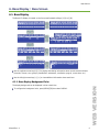
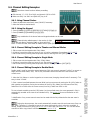
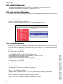
6. Base Display / Base Screen
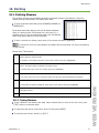
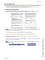
6.1. Base Display
The Base LCD Display is located on the front panel beneath softkeys [1_B] to [5_B]:
¾
Use the up/down arrow keys [K][L] for paging and viewing information about console status and items
(channels, fixtures, cues, groups, grandmaster, submasters, crossfaders, page #, current time, etc.)
¾
Use the left/right arrow keys [I][J] to view additional information about each item.
6.1.1. Base Display Background Color
The display background can be displayed in blue or dark blue.
¾
To configure the background color, press [MENU][32] then select DISPLAY.
Manual Rev. A 9
WEB VERSION

Leviton Piccolo
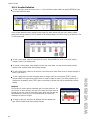
6.2. Base Screen
If the console model is equipped with the VGA option, console information can be viewed on a PC monitor.
¾
Use the up/down arrow keys [K][L] for paging and viewing information about console status and items
(channels, fixtures, cues, groups, grandmaster, submasters, crossfaders, page #, current time, etc.)
¾
Use the left/right arrow keys [I][J] to view additional information about each item. For example, to
view additional fixture parameters of patched fixtures.
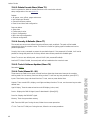
6.2.1. 48 and 96 Channel Models
All channels, fixtures (if patched), submasters, the events list (if On) and crossfader information is
shown. If multiple fixtures are patched, press the [K][L] keys to view fixture list.
6.2.2. 144 and 192 Channel Models
Due to the higher number of channels and submasters available with these models, it is necessary to page
information by pressing the [K][L] keys.
All channels, the events list (if On) and crossfader information is shown. Use the [K][L] keys to view
fixtures (if patched) and submasters information.
6.2.3. Base Screen Background Color
The screen background can be displayed in white, dark gray or black.
¾
To configure the background color, press [MENU][32] then select MONITOR.
10
WEB VERSION

User Manual
7. Navigation
¾
To exit data tables and menus, press [EXIT].
¾
To clear items in the command line, press [C].
¾
To close options windows, make a selection or press [C].
7.1. Data Tables
Areas where data can be viewed and edited are known as “Data Tables”, for example:
¾
To view the channel patch table, press [CHANNEL][CHANNEL].
¾
To view the cue list table, press [CUE][CUE].
¾
To exit a data table, press [EXIT].
7.1.1. Using Data Tables
Arrow Keys Each horizontal line contains data for one item (e.g. cue 1).
Press the [Ç][È] keys to move the item selection cursor (yellow line in base
screen).
Press the [Æ][Å] keys to move the editing cursor (red cell in base screen).
In the OLE software, the mouse can be used to select any cell on screen.
Item Search (Index #) Item number cells are located on the left side of the display or screen.
Use the [Ç][È] keys to search for a table item. Or, enter the item number then
press [ENTER] to jump to the item.
Edit Cell Each cell value or text can be edited using the alphanumeric keypad.
Select the desired cell (red in base screen) with the cursor then enter relevant data.
Press [ENTER] or any arrow key to accept data.
Cell Option Window When selected, some cells have an option window (see below) for selection of cell
options. Enter the index number of the desired option, or use the encoder wheel to
select the option then press the wheel to activate the option:
[DELETE] Key Used to delete data of a selected cell. After the data is erased, some cells will be
empty while other cells will show the default data value (depending on type of cell).
[INSERT] Key Works in different modes depending on the type of cell: Normally, it is used to edit
the order, or copy / increment data of the selected item from the previous selected
item. Useful in the fixtures patch and when editing effect steps, etc.
[OPTIONS] Key Used to toggle between the table’s options. Also used to quickly select a single
item’s options, for example [CUE][1][OPTIONS].
[EXIT] Key Closes the active table or menu. Remember to press [ENTER] to accept the last cell
data that was edited before closing the table.
Manual Rev. A 11
WEB VERSION

Leviton Piccolo
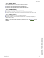
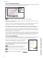
7.1.2. Using Option Windows
The console provides option lists or windows that are used for selectable commands. For example, pressing
[LOAD] will open the following window in which group load options can be selected:
To close options windows, make desired selection or press [C].
Numeric Selection Select the desired option by entering the index number, for example,
[#][ENTER].
In certain cases, pressing [ENTER] is not necessary (the window will close
automatically when digit is entered).
Selection by Mouse (OLE) In the OLE software, desired options can be selected with a mouse.
Selection by Encoder Wheel Move the encoder wheel to select the desired option then press [Encoder] or
[ENTER] to accept.
Selection by original
function key ([LOAD] &
[2_B]SHAPE)
Only for [LOAD] and [2_B]SHAPE option windows: Press the key again to
select the next option.
Options preceded by the “?” symbol in the LCD display are not available for selection (greyed out
in base monitor).
For [LOAD] or [2_B]SHAPE windows: Options in yellow characters (in base monitor) are selected.
Use the encoder wheel (green cursor in base monitor) to pre-select other options.
For the [5_B]PARAM window: Options in yellow characters (in base monitor) are special
commands for fixture ignition and control. Use the encoder wheel (green cursor in base monitor) to pre-
select other options.
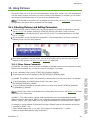
7.2. Display / Screen Symbols and Colors
Source View in Base Monitor View in Base Display
Editing Channels Red (Light Red for active channels)
Eŀ (EŶ for active channels)
Editing Channels in
Manual Mode
Magenta Ma
Submasters Yellow Sm
Inhibited Submasters Black Level over inverted background.
X1 (Crossfader) Cyan X1
X2 (Crossfader) Light Cyan X2
12
WEB VERSION

User Manual
8. Operating Modes
The console offers four operating modes: Single, Double, Theatre and Manual.
8.1. Single Mode
All faders (C#Ú & S#Ú) operate as individual channel faders. This mode is ideal for cue creation and
working with static scenes. Single mode is useful for editing because all channels are accessible using all
faders. In single mode, the crossfader is active but the submasters are not.
8.2. Double Mode
The upper and lower rows of console faders (C#Ú & S#Ú) operate as identical channel faders. With
Double Mode, the console has two scenes and is ideal for improvised manual sequences. The crossfader
controls the scene change between upper and lower fader rows. Not all functions of the crossfader and
submasters are accessible in this mode.
8.3. Theatre Mode
The upper faders, C#Ú operate as channel faders while the lower faders, S#Ú, operate as submaster
faders. This mode is a conventional working mode for lighting consoles, where all features are available.
8.4. Manual Mode
Operates same as Theatre Mode except channel faders contribute to output levels on a HTP basis. Channel
editing is only accessible via the keypad.
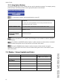
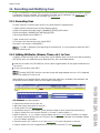
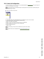
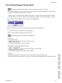
8.5. Selecting Operating Modes
1. Press [1_B]MODE.
The [1_B]MODE option is located in the
first page of the softkeys. If necessary, press [F+]
to search for it.
2. Select the desired mode:
¾
For Theatre mode, press [1_B]THEATRE. [CH.MD] LED will be off.
¾
For Single mode, press [2_B]SINGLE. [CH.MD] LED will be on.
¾
For Double mode, press [3_B]DOUBLE. [CH.MD] LED will be blinking.
¾
For Manual mode, press [4_B]MANUAL. [CH.MD] LED will be off.
The operating mode can be changed at any time. No data loss will occur with a mode change,
only access to various functions will be changed.
Manual Rev. A 13
WEB VERSION

Leviton Piccolo
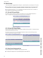
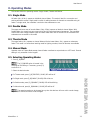
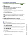
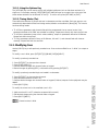
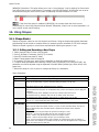
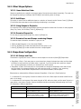
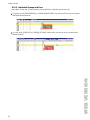
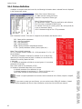
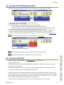
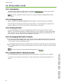
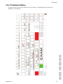
8.5.1. Mode Change and Channel Access
Model SINGLE Mode:
2 Banks
DOUBLE Mode:
4 Banks
THEATRE/MANUAL Mode:
4 Banks
Piccolo 12/48 [1-24] & [25-48] [1-12], [13-24], [25-36] & [37-48]
Piccolo 24/96 [1-48] & [49-96] [1-24], [25-48], [49-72] & [73-96]
Piccolo 36/144 [1-72] & [73-144] [1-36], [37-72], [73-108] & [109-144]
Piccolo 48/192 [1-96] & [97-192] [1-48], [49-96], [97-144] & [145-192]
¾
Press the [CH.MD] key to change channel banks. The active bank is marked with an LED (in example
below, the first bank is selected):
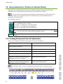
x Channel control in SINGLE mode. C (channel) LED’s (in middle of fader groups) are lit in green:
x Channel control in DOUBLE mode. C (channel) LED’s (in middle of fader groups) are lit in green:
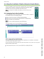
x Channel control in THEATRE/MANUAL mode. C (channel) LED’s (in middle of the upper faders) are lit in
green. S (submaster) LED’s are lit in red:
14
WEB VERSION
La pagina sta caricando ...
La pagina sta caricando ...
La pagina sta caricando ...
La pagina sta caricando ...
La pagina sta caricando ...
La pagina sta caricando ...
La pagina sta caricando ...
La pagina sta caricando ...
La pagina sta caricando ...
La pagina sta caricando ...
La pagina sta caricando ...
La pagina sta caricando ...
La pagina sta caricando ...
La pagina sta caricando ...
La pagina sta caricando ...
La pagina sta caricando ...
La pagina sta caricando ...
La pagina sta caricando ...
La pagina sta caricando ...
La pagina sta caricando ...
La pagina sta caricando ...
La pagina sta caricando ...
La pagina sta caricando ...
La pagina sta caricando ...
La pagina sta caricando ...
La pagina sta caricando ...
La pagina sta caricando ...
La pagina sta caricando ...
La pagina sta caricando ...
La pagina sta caricando ...
La pagina sta caricando ...
La pagina sta caricando ...
La pagina sta caricando ...
La pagina sta caricando ...
La pagina sta caricando ...
La pagina sta caricando ...
La pagina sta caricando ...
La pagina sta caricando ...
La pagina sta caricando ...
La pagina sta caricando ...
La pagina sta caricando ...
La pagina sta caricando ...
La pagina sta caricando ...
La pagina sta caricando ...
-
 1
1
-
 2
2
-
 3
3
-
 4
4
-
 5
5
-
 6
6
-
 7
7
-
 8
8
-
 9
9
-
 10
10
-
 11
11
-
 12
12
-
 13
13
-
 14
14
-
 15
15
-
 16
16
-
 17
17
-
 18
18
-
 19
19
-
 20
20
-
 21
21
-
 22
22
-
 23
23
-
 24
24
-
 25
25
-
 26
26
-
 27
27
-
 28
28
-
 29
29
-
 30
30
-
 31
31
-
 32
32
-
 33
33
-
 34
34
-
 35
35
-
 36
36
-
 37
37
-
 38
38
-
 39
39
-
 40
40
-
 41
41
-
 42
42
-
 43
43
-
 44
44
-
 45
45
-
 46
46
-
 47
47
-
 48
48
-
 49
49
-
 50
50
-
 51
51
-
 52
52
-
 53
53
-
 54
54
-
 55
55
-
 56
56
-
 57
57
-
 58
58
-
 59
59
-
 60
60
-
 61
61
-
 62
62
-
 63
63
-
 64
64


Leviton PPIC0-V24 Manuale utente
- Tipo
- Manuale utente
- Questo manuale è adatto anche per
in altre lingue
- English: Leviton PPIC0-V24 User manual
Documenti correlati
Altri documenti
-
Disc Makers PP-100 Setup Manual
-
 HQ Power 24-channel DMX light control panel Manuale utente
-
 HQ Power 24-channel DMX light control panel Istruzioni per l'uso
-
Numark AVM01 Manuale utente
-
 SSP PILOT2000 Manuale utente
-
Martin The Wife Manuale utente
-
Biamp 21 Series Mixing Console Operation Manuale utente
-
Yamaha PM4000 Manuale utente
-
-
PROEL PLBR256MH2 - REV 07-2006 Manuale utente


