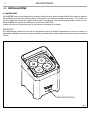
ProLights Wireless battery operated portable uplighter Manuale utente
- Categoria
- Stroboscopi
- Tipo
- Manuale utente
Questo manuale è adatto anche per

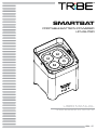
USER MANUAL
MANUALE UTENTE
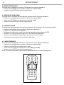
SMARTBAT
EN - IT
PORTABLE BATTERY-POWERED
UPLIGHTER

All rights reserved by Music & Lights S.r.l. No part of this instruction manual may be
reproduced in any form or by any means for any commercial use.
In order to improve the quality of products, Music&Lights S.r.l. reserves the right to modify the
characteristics stated in this instruction manual at any time and without prior notice.
All revisions and updates are available in the ‘manuals’ section on site www.musiclights.it
REV. 06-02/17

1
SMARTBAT
Packing content
• SMARTBAT
• Power cable
• IR Remote controller
• User manual
TABLE OF CONTENTS
Safety
General instructions
Warnings and installation precautions
1 Introduction
1. 1 Description
1. 2 Technical specications
1. 3 Operating elements and connections
2 Installation
2. 1 Mounting
3 Functions and settings
3. 1 Operation
3. 2 Basic setup
3. 3 Richarge
3. 4 Menu structure
3. 5 Auto Show
3. 6 Show speed
3. 7 Static color
3. 8 Sound mode
3. 9 Microphone sensitivity
3. 10 Manual color
3. 11 IR setup
3. 12 Master/Slave mode with DMX signal cable
3. 13 Master/Slave with wireless signal
3. 14 Operation with app SmartColors
3. 15 Operation with WIFIBOX
3. 16 Dimmer mode
3. 17 Linking
3. 18 DMX mode
3. 19 DMX addressing
3. 20 Connection of the DMX line
3. 21 Construction of the DMX termination
3. 22 DMX control
4 Maintenance
4. 1 Maintenance and cleaning the unit
4. 2 Fuse replacement
2
2
3
3
5
6
7
7
7
8
9
9
9
10
10
10
10
11
11
12
13
13
14
14
14
15
15
16
17
17

SMARTBAT
2
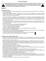
WARNING! Before carrying out any operations with the unit, carefully read this instruction
manual and keep it with cure for future reference. It contains important information about
the installation, usage and maintenance of the unit.
SAFETY
General instruction
• The products referred to in this manual conform to the European Community Directives and are there-
fore marked with
.
• Supply voltage of this product is DC24V; never connect directly to AC22V. Leave servicing to skilled
personnel only. Never make any modications on the unit not described in this instruction manual,
otherwise you will risk an electric shock.
• Connection of the power adapter must be made to a power supply system tted with ecient earth-
ing (Class I appliance according to standard EN 6598-1). It is, moreover, recommended to protect the
supply lines of the units from indirect contact and/or shorting to earth by using appropriately sized
residual current devices.
• The connection to the main network of electric distribution must be carried out by a qualied electri-
cal installer. Check that the voltage correspond to those for which the unit is designed as given on the
electrical data label.
• This unit is not for home use, only professional applications.
• Never use the xture under the following conditions:
- in places subject to vibrations or bumps;
- in places subject to excessive humidity.
• Make certain that no inammable liquids, water or metal objects enter the xture.
• Do not dismantle or modify the xture.
• All work must always be carried out by qualied technical personnel. Contact the nearest sales point for
an inspection or contact the manufacturer directly.
• If the unit is to be put out of operation denitively, take it to a local recycling
plant for a disposal which is not harmful to the environment.
Warnings and installation precautions
• If this device will be operated in any way dierent to the one described in this manual, it may suer
damage and the guarantee becomes void. Furthermore, any other operation may lead to dangers like
short circuit, burns, electric shock, etc.
• Before starting any maintenance work or cleaning the projector, cut o power from the main supply.
• Always additionally secure the projector with the safety rope. When carrying out any work, always com-
ply scrupulously with all the regulations (particularly regarding safety) currently in force in the country
in which the xture’s being used.
• Install the xture in a well ventilated place.
• Keep any inammable material at a safe distance from the xture.
• Shields, lenses or ultraviolet screens shall be changed if they have become damaged to such an extent
that their eectiveness is impaired.
• The lamp (LED) shall be changed if it has become damaged or thermally deformed.
• Never look directly at the light beam. Please note that fast changes in lighting, e. g. ashing light, may
trigger epileptic seizures in photosensitive persons or persons with epilepsy.
• This product is not intended for permanent installation.
• Do not touch the product’s housing when operating because it may be very hot.
• This product was designed and built strictly for the use indicated in this documentation. Any other use,
not expressly indicated here, could compromise the good condition/operation of the product and/or
be a source of danger.
• We decline any liability deriving from improper use of the product.

3
SMARTBAT
- 1 - INTRODUCTION
1.1 DESCRIPTION
SMARTBAT is a wireless light designed to rewrite the rules for battery operated xtures. Ensuring that high
performance and good design all housed in a compact size and price that makes it aordable makes the
SMARTBAT ideal for every kind of event. It can be remotely controlled through proprietary wireless DMX
protocol, the SmartColors app or through the IR controller - making it suitable for every level of user.
1.2 TECHNICAL SPECIFICATIONS
LIGHT SOURCE
• Source: 4x8W RGBW LEDs
• Luminous ux: 1127lm
• Lux: 833lux @3m full
• Source life expectancy: >50.000 h
OPTICS
• Beam angle: 13°
• Field angle: 30°
• Lens diameter: 42mm
• Additional optics: 25° and 45° optional
COLOUR SYSTEM
• Colour mixing: RGBW/FC
• White presets: 3200~10000K
• Colour wheel: virtual colour wheel with presets
DYNAMIC EFFECTS
• Static colour mode: selection of static colour
• Manual colour mode: manual adjustment of colour
• Auto mode: built-in programs with execution speed adjustment
BODY
• Tilt angle: adjustable foot support for tilt regulation (up to 20°)
• Body: sturdy die-cast aluminium body conceived for long-time durability
• Body colour: black, white nishing available
CONTROL
• Protocols: DMX512
• DMX channels: 4/6/10channel
• W-DMX: integrated, proprietary protocol compatible with WIFIBOX, WDBOX
• Display: LED display user interface
• Firmware upgrade: yes, via USB-DMX interface (UPBOX1) not included
• IR: infrared sensor controlled by remote
• Master/Slave: for synchronized operation of more units linked in a chain
ELECTRONICS
• Dimmer: linear 0~100% electronic dimmer
• Dimmer curves: 4 dierent dimming curves available

SMARTBAT
4
• Strobe / shutter: 1-25 Hz, electronic
• Operating temperature: 0° ~ +35°
• Flicker: icker free operation
ELECTRICAL
• Power supply: 100-240V – 50/60Hz
• Power consumption (at 230V): 30W
• Power consumption (at 120V): 31W
BATTERY
• Battery: 24V lithium
• Estimated battery life in colour change mode up to: 12h
• Estimated battery life in full-mode up to: 8h
• Re-charge connection: power cable
• Re-charge time: 5h/max
• Battery status: LED battery status indicator
PHYSICAL
• Cooling: natural cooling of the peculiar chassis and to absence of fans
• Sospension and xing: M12 threaded insert for easy clamp installation
• Signal connection: XLR 3p IN/OUT connectors
• Power connection: IEC IN/OUT connectors
• IP rating: 33
• Dimensions (WxHxD): 138x186x145mm
• Weight: 3.4kg
Fig.1
137,8 184
145
Illuminance at a Distance
15°
1.0m
0m
3.0m
5.0m
7.0m
0.23m
0.68m
1.14m
1.60m
Lux Center Beam Angle: 15° Beam Width
7498lx
833lx
299.9lx
153lx
Fig.2
Photometric data

5
SMARTBAT
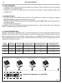
1.3 OPERATING ELEMENTS AND CONNECTIONS
Fig.4
Fig.3
Bottom panel
Side panel
2
MENU UP DOWN ENTER
4
4
1
3
6
9
8
7
5
1. MICROPHONE to control the show by the
external audio signal.
2. CONTROL PANEL with display and 4 button
used to access the control panel functions
and manage them.
3. CHARGE BATTERY LED.
4. Adjustable foot support for tilt regulation (up
to 20°).
5. ON/OFF SWITCH.
6. DMX IN (3-pole XLR):
1 = ground, 2 = DMX -, 3 = DMX +.
7. POWER IN mains plug for connection to a
socket (100-240V 50/60Hz) via the supplied
mains cable. The support for the mains fuse
is located near the mains plug. Only replace a
blown fuse by one of the same type.
8. DMX OUT (3-pole XLR):
1= ground, 2 = DMX -, 3 = DMX +.
9. POWER OUT: connect to supply power to the
next unit.

SMARTBAT
6
- 2 - INSTALLATION
2.1 MOUNTING
SMARTBAT may be set up on a solid and even surface. The unit can also be mounted upside down to a
cross arm. For xing, stable mounting clips are required. The mounting place must be of sucient stability
and be able to support a weight of 10 times of the unit’s weight.
When carrying out any installation, always comply scrupulously with all the regulations (particularly re-
garding safety) currently in force in the country in which the xture’s being used.
IMPORTANT
Always additionally secure the projector with the safety rope from falling down. For this purpose, fasten
the safety rope at a suitable position so that the maximum fall of the projector will be 20 cm.
Fig.5
THREADED HOLES M12

7
SMARTBAT
- 3 - FUNCTIONS AND SETTINGS
3.1 OPERATION
Switch on the SMARTBAT with the power switch. The unit is ready for operation and can be operated via a
DMX controller or it independently performs its show program in succession.
After operation, switch o the unit with the power switch.
3.2 BASIC SETUP
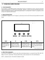
The SMARTBAT has a LED display and 4 buttons for access to the functions of the control panel (g. 6).
MENU UP DOWN ENTER
Used to access the menu or
to return a previous menu
option
Button to select the values
in ascending order of the
function
Button to select the values
in descending order of the
function
Used to select and store the
current menu or conrm the
current function value or
option within a menu
Fig.6 - Functions of the buttons
3.3 RICHARGE
To recharge SMARTBAT, plug the power cable into a mains socket (100-240V ~ / 50-60Hz).
NOTE - The charging time are 5 h and autonomy is 8h
MENU UP DOWN ENTER

SMARTBAT
8
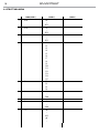
3.4 MENU STRUCTURE
MENU (LEVEL 1) (LEVEL 2) (LEVEL 3)
1 4 CH d1
~
d512
2 6 CH d1
~
d512
3 10 CH d1
~
d512
4 C-- C1
C2
C3
C4
C5
C6
C7
C8
C9
C10
C11
C12
C13
C14
C15
5 P-- P1
P2
P3
P4
6 S-- S1
~
S100
7 Snd
8 Sens u0
~
u100
9 U-- r0
~
r255
g0
~

9
SMARTBAT
3.5 AUTO SHOW
This xture has a built-in automatic program. To access this, please see the below instructions:
• Press the button MENU so many times until shows [P--].
• Press the button ENTER to conrm.
• Using UP/DOWN button, select one of the programs [P1 - P4].
• Press the button ENTER save the setting.
3.6 SHOW SPEED
To set the show speed refer to the following steps:
• Press the button MENU so many times until shows [S--].
• Using UP/DOWN button, select one of the programs [S1 - S100].
• Press the button ENTER save the setting.
3.7 STATIC COLOR
This xture has the ability to accept custom static color settings. Access these chases via the control panel
on the back of the xture.
• Press the button MENU so many times until shows [C--].
• Press the button ENTER to conrm.
• Using UP/DOWN button, select one of the programs [C1 - C15].
• Press the button ENTER save the setting.
g255
b0
~
b255
wo
~
w255
10 dIM OFF
dim1
dIM2
dIM3
11 SET ON
OFF
12 S-tr drAS drAU
drCH dr 1
~
dr16
dtAS dtAU
dtCH dt 1
~
dt16

SMARTBAT
10
3.8 SOUND MODE
To set the sound mode refer to the following steps:
• Press the MENU button so many times until the display shows [Snd].
• Press the ENTER button for save the setting.
3.9 MICROPHONE SENSITIVITY
To set the microphone sensitivity refer to the following steps:
• Press the button MENU so many times until shows [Sens].
• Using UP/DOWN button, select one of the programs [u1 - u100].
• Press the button ENTER save the setting.
3.10 MANUAL COLOR
This mode allows to combine the colors red, green, blue and white (r, g, b).
• Press the button MENU so many times until the display shows [U--], then press the button ENTER.
• Select the color (r, g, b) through the buttons UP/DOWN.
• Press the button ENTER to conrm.
• Using UP/DOWN button, select the desired color value [000 - 255].
• Press ENTER button to continue to the next color.
• Continue until the desired mix is obtained.
• Press the MENU button to go back or to meet the waiting time to exit the setup menu.
3.11 IR SETUP
To start up the IR recevitor refer to the following steps:
• Press the MENU button so many times until the display shows [Set].
• Press the ENTER button to conrm.
• Press the UP/DOWN button, select one of the programs [ON] or [OFF].
• Press the ENTER button for save the setting.
NOTE - Make sure to point the controller directly at the receiver on the product.
Fig.7
IRC REMOTE
BLACK
OUT
AUTO
STROBE SPEED
SOUND
SENSI-
TIVITY
%
MANUAL
FADE
SNAP
R
G B
+
0
1
2
3
4
5
6
7 8 9
A
UV W

11
SMARTBAT
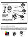
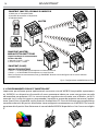
3.12 MASTER/SLAVE MODE WITH DMX SIGNAL CABLE
This mode will allow you to link up the units together without a controller. Choose a unit to function as the
Master. The unit must be the rst unit in line; other units will work as slave.
• Use standard DMX cables to daisy chain your units together via the DMX connector on the rear of the
units. For longer cable runs we suggest a terminator at the last xture (see page 16).
• Use any one of the standalone modes for the master unit.
• Set the slaves to the same DMX modes.
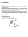
3.13 MASTER/SLAVE MODE WITH WIRELESS SIGNAL
This mode allows you to wirelessly connect more units SMARTBAT, without a controller. The rst unit,
transmitter signal, it will be set as master and the others, receivers, as slave.
Wireless communication between devices can be congured in two ways:
Manual transmit/receive mode
On Master unit:
• Press the MENU button so many times until the display shows [S-tr].
• Press the ENTER button to conrm.
• Press the UP/DOWN button and select [dtCH].
• Press the ENTER button to conrm.
• Press the UP/DOWN button, select one of the transmitting signal [dt 1 - dt 16].
• Press the ENTER button for save the setting.
On Slave unit:
• Press the MENU button so many times until the display shows [S-tr].
• Press the ENTER button to conrm.
• Press the UP/DOWN button and select [drCH].
• Press the ENTER button to conrm.
• Press the UP/DOWN button, select one of the transmitting signal [dr 1 - dr 16].
• Press the ENTER button for save the setting.
Auto transmit/receive mode
On Master unit:
• Press the MENU button so many times until the display shows [S-tr].
• Press the ENTER button to conrm.
• Press the UP/DOWN button and select [dtAS].
• Press the ENTER button to conrm.
• Press the ENTER button again to conrm [dtAU].
On Slave unit:
• Press the MENU button so many times until the display shows [S-tr].
• Press the ENTER button to conrm.
• Press the UP/DOWN button and select [drAS].
• Press the ENTER button to conrm.
• Press the ENTER button again to conrm [drAU].
On Master unit:
• Hold the AUTO button.
On Slave unit:
• Hold the AUTO button (always hold AUTO button on Master unit).
• Wait 5 seconds and release the AUTO button on Slave unit.
Note: Use any one of the standalone modes for the master unit. Set the slaves to the same DMX modes.

SMARTBAT
12
Fig.8 - Conguration Master/Slave mode
SLAVE
SLAVE
SLAVE
SLAVE
MASTER
IRC REMOTE
BLACK
OUT
AUTO
STROBE SPEED
SOUND
SENSI-
TIVITY
%
MANUAL
FADE
SNAP
R
G B
+
0
1
2
3
4
5
6
7 8 9
A
UV W
SMARTBAT (MASTER): SIGNAL INPUT
1) DMX (with a DMX Controller)
2) Control panel on device
3) IR remote controller
SMARTBAT (MASTER):
TRANSMITTER MODE
(type of channel for data wireless
communication)
1) Manual Channel --> dtCH
2) Auto Channel --> dtAU
SMARTBAT (SLAVE): RECEIVER MODE
1) drCH --> MASTER UNIT sets on Manual Channel
2) drAU --> MASTER UNIT sets on Auto Channel
Note: To work in the right way, all SMARTBAT must be congured with the same DMX address/mode.
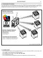
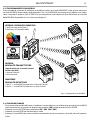
3.14 OPERATION WITH APP “SMARTCOLORS”
Important: WIFIBOX hardware is required to use this app.
WIFIBOX is a new-generation light control system, conceived to obtain an easy and versatile platform for
LED projectors. The signal transmission is managed wired and wireless (through Wi-Fi), both in input and
output, even allowing to control the xtures through a smartphones applications “Smarcolors”, available
for IOS and Android devices. Before using the application, check that all devices are properly congured
with WIFIBOX. For device’s conguration refer to the WIFIBOX manual available on “www.musiclights.it”.

13
SMARTBAT
Fig.9 - Conguration with WIFIBOX
WIFIBOX: SIGNAL INPUT
1) WIFI (with SmartColors App)
2) DMX (with a DMX Controller)
WIFIBOX: TRANSMITTER MODE
(type of channel for data wireless
communication)
1) Manual Channel
2) Auto Channel
SMARTBATHEX: RECEIVER MODE
1) drCH --> WIFIBOX sets on Manual Channel
2) drAU --> WIFIBOX sets on Auto Channel
3.15 OPERATION WITH WIFIBOX
This mode allows you to wirelessly connect more units SMARTBAT, all managed through a unit WIFIBOX
(sold separately). For the unit WIFIBOX, transmitter signal, will set the input signal, WIFI or DMX. For the
conguration of the devices refer to the manual of WIFIBOX available on “www.musiclights.it”.
3.16 DIMMER MODE
• Enter in Dimmer mode to select specic dimming curve, press the button MENU so many times until
shows [dIM], and press the button ENTER to conrm.
• Press the button UP/DOWN to select [OFF - dIM1 - dIM2 - dIM3].
• Press ENTER button to store.
• Press the MENU button to go back or to meet the waiting time to exit the setup menu.

SMARTBAT
14
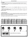
Example 6 DMX channels configuration
Number of
DMX channels
Start address
(example)
DMX Address
occupied
Next possible start
address for unit No. 1
Next possible start
address for unit No. 2
Next possible start
address for unit No. 3
4 33 33-36 37 41 45
6 33 33-38 39 45 51
10 33 33-42 43 53 63
. . . . . . . . . . . .
DMX512 Controller
Fig.10
DMX Address: 33 DMX Address: 51DMX Address: 39 DMX Address: 45
3.17 LINKING
1. Connect the DMX OUT of the master unit via 3-pole XLR cable to the DMX IN of the rst slave unit.
2. Connect the DMX OUT of the rst slave unit to the DMX IN of the second slave unit, etc. until all units
are connected in a chain.
3.18 DMX MODE
• Press the button MENU so many times until shows, [CH4], [CH6] or [CH10] and press the button ENTER to
conrm.
• Press the button UP/DOWN to select the desired DMX address [d001 - d512]. Press and hold to scroll
quickly. Press ENTER button to store.
The tables on page 17 indicate the operating mode and DMX value. The SMARTBAT is equipped with 3
pole XLR connections.
3.19 DMX ADDRESSING
To able to operate the SMARTBAT with a light controller, adjust the DMX start address for the rst a DMX
channel. If e. g. address 33 on the controller is provided for controlling the function of the rst DMX chan-
nel, adjust the start address 33 on the SMARTBAT.
The other functions of the light eect panel are then automatically assigned to the following addresses. At
the next page an example with the start address 33 is shown below:

15
SMARTBAT
Fig.11
Fig.12
3.20 CONNECTION OF THE DMX LINE
DMX connection employs standard XLR connectors. Use shielded pair-twisted cables with 120 imped-
ance and low capacity.
The following diagram shows the connection mode:
ATTENTION
The screened parts of the cable (sleeve) must never be connected to the system’s earth, as this would
cause faulty xture and controller operation.
Over long runs can be necessary to insert a DMX level matching amplier.
For those connections the use of balanced microphone cable is not recommended because it cannot
transmit control DMX data reliably.
• Connect the controller DMX input to the DMX output of the rst unit.
• Connect the DMX output to the DMX input of the following unit. Connect again the output to the input
of the following unit until all the units are connected in chain.
• When the signal cable has to run longer distance is recommended to insert a DMX termination on the
last unit.
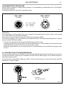
3.21 CONSTRUCTION OF THE DMX TERMINATION
The termination avoids the risk of DMX 512 signals being reected back along the cable when they reach-
es the end of the line: under certain conditions and with certain cable lengths, this could cause them to
cancel the original signals.
The termination is prepared by soldering a 120 1/4 W resistor between pins 2 and 3 of the 5-pin male XLR
connector, as shown in gure.
DMX - OUTPUT
XLR socket
DMX - INPUT
XLR plug
Pin1 : GND - Shield
Pin2 : - Negative
Pin3 : + Positive
Example:
3 pin XLR connector

SMARTBAT
16
3.22 DMX CONTROL
MODE
FUNCTION DMX
Value
4 Ch
1
RED
0~100% 000 - 255
2
GREEN
0~100% 000 - 255
3
BLUE
0~100% 000 - 255
4
WHITE
0~100% 000 - 255
MODE
FUNCTION DMX
Value
6 Ch
1
DIMMER
0~100% 000 - 255
2
RED
0~100% 000 - 255
3
GREEN
0~100% 000 - 255
4
BLUE
0~100% 000 - 255
5
WHITE
0~100% 000 - 255
6
STROBE
No Function
Strobe slow to fast
000 - 010
011 - 255
MODE
FUNCTION DMX
Value
10 Ch
1
DIMMER
0~100% 000 - 255
2
RED
0~100% 000 - 255
3
GREEN
0~100% 000 - 255
4
BLUE
0~100% 000 - 255
5
WHITE
0~100% 000 - 255
6
COLOR COLOR + COLOR TEMPERATURE
No Function
R 100% G 0~100% B 0
R 100%~0 G 100% B 0
R 0 G 100% B 0~100%
R 0 G 100%~0 B 100%
R 0~100% G 0 B 100%
R 100% G 0 B 100%~0
R 100% G 0~100% B 0~100%
R 100%~0 G 100%~0 B 100%
R 100% G 100% B 100% W 100%
Color temperature 1
Color temperature 2
Color temperature 3
Color temperature 4
Color temperature 5
Color temperature 6
Color temperature 7
Color temperature 8
Color temperature 9
Color temperature 10
Color temperature 11
000-010
011-030
031-050
051-070
071-090
091-110
111-130
131-150
151-170
171-200
201-205
206-210
211-215
216-220
221-225
226-230
231-235
236-240
241-245
246-250
251-255
7
STROBE
No Function
Strobe slow to fast
000 - 010
011 - 255
8
AUTO/SOUND PROGRAMS
No Function
Auto Program 1
Auto Program 2
Auto Program 3
Auto Program 4
000-010
011-060
061-120
121 - 180
181 - 240
MODE
FUNCTION DMX
Value
10 Ch
8 Sound show 241 - 255
9
AUTO SPEED
Speed slow to fast 000 - 255
10
DIM MODE
Preset dimmer speed from display menu
Dimmer speed mode o
Dimmer speed mode1 (fast speed)
Dimmer speed mode2 (middle speed)
Dimmer speed mode3 (slow speed)
000-051
052-101
102-152
153-203
204-255

17
SMARTBAT
Fig.13
- 4 - MAINTENANCE
4.1 MAINTENANCE AND CLEANING THE UNIT
• Make sure the area below the installation place is free from unwanted persons during setup.
• Switch o the unit, unplug the main cable and wait until the unit has cooled down.
• All screws used for installing the device and any of its parts should be tightly fastened and should not
be corroded.
• Housings, xations and installation spots (ceiling, trusses, suspensions) should be totally free from any
deformation.
• The main cables must be in impeccable condition and should be replaced immediately even when a
small problem is detected.
• It is recommended to clean the front at regular intervals, from impurities caused by dust, smoke, or
other particles to ensure that the light is radiated at maximum brightness. For cleaning, disconnect the
main plug from the socket. Use a soft, clean cloth moistened with a mild detergent. Then carefully wipe
the part dry. For cleaning other housing parts use only a soft, clean cloth. Never use a liquid, it might
penetrate the unit and cause damage to it.
4.2 FUSE REPLACEMENT
1. Remove the safety cap by a screwdriver.
2. Replace the blown fuse with a fuse of the exact same type and rating.
3. Install the safety cap, and reconnect power.
Fuse

SMARTBAT
18
Battery Guide
New Lithium Battery Initialisation
Any new xture containing a Lithium battery should be initialised when rst purchased to maximise its battery life.
To do this:
1. Fully charge the unit for a minimum of 5 to 6 hours.
2. Fully discharge, then fully recharge the battery.
3. Repeat this cycle another 2 times for optimum battery life.
Maximizing Battery Performance
1. Lithium batteries perform best when in regular use. Long idle periods will reduce the battery life.
2. Recharge the battery at the earliest opportunity, leaving batteries discharged for long periods will reduce battery life.
3. Store units containing Lithium batteries at cool temperatures. High ambient temperatures signicantly reduce the life
of a Lithium battery.
4. Disconnect power from the unit when charging is complete.
5. Do not use xtures whilst charging.
Long term storage
1. Charge your xture’s battery to around 50%. If you store a xture with a fully discharged battery, it could fall into a
deep discharge state. If you store it fully charged, the battery may lose some capacity, leading to shorter battery life.
2. Power down the device to avoid additional battery use.
3. Place your device in a cool, moisture-free environment that’s less than 32° C (90° F).
La pagina si sta caricando...
La pagina si sta caricando...
La pagina si sta caricando...
La pagina si sta caricando...
La pagina si sta caricando...
La pagina si sta caricando...
La pagina si sta caricando...
La pagina si sta caricando...
La pagina si sta caricando...
La pagina si sta caricando...
La pagina si sta caricando...
La pagina si sta caricando...
La pagina si sta caricando...
La pagina si sta caricando...
La pagina si sta caricando...
La pagina si sta caricando...
La pagina si sta caricando...
La pagina si sta caricando...
La pagina si sta caricando...
La pagina si sta caricando...
La pagina si sta caricando...
La pagina si sta caricando...
La pagina si sta caricando...
La pagina si sta caricando...
-
 1
1
-
 2
2
-
 3
3
-
 4
4
-
 5
5
-
 6
6
-
 7
7
-
 8
8
-
 9
9
-
 10
10
-
 11
11
-
 12
12
-
 13
13
-
 14
14
-
 15
15
-
 16
16
-
 17
17
-
 18
18
-
 19
19
-
 20
20
-
 21
21
-
 22
22
-
 23
23
-
 24
24
-
 25
25
-
 26
26
-
 27
27
-
 28
28
-
 29
29
-
 30
30
-
 31
31
-
 32
32
-
 33
33
-
 34
34
-
 35
35
-
 36
36
-
 37
37
-
 38
38
-
 39
39
-
 40
40
-
 41
41
-
 42
42
-
 43
43
-
 44
44


ProLights Wireless battery operated portable uplighter Manuale utente
- Categoria
- Stroboscopi
- Tipo
- Manuale utente
- Questo manuale è adatto anche per
in altre lingue
Documenti correlati
-
ProLights Wireless battery operated portable uplighter Manuale utente
-
-
-
-
-
-
-
-
-
