
THE APOLLO INTELLIGENT METER SERIES
MODEL IMT INSTRUCTION MANUAL
imtCVR-k.QXD 4/4/05 2:32 PM Page 1

INTRODUCTION
The Intelligent Meter for Thermocouple Inputs (IMT) is another unit in our
multi-purpose series of industrial control products that are field-programmable to
solve multiple applications. This series of products is built around the concept that
the end user has the capability to program different personalities and functions
into the unit in order to adapt to different indication and control requirements.
The Intelligent Thermocouple Meter which you have purchased has the same
high quality workmanship and advanced technological capabilities that have
made Red Lion Controls the leader in today’s industrial market.
Red Lion Controls has a complete line of industrial indication and control
equipment, and we look forward to being of service to you now and in the future.
CAUTION: Read complete instructions
prior to installation and operation of the unit.
CAUTION: Risk of electric shock.
imtCVR-k.QXD 4/4/05 2:32 PM Page 2

Table of Contents
SAFETY INFORMATION ······························································ 3
Safety Summary ·································································· 3
GENERAL DESCRIPTION ···························································· 4
Theory Of Operation ······························································· 4
Block Diagram ···································································· 5
PROGRAMMING & OPERATING THE IMT ··············································· 6
Programming The IMT ····························································· 6
Module #1 - Program Thermocouple Type, Scale And Resolution ·························· 8
Module #2 - Program Temperature Display Offset And Slope ····························· 8
Module #3 - Program Functions Accessible w/ Front Panel Lockout ························ 8
Module #4 - Program Digital Filter And Remote Input ··································· 10
Module #5 - Program Integrator/Totalizer ············································· 12
Module #6 - Program Alarm/Setpoint ················································ 13
Module #7 - Program Serial Communications ········································· 15
Module #8 - Program Re-Transmitted Analog Output ··································· 16
Module #9 - Service Operations ···················································· 16
Operating The IMT ······························································· 18
Quick Programming ······························································ 18
Factory Configuration ····························································· 19
Programming Example ···························································· 20
Temperature Monitoring/Offset Example ············································· 21
Process Control Example ·························································· 22
INTEGRATOR / TOTALIZER / PEAK / VALLEY / SLOPE / OFFSET (Optional) ··············· 23
Integrator/Totalizer ······························································· 23
Integrator/Totalizer Example ······················································· 23
Basic Set-Up ································································· 23
Integrator/Totalizer Set-Up ······················································ 23
Peak/Valley ····································································· 24
Offset And Slope Display Temperature ··············································· 25
ALARMS (Optional) ································································ 26
20 mA CURRENT LOOP SERIAL COMMUNICATIONS (Optional) ·························· 27
General Description ······························································ 27
-1-

Communication Format ··························································· 27
Sending Commands To The IMT ···················································· 28
Command String Examples ····················································· 28
Receiving Data From The IMT ······················································ 30
CURRENT LOOP INSTALLATION ····················································· 31
Wiring Connections ······························································· 31
Serial Terminal Descriptions (TBC) ·················································· 31
Serial Communications Example ···················································· 32
Process Controlling System ····················································· 32
RE-TRANSMITTED ANALOG OUTPUT (Optional) ······································· 33
Analog Output Calibration ························································· 34
APPENDIX “A” - INSTALLATION & CONNECTIONS ····································· 35
Installation Environment ··························································· 35
Panel Installation ······························································ 35
Select AC Power (115/230 VAC) ···················································· 35
EMC Installation Guidelines ························································ 36
Power Wiring ································································· 37
Signal Wiring (TC Sensor) ······················································ 37
User Input Wiring ····························································· 37
Output Wiring ································································· 37
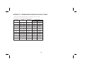
APPENDIX “B” - THERMOCOUPLE RANGE AND ACCURACY TABLE ····················· 38
APPENDIX “C” - SPECIFICATIONS AND DIMENSIONS ··································· 39
APPENDIX “D” - TROUBLESHOOTING GUIDE ········································· 41
APPENDIX “E” - PROGRAMMABLE FUNCTIONS ······································· 42
APPENDIX “F” - ORDERING INFORMATION ··········································· 44
-2-

SAFETY INFORMATION
SAFETY SUMMARY
All safety related regulations, local codes and instructions that appear in
the manual or on equipment must be observed to ensure personal safety and to
prevent damage to either the instrument or equipment connected to it. If
equipment is used in a manner not specified by the manufacturer, the
protection provided by the equipment may be impaired.
Do not use this unit to directly command motors, valves, or other actuators
not equipped with safeguards. To do so can be potentially harmful to persons
or equipment in the event of a fault to the unit.
DEFINITION OF TERMS
INSTALLATION CATEGORY (overvoltage category) I:
Signal level, special equipment or parts of equipment,
telecommunication, electronic, etc. with smaller transient overvoltages
than Installation Category (overvoltage category) II.
INSTALLATION CATEGORY (overvoltage category) II:
Local level, appliances, portable equipment, etc. with smaller transient
overvoltages than Installation Category (overvoltage category) III.
-3-

GENERAL DESCRIPTION
The Apollo Intelligent Thermocouple Meter accepts inputs from standard
thermocouples and precisely linearizes them. A full 6-digit display
accommodates a wide range of temperature inputs and holds large
totalization values. State-of-the-art digital circuitry virtually eliminates
errors due to drift. The unit automatically compensates for cold junction,
NBS linearity and the meter’s zero and span. A full complement of option
packages is available to fulfill many process applications.
The indicator features a readout choice of either Fahrenheit or Celsius with
0.1 or 1 degree of resolution. English Style display prompts aid the operator
through set-up and operation. With a few simple steps the unit can be engaged
as a millivolt meter by programming “mV” for thermocouple type (enter 8 in
“Pro 1”). This mode is useful in monitoring and displaying the actual voltage
produced at the thermocouple probe junction as an aid in troubleshooting for
a possible faulty thermocouple probe. A front panel lock-out menu protects
set-up data and operation modes from unauthorized personnel.
Programmable digital filtering enhances the stability of the reading. The
programmable remote input “E1-CON” pin can be utilized to control a
variety of functions, such as totalizing, alarm control, peak/valley readings,
display hold, or temperature offset operations. All set-up data is stored in
E
2
PROM, which will hold data for a minimum of 10 years without power.
An optional integrator (totalizer) can be used to totalize or integrate
temperatures up to a maximum display value of 999,999. It features
independent scaling, decimal point selection and a low temperature cut-out to
suit a wide variety of temperature integration applications. The
programmable remote input “E2-CON” pin is included with this option and
can be utilized to control a variety of functions, such as totalizing, alarm
control, peak/valley readings, display hold or temperature offset operations,
simultaneously with “E1-CON” pin. Peak/valley (max/min) reading
memory, display hold and programmable temperature offset functions are
included with this option and they are easily recalled and controlled by either
the front panel or a remote input. All readings are retained at power-down.
Optional dual relays with parallel solid state outputs are fully
programmable to operate in a wide variety of modes to suit many control or
alarm applications.
Optional 20 mA loop, bi-directional serial communications provides
computer and printer interfacing to extend the capabilities of the indicator.
More than one unit can be connected in the loop with other RLC products
which have serial communications capabilities.
An optional 4 to 20 mA or 0 to 10 VDC re-transmitted analog output can be
scaled by the user to interface with a host of recorders, indicators and
controllers. The type of analog output is determined by the model ordered.
(See Ordering Information for available models.) The indicator has several
built-in diagnostic functions to alert operators of most malfunctions.
Extensive testing of noise interference mechanisms and full burn-in make the
indicator extremely reliable in industrial environments. The die-cast front
bezel meets NEMA 4/IP65 requirements for washdown applications.
THEORY OF OPERATION
The IMT employs a microprocessor to perform the A/D conversion on the
input signal via a voltage-to-frequency converter. It digitally scales the
result, corrects for meter drift which may be present and then displays the
result in a 6-digit display (4 for temperature, 6 for totalizer). The inputs are
filtered to enhance the stability of the display. A non-volatile E
2
PROM
memory device provides permanent data retention for operating variables.
The display consists of drivers and 6-digit solid-state LEDs. The alarm option
employs opto-isolators to isolate the open collector devices from meter
common. Operating in parallel, the relays are type Form-C and are rated at
5-amps. The serial communication option features a built-in 20 mA current
source and complete opto-isolation. The analog option features a 12-bit DAC
and provides an output signal that is digitally scaled. The re-transmitted
output is isolated from meter common.
-4-

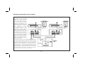
-5-
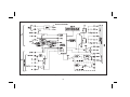
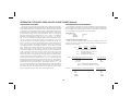
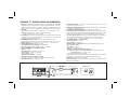
Note: Analog, Serial, and SNK output options are isolated from signal common at a working voltage of 50 V. The commons should NOT be tied together.
FIG. 1:
BLOCK DIAGRAM

PROGRAMMING & OPERATING THE IMT
PROGRAMMING THE IMT
Although the unit has been programmed at the factory, the set-ups will
generally have to be changed to suit the application. Basic set-up is complete
after unit of temperature scale selection, thermocouple type selection,
decimal point selection, and digital filtering level selection have been made.
Before actually trying to program the indicator, it is advisable to organize
all the data for the programming steps to avoid any possible confusion and to
read the programming procedure entirely before proceeding.
To set-up the indicator, connect AC power and signal wires as outlined in
the connections section (Appendix “A”). Remove the jumper wire (if
installed) from TBA #3 (PGM. DIS.). This will allow the operator to enter and
modify all of the indicator’s parameters. Press the front panel button labeled
“P”, momentarily. Briefly, the display will show “Pro” alternately flashing
with “0”. This is the indicator’s programming mode. The programming mode
is divided into sections, numbered 0-9, each of which can be individually
accessed. The front panel “UP” and “DOWN” arrow buttons can be used to
select one of these numbers and the “P” button can be used to enter the
selected programming module. In all of the programming modules, “UP” and
“DOWN” are used to either select from a list of choices or enter a value. The
“P” button is used to save the new value and progress to the next step within a
module (Note: the new value takes effect when “P” is pressed). Upon
completion of a module, the indicator returns to the “Pro” < > “0” stage.
Pressing the “P” button at this point causes the indicator to display “End”
after which the indicator returns to the normal display mode. The following
table explains the basic function of each step.
Note: < >This indicates that the display will alternate between the English
prompt and the actual data.
-6-

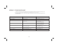
DISPLAY RESULT OF “P” BUTTON
“Pro” < > “0” - Causes the indicator to return to normal display mode. Any
changes to set-up data are permanently stored in the E
2
PROM.
“Pro” < > “1” - Entry into this module allows the user to select the
thermocouple type, temperature scale (Fahrenheit “F” or Celsius “C”),
and display decimal point position. User keys in 0 or 0.0 degree resolution.
“Pro” < >“2” - Entry into this module allows the user to select non-standard
display slope and display offset values. This enables the meter to be
”scaled" to a calibrated temperature thermocouple. (This scaling is NOT
required for most applications.)
“Pro” < > “3” - Module #3 allows the user to program what can be accessed
from the front panel when the PGM. DIS. (Program Disable, TBA #3) pin
is connected to common. This feature protects critical set-up data from
accidental modification while allowing access to setpoints and other
functions. The front panel lock-out menu (quick programming) includes
setpoint modification, integrator/totalizer resetting, peak/valley
resetting and display offset modification.
Note: The term “Quick Programming” is used to refer to the ability to
change the information that can be accessed from the front panel
when the “PGM. DIS.” terminal is connected to “COMM.”.
DISPLAY
RESULT OF “P” BUTTON
“Pro” < > “4” - Module #4 programs the digital filtering level and the function
of the remote input “E1-CON” pin (TBA #4) and if the totalizer option is
installed the remote input “E2-CON” pin (TBC #1). The functions of the
remote E1 and E2 pins are the same and include display hold, peak/valley
modes, totalizer reset, alarm reset, temperature offset, reading
synchronization or print request.
“Pro” < > “5” - This module sets the decimal point, time base, scale factor and
low temperature disable function for the optional integrator/totalizer.
“Pro” < > “6” - This module allows programming for the basic configuration of
the alarm option. The programming includes HI/ LO acting, tracking, alarm
display, latched or auto-reset, assignment to either the input or the
integrator/totalizer, and alarm and hysteresis values.
“Pro” < >“7” - Module #7 is the serial communication parameter
program-ming. Baud rate, unit address, print request function and condensed
prints are all programmable.
“Pro” < > “8” - This module allows digital scaling of the retransmitted analog
output. Display values that correspond to 4 mA or 0 VDC and 20 mA or 10
VDC are keyed-in to scale the output and it may be assigned to either the input
or the integrator/totalizer.
“Pro” < > “9” - This module is the service operations calibration sequence and is
not normally accessed by the user. This step re-calibrates the basic input and
the cold junction temperature and is used to compensate for long-term drift.
Execution of this module should be done by technicians with the proper
equipment in accordance with a maintenance plan of yearly recalibrations. A
code number entry step is used to protect from inadvertent entries. Also, there
is a number of other access codes, which provide test and set-up changes as an
aid in troubleshooting.
-7-

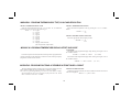
MODULE #1 - PROGRAM THERMOCOUPLE TYPE, SCALE AND RESOLUTION
SELECT THERMOCOUPLE TYPE
Select the desired thermocouple type. (see appendix “B” for additional
information on thermocouple types and ranges)
“tYPE” < > “0” - Type T
“1” - Type E
“2” - Type J
“3” - Type K
“4” - Type R
“5” - Type S
“6” - Type B
“7” - Type N
“8” - Engages millivolt mode
(not cold junction compensated)
If a totalizer option is installed, the offset and slope can be programmed for
various temperature probe differences. Reference offset and slope display
temperature section for more details
This programming module programs what is accessible through the front
panel when the PGM. DIS. pin is connected to common (COMM.).
Note: The term “Quick Programming” is used to refer to the ability to change
the information that can be accessed from the front panel when the “PGM.
DIS.” terminal is connected to “COMM.”.
DISPLAY ALARM VALUES
If the alarm option is installed, this selects whether the alarm values will or
will not be displayed.
“dSP AL” < > “yES” or “NO”
-8-
SELECT TEMPERATURE SCALE
Select the desired temperature scale by pressing the “UP” or “DOWN”
button.
“SCALE” < > “F”
“C”
SELECT DECIMAL POINT POSITION
Select the appropriate decimal point position.
“ dECPNt” < > “0”
“0.0”
To Program:
Select the desired temperature display slope value by pressing the “UP” or
the “DOWN” button.
“SLOPE” < > “0.0001” to “9.9999” (ex. 1.0309)
Select the desired temperature display offset value by pressing the “UP” or
the “DOWN” button.
“OFFSEt” < > “-999” to “9999” (ex. -17.5)
MODULE #2 - PROGRAM TEMPERATURE DISPLAY OFFSET AND SLOPE
MODULE #3 - PROGRAM FUNCTIONS ACCESSIBLE W/ FRONT PANEL LOCKOUT

ENTER ALARM VALUES =
If “YES” was selected for display alarm values, this will select if alarm
values may be modified from the front panel. (If “NO” was selected for
display alarm values, then this step will default to “NO” and will not be
displayed for selection.)
“ENt AL” < > “yES” or “NO”
DISPLAY HYSTERESIS VALUES
If the alarm option is installed, this selects whether the hysteresis values
will or will not be displayed.
“dSPHYS” < > “yES” or “NO”
ENTER HYSTERESIS VALUES =
If “YES” was selected for display hysteresis values, this selects whether
hysteresis values may be modified from the front panel. (If “NO” was
selected for display hysteresis value, then this step will default to “NO” and
will not be displayed for selection.)
“ENtHYS” < > “yES” or “NO”
RESET LATCHED ALARMS
If the alarm option is installed and if either alarm is programmed to latch,
this will select if a latched alarm(s) can be reset from the front panel.
“rSt AL” < > “yES” or “NO”
DISPLAY PEAK/VALLEY MEMORY BUFFER
If the integrator/totalizer option is installed, this selects whether peak and
valley buffers will be displayed.
“dSPbUF” < > “yES” or “NO”
RESET PEAK/VALLEY MEMORY BUFFER =
If “YES” was selected for the previous step, this selects whether the peak
and valley buffers may be reset from the front panel. (If “NO” was selected,
then this step defaults to “NO” and will not be displayed for selection.)
“rStbUF” < > “yES” or “NO”
SELECT DISPLAY*
If the integrator/totalizer option is installed, this selects whether the
display can be switched from input display to total display and from total
display to input display.
Note: When “NO” is selected, whatever display (Input or total) is shown, will be
the only display accessible.
“SELdSP” < > “yES” or “NO”
RESET TOTAL*
If the Integrator/Totalizer option is installed, this selects whether the total
can be reset from the front panel.
“rSttOt” < > “yES” or “NO”
TEMPERATURE OFFSET VALUE =
If the Integrator/Totalizer/Peak/Valley/Temperature Offset option is
installed, this selects whether the programmed offset value will be displayed.
“dsPOFF” < > “yES” or “NO”
ENTER OFFSET VALUE =
If “YES” was selected for the previous step, this selects whether the offset
value can be entered from the panel. (If “NO” was selected, then this step
defaults to “NO” and will not be displayed for selection.)
“ENtOFF” < > “yES” or “NO”
Depending on functions selected under Pro 3 and Pro 6, alarms, hysteresis,
peak, valley and offset values can be monitored and/or changed when PGM.
DIS. is tied to COMM. This provides a “QUICK PROGRAMMING” method
for “day to day” process changes. (See QUICK PROGRAMMING SECTION
for more details.)
= Note: This sequence may be locked-out due to other programmed sequences.
* This function operates independent of the state of the “PGM. DIS.” pin.
-9-

MODULE #4 - PROGRAM DIGITAL FILTER AND REMOTE INPUT
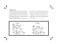
PROGRAM DIGITAL FILTERING
If the displayed process signal is difficult to read due to small process
variations or noise, increased levels of filtering will help to stabilize the
display. This programming step may be used in conjunction with display
rounding programming (PRO1&2)tohelp minimize this effect. The digital
filter used is an “adaptive” filter. That is, the filter coefficients change
dynamically according to the nature of the input signal. This feature
simultaneously allows the filter to settle quickly for large input changes while
providing a stable display reading for normal process variations. Because of
the adaptive nature of the filter, it cannot be characterized in terms of a time
constant. The following table lists the maximum settling time for a step input
to within 99% of the final value.
Filter Value Settling Time (99%)
“FILtEr” < > “0” - no digital filtering 1.5 sec.
“1” - normal filtering 2 sec.
“2” - increased filtering 6 sec.
“3” - maximum filtering 13 sec.
PROGRAM FUNCTION OF E1-CON AND OPTIONAL E2-CON
PIN
The function of the remote input “E1-CON” pin (TBA #4) and, if the
totalizer option is installed, the remote input “E2-CON” pin (TBC #1) are the
same. Functions are activated, as described in the appropriate function, when
connected to signal common (TBA #5). Whether a function is edge or level
activated it must be held low for a minimum of 20 msec in order for the
function to occur. The remote input pins can be used simultaneously and with
any combination of functions. When pins are tied together and activated,
E1-CON function is generally performed first.
“E1-CON”< > “0” - If the Integrator/Totalizer/Peak/Valley/Display Offset
option is installed, a negative going edge offsets the displayed
temperature to zero. (At this time the E-Pin is activated, the value of the
actual temperature being displayed is placed in the location of the display
offset value. To bring the unit back into the normal temperature display
mode, reset the offset value to zero via the front panel.)
“1” - If the Integrator/Totalizer option is installed, a negative going edge
resets the contents of the Integrator/Totalizer to zero.
Integration/Totalization commences regardless of the state of the input.
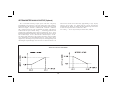
“2” - If the Integrator/Totalizer option is installed, a negative going edge
resets the contents of the Integrator/Totalizer to zero and allows
Integration/Totalization as long as input is low. If the input goes high,
Integration/Totalization is stopped and the contents are saved. This acts
as a Integration/Totalization enable control from time T1 to T2.
“3” - A low level allows Integration/Totalization as long as the input is low.
If the input goes high, totalization is stopped and the contents are saved.
This acts as a totalization enable control from time T1 to T2.
“4” - A low level holds the display (display hold). While this input is low,
the indicator continues to process the input signal and drive the alarms,
Integrator/Totalizer, etc. with the actual signal. The contents of the
Integrator/Totalizer are stored at the same time the input display is held.
Note: If display hold is activated, and input value is requested via serial,
the value on the display will be sent instead of the actual input value
at that time.
“5” - If the Integrator/Totalizer option is installed, a negative going edge
resets both peak and valley buffers.
Note: If P/V is called up, a change will not appear on the display until the
next time the P/V is called up.
“6” - If the Integrator/Totalizer option is installed, a negative going edge
resets only the peak buffer and the indicator enters a peak reading display
mode as long as the input is low. If the input goes high, peak detection and
indication are stopped and the last peak reading is retained.
“7” - If the Integrator/Totalizer option is installed, a negative going edge
resets only the valley buffer and the indicator enters a valley reading
display mode as long as the input is low. If the input goes high, valley
detection and indication are stopped and the last valley reading is retained.
-10-

“8” - If the alarm option is installed, a negative going edge resets the
latched alarm(s).
“9” - If the alarm option is installed, a low level resets a latched or
unlatched alarm into its inactive state. This provides manual override of
alarms for system start-up and other unusual events such as system
testing.
“10” - A negative going edge toggles the display between ”input" and
“total” (from input to total, or vice versa). No action is taken on the
positive going edge.
“11” - A negative going edge zeros (tares) the input signal and adds the
value that was in the input display to the totalizer value, every time this
operation is performed. The time-base, scale factor and low cut-out in
“Module #5” are in affect disabled, when this function is selected.
“12” - Display hold with offset. A negative going edge offsets (zeros) the input
signal. Prior to the offset operation, the input signal is saved and held
(display hold) as long as the remote input pin is low. On the positive edge,
the input display will show zero. If there is an increase to the input signal
while the remote input is low, the display will reflect (show) the increase at
the positive edge.
“13” - Instrument reading synchronization. A low level disables all meter
operations (alarms, total, analog out, etc.). A positive edge resets the start
of the A/D conversion, to allow synchronization with external processes
and controls. While in this function, the other E-CON pin is operational.
“14” - Print request. Transmits data according to the print options that have
been selected in Program Module #7. If the low time exceeds 800 msec, a
second print-out may occur.
“E2-CON”<>Ifthetotalizer option is installed, E2-CON has the same
programmable functions as E1-CON.
-11-

MODULE #5 - PROGRAM INTEGRATOR/TOTALIZER
Programming for the integrator/totalizer consists of four programming
steps: totalizer decimal point position, time base, scale factor and low
temperature disable. Note that the decimal point position of the totalizer can
be set independent of the decimal point position of the scaled input signal.
The integrator/totalizer will roll over and flash when the total exceeds,
999999 or -99999, indicating an overflow condition. Reverse signal input
will cause the totalizer value to count in the opposite direction and eventually
no longer be in an overflow condition.
PROGRAM DECIMAL POINT POSITION
Enter the decimal point position for the integrator/totalizer.
“dECPNt” < > “0”
“0.0”
“0.00”
“0.000”
“0.0000”
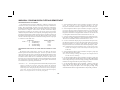
PROGRAM INTEGRATOR/TOTALIZER TIME BASE
The time base determines the rate at which readings increase. The
integrator/totalizer display is updated 2 times per second regardless of time
base selected, but longer time bases decrease the magnitude of each increase.
The three time bases are per second, per minute and per hour. A constant input
temperature of 100°, for example, would integrate/totalize to 100° in one
second (with a TB of 1 sec.), 100° in one minute (with a TB of 1 min.), and 100°
in one hour (with a TB of 1 hr.). (Note: Input changes cannot be made
synchronous to the display by programming E1 or optional E2-CON pin for
function 13, instrument reading synchronization.) A multiplying scale factor
may be used to span the standard time ranges (or divide if scale factor 1). The
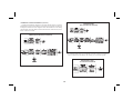
following equation expresses the integration/totalization process.
S.F. =
D.T.
x
T.B.
x
D.T.D.P.
T.D. TIME T.D.D.P.
S.F. = Programmable Scale Factor
D.T. = Desired Totalizer value for a
fixed time duration
T.B. = Programmable Time Base
TB = If Program Select Number Chosen Is:
Enter in Formula
“0” for sec. 1
“1” for min. 60
“2” for hr. 3600
T.D. = Temperature Display Value
TIME = Actual Time period in seconds
D.T.D.P. = Desired Totalizer Value Decimal Point
Enter in Formula
01
0.0 10
0.00 100
0.000 1000
0.0000 10000
T.D.D.P. = Temperature Display Value Decimal Point
Enter in Formula
01
0.0 10
“tbASE” < > “0” - per second
“1” - per minute
“2” - per hour
PROGRAM THE INTEGRATOR/TOTALIZER SCALE FACTOR
As explained in the previous programming step, a multiplying scale factor
can be used to scale the update rate as required. This may be used to span the
standard ranges. A scale factor of “1.000” has no effect on the standard ranges.
“SCLFAC” < > “0.001” to “100.000”
PROGRAM THE LOW-END CUTOUT (low temperature level
disable)
In order to prevent false integration/totalization in situations where
integration/totalization is undesirable, a programmable setpoint can be used
to disable integration/totalization when the input temperature falls below this
low-end cutout level.
“Lo-cut” < > “-999” to “9999”
-12-

MODULE #6 - PROGRAM ALARM/SETPOINT
If the alarm option is installed, this module is used to configure the
operation of the alarms to a variety of combinations. The programmable
options are HI/LO acting, auto/manual reset (latching), tracking, assignment
to input or integrator/totalizer, display alarms, alarm values and hysteresis
(deadband) values.
ALARM TRACKING
With alarm tracking, whenever alarm #2 is changed, alarm #1 will also
change so that the offset between alarm #2 and alarm #1 remains the same.
This is useful for hierarchical setpoints (pre-alarm and alarm) when one
change applies to both alarm values. When programming from the front
panel, tracking only occurs when PGM. DIS. is low (front panel lock-out
mode, alarm #1 will not appear). Tracking will always occur if alarm #2 is
modified via serial communications independent of PGM.DIS.
“trAc” < > “yES” or “NO”
DISPLAY ALARMS
If display alarm is desired, a message will flash on the display every 5-10
secs when an alarm activates. For alarm 1, the message will flash “AL1 on”
and alarm 2 will flash “AL2 on”, this warns an operator of an alarm condition.
The message will stop when the unit is no longer in an alarm condition.
“dISP” < > “yES” or “NO”
AUTO OR MANUAL RESET FOR ALARM #1
The reset action of alarm #1 may be programmed to reset automatically
(unlatched) or be programmed to require a manual reset (latched) through
either a remote input (E1-CON or optional E2-CON) or through the front
panel. Latched alarms are usually used when an operator is required to take
some action for the alarm condition.
“LAtC-1” < > “yES” or “NO”
ALARM #1 ASSIGNMENT TO INPUT OR
INTEGRATOR/TOTALIZER
Alarm #1 may be programmed to activate on either the input or the
integrator/totalizer value. If the integrator/totalizer option is not installed,
this step defaults to the input.
“ASN-1” < > “INPUt” or “totAL”
PROGRAM VALUE FOR ALARM #1
The range of the alarm value is -999 to 9,999 if the alarm “assignment” is
programmed for “INPUt”. If “assignment” is set for “totAL”, then the range is
-99,999 to 999,999.
“AL-1” < > “-99999” to “999999”
PROGRAM HYSTERESIS VALUE FOR ALARM #1 (Cannot be
programmed if alarm latch is programmed)
The hysteresis (deadband) value for alarm #1 may be programmed from 1
to 9,999 if the alarm “assignment” is programmed for “INPUt”. If
“assignment” is set for “totAL”, then the range is 1 to 999,999. The value is
either added to or subtracted from the alarm value depending on whether the
alarm is high or low acting. (See “alarm” section for operation.)
“HYS-1” < > “1” to “999999”
ALARM #1 HIGH OR LOW ACTING
The action of alarm #1 may be programmed to activate either when the
signal goes above the alarm value (high acting) or goes below it (low acting).
“Act-1” < > “HI” or “LO”
-13-

MODULE #6 - PROGRAM ALARM / SETPOINT (Cont’d)
AUTO OR MANUAL RESET FOR ALARM #2
The reset action of alarm #2 may be programmed to reset automatically
(unlatched) or be programmed to require a manual reset (latched) through
either a remote input (E1-CON or optional E2-CON) or through the front
panel. Latched alarms are usually used when an operator is required to take
some action for the alarm condition.
“LAtC-2” < > “yES” or “NO”
ALARM #2 ASSIGNMENT TO INPUT OR
INTEGRATOR/TOTALIZER
Alarm #2 may be programmed to activate on either the input or the
Integrator/Totalizer value. If the Integrator/Totalizer option is not installed,
this step defaults to the input.
“ASN-2” < > “INPUt” or “totAL”
PROGRAM VALUE FOR ALARM #2
The range of the alarm value is -999 to 9,999 if the alarm “assignment” is
programmed for “INPUt”. If “assignment” is set for “totAL”, then the range is
-99,999 to 999,999.
“AL-2” < > “-99999” to “999999”
PROGRAM HYSTERESIS VALUE FOR ALARM #2 (Cannot be
programmed if alarm latch is programmed)
The hysteresis (deadband) value for alarm #2 may be programmed from 1
to 9,999 if the alarm “assignment” is programmed for “INPUt”. If
“assignment” is set for “totAL”, then the range is 1 to 999,999. The value is
either added to or subtracted from the alarm value depending on whether the
alarm is high or low acting. (See “alarm” section for operation.)
“HYS-2” < > “1” to “999999”
ALARM #2 HIGH OR LOW ACTING
The action of alarm #2 may be programmed to activate either when the
signal goes above the alarm value (high acting) or goes below it (low acting).
“Act-2” < > “HI” or “LO”
Note: Depending on options selected under Pro 3 and Pro 6, alarms, hysteresis,
peak, and valley values can be monitored and/or changed when PGM. DIS. is
tied to COMM. This provides a “QUICK PROGRAMMING” method for
“day to day” process changes. (See QUICK PROGRAMMING SECTION for
more details.)
-14-

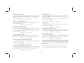
MODULE #7 - PROGRAM SERIAL COMMUNICATIONS
Several programmable parameters must be programmed before serial
communication can occur.
BAUD RATE
Select one of the baud rates from the list to match the baud rate of the
printer, computer, controller, etc.
“bAud” < > “300” - 300 baud
“600” - 600 baud
“1200” - 1200 baud
“2400” - 2400 baud
UNIT ADDRESS NUMBER
To allow multiple units to communicate on the 20 mA loop, different address
numbers must be assigned to each unit. If only one unit is on the loop, an
address of “0” may be given, eliminating the need for the address command.
“AddrES” < > “0” to “99”
PRINT REQUEST FUNCTION
A selection of print operations can be programmed. A print operation
occurs when a print request is activated via E1-CON (TBA #4) or optional
E2-CON (TBC #1) pin, or a “P” command is sent from a terminal via the
serial communications option. If the option to which a particular print code
applies is not installed, then that parameter will not be printed.
If the totalizer is overfowed an asterisk (*) will precede the digits that are
printed (ex. *000127 positive overflow, -*00127 negative overflow). If the
temperature exceeds the positive range of the unit, the print-out will show
“OLOLOL”. An open sensor will print out “OPEN”. If the temperature
exceeds the negative range, the print-out will show “ULULUL”. A shorted
sensor will print out “SHOrt”.
“Print” < > “0” - temperature input signal
“1” - temperature input signal, peak, valley and offset
“2” - temperature input signal, alarm 1, and alarm 2
“3” - temperature input signal, alarm 1, alarm 2,
hysteresis 1, hysteresis 2, peak, valley, and offset
“4” - totalizer
“5” - temperature input signal and totalizer
“6” - temperature input signal, totalizer, peak, valley,
and offset
“7” - totalizer, alarm 1, and alarm 2
“8” - temperature input signal, totalizer, alarm 1, alarm 2
“9” - temperature input signal, totalizer, alarm 1, alarm 2,
hysteresis 1, hysteresis 2, peak, valley, and offset
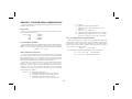
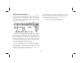
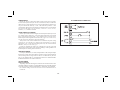
FULL OR ABBREVIATED TRANSMISSION
When transmitting data, the IMT can be programmed to suppress the
address number, mnemonics and some spaces, if desired by selecting “NO”.
A selection of “NO” results in faster transmission. This feature may be
helpful when interfacing with a computer. When interfacing to a printer, a
“yES” response is usually desirable.
“FULL” < > “yES” or “NO”
An example of full and abbreviated transmission is shown below:
2 TC -125.7F <CR> <LF> Full transmission
-125.7 <CR> <LF> Abbreviated transmission
-15-

MODULE #8 - PROGRAM RE-TRANSMITTED ANALOG OUTPUT
This programming module allows digital scaling of the 4 to 20 mA or 0 to 10
VDC analog output. The type of analog output is determined by the model
ordered. (See Ordering Information for available models.) The display value at
which 4 mA or 0 VDC and the display value at which 20 mA or 10 VDC are
transmitted are keyed-in. The indicator automatically calculates slope and
intercept values to complete the scaling. The analog output then follows the
calculated display value and as such will update every measurement cycle. The
output may also be programmed to proportionally re-transmit the contents of
the integrator instead of the input. Reverse acting output can be achieved by
programming the “high” display value for the “AN-Lo” programming step and
the “low” display value for the “AN-HI” step.
Note: DO NOT ADJUST THE ANALOG OUTPUT POTS ON THE BACK OF
THE UNIT. Fine offset and span adjustment pots are externally accessible to
compensate for small drifts in the output. These pots have been set at the
factory and do not normally require adjustment.
ANALOG OUTPUT SOURCE
Program whether the input or the integrator/totalizer will serve as the basis
for the analog output signal. If the integrator/totalizer option is not installed,
then this step defaults to “INPUt”.
“ASIN” < > “INPUt” or “totAL”
ANALOG OUTPUT LO DISPLAY VALUE
Program the display value at which the analog output transmits 4 mA or 0
VDC. If “INPUt” was selected for “ASIN”, the range is -999 to 9999. If
“totAL” was selected, then the range is -99,999 to 999,999.
“AN-Lo” < > “-99999” to “999999”
ANALOG OUTPUT HI DISPLAY VALUE
Program the display value at which the analog output transmits 20 mA or
10 VDC. If “INPUt” was selected for “ASIN”, the range is -999 to 9999. If
“totAL” was selected, then the range is -99,999 to 999,999.
“AN-HI” < > “-99999” to “999999”
-16-
MODULE #9 - SERVICE OPERATIONS
The indicator has been fully calibrated at the factory. If the unit appears to
be indicating incorrectly or inaccurately, refer to the troubleshooting section
before attempting this procedure.
When re-calibration is required (generally every 2 years), this procedure
should only be performed by qualified technicians using appropriate
equipment. A precision thermometer (RTD, thermistor or similar type
(accuracy of ± 0.3° C) and an accurate voltage source (0.01%) are required.
The procedure consists of setting the cold junction temperature and
applying accurate voltages to the indicator in a series of three steps. Allow a
30 minute warm-up before starting this procedure.
Note: Once the access code has been entered, there is no exiting the program
module without completing the calibration procedure. Removing power to
the meter cancels the procedure.

MODULE #9 - SERVICE OPERATIONS (Cont’d)
COLD JUNCTION TEMPERATURE CALIBRATION
1. Connect a calibrated thermocouple (types T, E, J, K, or N only) to the panel
meter. Select the thermocouple type used in programming.
2. Connect the reference thermometer to the measuring end of the thermocouple.
The two probes should be shielded from air movement and allowed sufficient
time to equalize in temperature. (As an alternative, the IMT thermocouple
probe may be placed in a calibration bath of known temperature.)
3. From the normal indicator display mode, compare the display temperature to that
of the reference thermometer. Allow 10 minutes for the temperature to equalize.
The meter and the reference thermometer should agree to within 1° F (0.6° C)
4. If cold junction re-calibration is necessary (temperature out of tolerance),
enter Module #9, code 48. At the “CJC” display, key-in the new cold junction
temperature according to the formula:
New Cold Junction Reading = Old Cold Junction Reading + Difference
Difference = Reference Thermometer Temperature - Meter Display Temp.
5. Check results by repeating steps 1, 2, and 3.
VOLTAGE CALIBRATION
1. Enter Module #9, code 48.
2. Step through “CJC” until CAL <> yes/no appears. Select yes.
ENTER 1st CALIBRATION VOLTAGE
Apply 0.000 mV to the input by shorting the signal wires. Allow to
stabilize for 20 seconds before pressing “P”.
“StEP 1” (Press “P”)
ENTER 2nd CALIBRATION VOLTAGE
Apply 30.000 mV to the input. Allow to stabilize for 20 seconds before
pressing “P”.
“StEP 2” (Press “P”)
ENTER 3rd CALIBRATION VOLTAGE
Apply 60.000 mV to the input. Allow to stabilize for 20 seconds before
pressing “P”.
“StEP 3” (Press “P”)
Indicator calibration is complete. It is recommended that calibration be
checked by selecting mV indication mode, and verifying unit accuracy at
various points over the range of the unit (-10 to +80 mV).
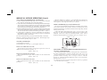
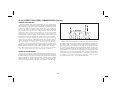
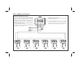
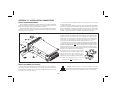
SERIAL HARDWARE (loop-back) DIAGNOSTICS
The internal serial communications hardware in the IMT can be tested to
verify proper operation. The procedure consists of connecting the Serial
Input (SI), Serial Output (SO), and 20 mA Source into a simple loop, and then
entering an access code.
Connect the IMT as shown below. Enter “Pro 9”, key-in “Code 39”, and
then press “P”. If the serial communication hardware is OK, “PASS” will be
displayed. Conversely, if there is an internal problem, “FAIL” will be
displayed. After the diagnostic test is complete, press “P” to return to “Pro 0”.
“COdE” < > “39”
RESTORING ALL PROGRAMMING PARAMETERS BACK TO
FACTORY CONFIGURATION
All of the programming in Modules #1 through #8 can be restored back to
the factory configuration by entering a specific access code (refer to the
“Factory Configuration” section for the data that will be entered). The
procedure consists of entering “Pro 9”, keying-in “Code 66”, and then
pressing “P”. The IMT responds by displaying “INItAL” for several seconds,
and then returns to “Pro 0”.
Note: When this procedure is performed, all parameters that were programmed
into the IMT will be overwritten.
“COdE” < > “66”
-17-

OPERATING THE IMT
After completing all set-up operations, the unit is ready to install and
operate. After power is applied, a display test consisting of illuminating all
segments for 2 seconds is performed. Afterward, the input or total will
appear, depending upon the display mode prior to the last power-down. To
switch the display to input, press “DOWN” (indicated by “arrows” on the
front panel) and to switch it to total, press “UP”. If the integrator/totalizer
option is not installed, then display switching to total is inoperative. A minus
sign “-” will precede numbers that are negative.
QUICK PROGRAMMING
To limit access to the set-up parameters, connect a key-switch or wire from
PGM. DIS. (TBA #3) to COMM. (TBA #5). With this pin connected to
common, only a predetermined amount of data can be viewed or altered, as
programmed by programming module #3. If “NO” was programmed for all of
the available steps in module #3, then pressing “P” will cause the unit to
display “Loc”. However, if “yES” was programmed in one or more of the
steps, then “P” will invoke entry into a series of commonly modified
parameters while protecting the crucial set-up information. This is referred to
as the “quick programming” mode. When “quick programming” mode is
entered, the alarms, hysteresis and offset values can be modified in the same
manner as in the regular programming mode. The new alarm, hysteresis and
offset values will take effect when “P” is pressed. The other operations in the
“quick programming” mode require special key sequences as shown:
To reset latched alarm, scroll through steps in “quick
programming” mode using the “P” button until “LAtCH1” or
“LAtCH2” appears in the display. If they do not appear, they are
not latched.
To reset: While “LAtCH1” or “LAtCH2” is being
displayed, press and hold “DOWN” and press “P”.
Pressing “P” alone causes a step to the next item
with no action taken on the alarm.
To reset peak and valley buffers, scroll through steps in “quick
programming” mode using the “P” button until “PEA” or
“VAL” appears in the display.
To reset: While “PEA” or “VAL” is being
displayed, press and hold “DOWN” and press “P”.
Pressing “P” alone causes a step to next item with
no action taken on the buffer.
The front panel buttons are not only used to input data during the
programming and “quick programming” mode, but control a number of other
functions (if enabled in Pro “3”) as well. In the normal meter mode, these
functions are available:
To switch to display of input: Press “DOWN” button.
To switch to display of integrator: Press “UP” button.
To reset integrator to zero: Press and hold “UP” and press “P”.
To enter programming or “quick programming”: Press “P”.
After each operation, a message will appear briefly to acknowledge the action.
-18-
La pagina sta caricando ...
La pagina sta caricando ...
La pagina sta caricando ...
La pagina sta caricando ...
La pagina sta caricando ...
La pagina sta caricando ...
La pagina sta caricando ...
La pagina sta caricando ...
La pagina sta caricando ...
La pagina sta caricando ...
La pagina sta caricando ...
La pagina sta caricando ...
La pagina sta caricando ...
La pagina sta caricando ...
La pagina sta caricando ...
La pagina sta caricando ...
La pagina sta caricando ...
La pagina sta caricando ...
La pagina sta caricando ...
La pagina sta caricando ...
La pagina sta caricando ...
La pagina sta caricando ...
La pagina sta caricando ...
La pagina sta caricando ...
La pagina sta caricando ...
La pagina sta caricando ...
La pagina sta caricando ...
La pagina sta caricando ...
-
 1
1
-
 2
2
-
 3
3
-
 4
4
-
 5
5
-
 6
6
-
 7
7
-
 8
8
-
 9
9
-
 10
10
-
 11
11
-
 12
12
-
 13
13
-
 14
14
-
 15
15
-
 16
16
-
 17
17
-
 18
18
-
 19
19
-
 20
20
-
 21
21
-
 22
22
-
 23
23
-
 24
24
-
 25
25
-
 26
26
-
 27
27
-
 28
28
-
 29
29
-
 30
30
-
 31
31
-
 32
32
-
 33
33
-
 34
34
-
 35
35
-
 36
36
-
 37
37
-
 38
38
-
 39
39
-
 40
40
-
 41
41
-
 42
42
-
 43
43
-
 44
44
-
 45
45
-
 46
46
-
 47
47
-
 48
48


red lion IMT Manuale utente
- Tipo
- Manuale utente
- Questo manuale è adatto anche per
in altre lingue
- English: red lion IMT User manual
Documenti correlati
Altri documenti
-
Hach SC200 Basic User Manual
-
 Hach Polymentron 9500 Basic User Manual
-
Traceable 6440 Istruzioni per l'uso
-
Omega CN3240 Series Manuale del proprietario
-
Eaton E5524E0402 Operating Instructions Manual
-
Cardinal 758S Istruzioni per l'uso
-
Sanyo MDF-U74VC Manuale utente
-
Sanyo MPR-1411 Manuale utente
-
-
Eurotherm Programmer 125,127 & Auxiliary Unit 126, 128 Manuale del proprietario
