
I
0795EN January 2020
User and maintenance manUal
ElEctronic rEgulation satEllitEs
gE556Y401, gE556Y402
gE556-2 sEriEs
Index
1. General information
.......................................................................................................................................................
1
1.1 Warnings
........................................................................................................................................................
1
1.2 Versions and product codes
. ..........................................................................................................................
1
1.3 Completion codes
.........................................................................................................................................
1
1.4 Main characteristics
.........................................................................................................................................
2
1.5 Technical data
................................................................................................................................................
2
1.6 Dimensions
....................................................................................................................................................
3
2. Operation
.......................................................................................................................................................................
3
2.1 GE556Y401 operational data
.........................................................................................................................
5
2.2 GE556Y401 energy-saving features
...............................................................................................................
6
2.3 GE556Y402 operational data
.........................................................................................................................
7
2.4 GE556Y402 energy-saving features
................................................................................................................
8
3. Components
..................................................................................................................................................................
9
4. Installation
......................................................................................................................................................................
10
4.1 Unpacking
.....................................................................................................................................................
10
4.2 Installation set up
...........................................................................................................................................
10
4.3 Hydraulic system precautions
..........................................................................................................................
10
4.4 Electric system precautions
.............................................................................................................................
10
4.5 Template and satellite installation
....................................................................................................................
10
4.6 Start-up
..........................................................................................................................................................
12
4.7 Optional: additional unit for sanitary cold water
..............................................................................................
13
4.8 Flow and thermal energy meter installation
....................................................................................................
13
4.9 Positioning of external temperature probe
...................................................................................................
14
GE556Y401 - GE556Y402

II
0795EN January 2020
User and maintenance manUal
ElEctronic rEgulation satEllitEs
gE556Y401, gE556Y402
gE556-2 sEriEs
5. Satellite standard presetting
............................................................................................................................................
15
5.1 Parameters programming: variation from low to high temperature
................................................................
15
6. Remote control/chronothermostat with display K480Y002
............................................................................................
16
6.1 Technical characteristics
.................................................................................................................................
16
6.2 Buttons and display
.......................................................................................................................................
16
6.3 LCD display symbols
.....................................................................................................................................
17
6.4 General warnings
...........................................................................................................................................
18
6.5 Main characteristics
.........................................................................................................................................
18
6.6 Remote control positioning
...........................................................................................................................
18
6.7 Remote control installation
.............................................................................................................................
19
6.8 Conguring the operational parameters
........................................................................................................
20
6.9 Disabling the climatic regulator
....................................................................................................................
21
6.10 Selecting the operational mode
..................................................................................................................
21
6.11 Setting time and temperature
.......................................................................................................................
23
6.11.1 Setting the setting
.....................................................................................................................
23
6.11.2 Setting the room temperature DAYTIME ZONE
..............................................................
24
6.11.3 Setting the room temperature NIGHT TIME ZONE
...........................................................
24
6.11.4 Setting the temperature HEATING
...............................................................................................
24
6.11.5 Setting the temperature SANITARY WATER
..................................................................................
25
6.11.6 Setting the external probe KD value
............................................................................................
25
6.12 Setting the time and temperatures
..............................................................................................................
26
6.12.1 MANUAL mode
...........................................................................................................................
26
6.12.2 AUTOMATIC mode
......................................................................................................................
26
6.13 Heating weekly program
.............................................................................................................................
27
6.13.1 Displaying the heating program
.................................................................................................
27
6.13.2 Modifying the heating program
...................................................................................................
27
6.14 Provisional modication of room temperature set point
...............................................................................
28
6.15 Displaying the values
....................................................................................................................................
28
6.15.1 Displaying the preset room temperature
...................................................................................
28
6.15.2 Displaying the sanitary water probe temperature
......................................................................
29
6.15.3 Displaying the delivery probe temperature
.................................................................................
29
6.15.4 Displaying the external probe temperature
................................................................................
29
6.15.5 Displaying the system water pressure
.........................................................................................
29
6.16 Restoring default values
...............................................................................................................................
30
6.17 Full reset
.......................................................................................................................................................
30
6.18 Ambient anti-freezing function
.....................................................................................................................
30
6.19 Anomaly alerts
.............................................................................................................................................
31
6.19.1 Restartable anomalies
..................................................................................................................
31
6.19.2 Non-restartable anomalies
..........................................................................................................
32
7. Circulator typical curves
.................................................................................................................................................
32
8. Electric installations
..........................................................................................................................................................
33
9. Troubleshooting
...............................................................................................................................................................
34
9.1 Sanitary hot water temperature too low
.........................................................................................................
34
9.2 Sanitary hot water temperature too high
......................................................................................................
34
9.3 Heating circuit water temperature too low
.....................................................................................................
35
9.4 Heating circuit water temperature too high
..................................................................................................
35
9.5 Heating circuit down
.......................................................................................................................................
36
9.6 Noise in the heating system
...........................................................................................................................
36
10. Inspections and service
.................................................................................................................................................
37
10.1 Recommended service operations
...............................................................................................................
37
11. Spare parts
....................................................................................................................................................................
38
11.1 GE556Y401 - GE556Y402 satellite spare parts
................................................................................................
38
11.2 GE551Y074 template spare parts
..................................................................................................................
39
12. Compliance statements
.................................................................................................................................................
39

1
0795EN January 2020
User and maintenance manUal
ElEctronic rEgulation satEllitEs
gE556Y401, gE556Y402
gE556-2 sEriEs
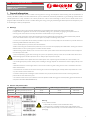
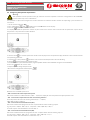
1. General information
GE556Y401 and GE556Y402 satellites enable metering thermal energy consumptions when heating and the production of
Sanitary Hot Water (SHW) in modern autonomous systems with heat centralized production (eg. teleheating). Control of the
satellite parameters is fully electronic. The various parameters can be entered through a remote device which works also as
programmable chronothermostat.
The satellites oer great energy saving by minimizing the ow request from the primary side
and reducing the delivery temperature.
1.1 Warnings
• Installation must be carried out by qualied personnel authorized by the building administration body.
Comply with the regulations in terms of use (installation, tting, etc...), operation, re-gauging and replacement of
metering units. Also refer to assembly instructions included with every metering unit.
• Risk of scalds and electric shocks. Only qualied personnel authorized by the building administration body should
access the satellite. Misuse may cause serious injuries to people and damage the system.
• An excessive temperature of the sanitary hot water may cause scalds to people; too cold water may lead to undesired
bacterial growth within the hot water system.
• Some satellite parts may overheat, do not touch them.
• Before connecting the satellite to the power line, make sure it has been properly lled with water. Starting the satellite
without water inside may damage the circulator and the satellite.
• When starting up the satellite, make sure no one uses the system water till the water temperature has been adjusted
in order to prevent scalds.
• To prevent polluting agents from entering the system, rst open the primary circuit valves and then the return valves
when starting up the satellite. Open the valves slowly to prevent pressure peaks.
• Do not cut o the electric power from the control panel. This may damage the circulator, the valve actuators, etc...
• The cleaning frequency of the sanitary water exchanger strongly depends on the hardness of the supply sanitary cold
water.
• With water hardness values higher than 15°f we recommend using anti-scaling devices to be selected based on the
water characteristics.
• To enhance the resistance to limestone crusting, we recommend adjusting the sanitary water temperature at a value
very close to the value of actual use.
• Clean the sanitary water exchanger at the end of the rst year; then, based on the limestone crusting status, this
period can be extended to two years.
• The satellite can be used in closed boiler rooms for operation with non-aggressive uids (water, glycol-based water in
compliance with VDI 2035/ÖNORM 5195).
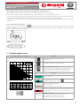
1.2 Versions and product codes
Code Type Heating side power SHW exchanger nominal power Template with valves
GE556Y401 Heating and SHW production 26 kW 58 kW GE551Y074
GE556Y402 Heating and SHW production 26 kW 67 kW GE551Y074
Warning.
• Every satellite includes:
- a label with the satellite model identication data;
- a label proving its compliance with electric and hydraulic tests;
• Every satellite is identied by a serial number both inside and on the
packaging.

2
0795EN January 2020
User and maintenance manUal
ElEctronic rEgulation satEllitEs
gE556Y401, gE556Y402
gE556-2 sEriEs
1.3 Completion codes
The components listed below may be installed on every satellite:
• Thermal energy metering unit series GE552
• Sanitary hot water metering unit series GE552-2
• Template with 6 interception valves and 3/4” connections: code GE551Y074
• Optional unit for sanitary cold water: code GE550Y001
1.4 Main characteristics
• SET POINT electronic thermoregulation to control SHW and heating temperatures.
• Remote control with chronothermostat function to control the parameters, with display.
• External temperature probe for climatic compensation.
• Heat exchanger for SHW instantaneous production.
• Control ow switch for SHW production priority.
• Motorized 3-way priority valve, on delivery of primary side.
• Motorized 2-way modulating valve, on return of primary side.
• Filter and manual air vent valve on the primary side.
• Low-pressure safety pressure switch on primary side.
• Thermal and electric safety valve on heating side.
• 3/4“M connections.
• 15/6 self-modulating circulator, 130 mm central distance, compliance with ErP (2009/125/CE).
• Heat exchanger and fully-insulated pipes.
• WRAS certied components for sanitary circuit.
• Spacer for metering unit installation.
• Varnished metal sheet cabinet (RAL9010) with key lock.
1.5 Technical data
• Max. working temperature: 90 °C
• Max. working pressure of primary circuit: 10 bar
• Max. working pressure of SHW secondary circuit: 10 bar
Warning.
Max. working dierential pressure for primary side = 4 bar (priority valve)
• Temperature range of heating secondary circuit: low temperature 25÷45 °C (factory original setting)
high temperature 25÷85 °C
• Temperature range of SHW secondary circuit: 30÷60 °C (SET POINT 50 °C)
• Primary nominal ow: 1070 l/h @ 75 °C for 58 kW
1150 l/h @ 75 °C for 67 kW
• Electric power: 230 V; 50-60 Hz
• Weight: ~25 kg

3
0795EN January 2020
User and maintenance manUal
ElEctronic rEgulation satEllitEs
gE556Y401, gE556Y402
gE556-2 sEriEs
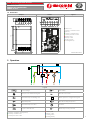
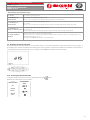
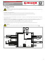
1.6 Dimensions
Template Satellite Legend
B
A
C
D
E
F
G
102450
721
169 94
105 60 60 60 60 60 45
450
390 3030
450
105 60 60 60 60 60 45
630
180
47
A B C ED F G
X
X: Cablecover
A: Sanitary cold water outlet
(optional)
B: Sanitary cold water inlet
C: Sanitary hot water outlet
D: Primary inlet
E: Primary outlet
F: Heating return
G: Heating delivery
Dimensions in mm
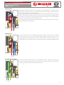
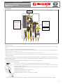
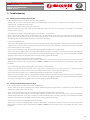
2. Operation
E
D
G
F
CB
F
P
E
W
Legend
Heat exchanger
FF
Flow switch
WW
Brass spacer for SHW metering unit Manual air vent valve
Motorized 2-way modulating valve
EE
Plastic spacer for energy metering unit
Temperature probe Motorized 3-way priority valve
Motorized 2-way zone valve Circulator
By-pass lockshield valve
PP
Minimum pressure pressostat
A: Sanitary cold water outlet (optional)
B: Sanitary cold water inlet
C: Sanitary hot water outlet
D: Primary inlet
E: Primary outlet
F: Heating return
G: Heating delivery

4
0795EN January 2020
User and maintenance manUal
ElEctronic rEgulation satEllitEs
gE556Y401, gE556Y402
gE556-2 sEriEs
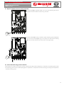
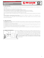
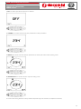
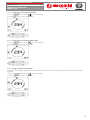
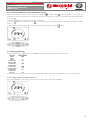
Primary circuit
E
D
Fig. 1
Inlet (D) and return (E). The primary circuit includes an inspectionable lter, a motorized 3-way
priority valve, a manual air vent valve, a heat exchanger, a pressure gauge, a minimum pressure
switch and a motorized 2-way modulating valve.
Energy-saving function: the 2-way modulating valve, controlled by the satellite electronic control,
limits to the minimum the ow request by the primary circuit to obtain the SET POINT preset
temperature. The priority valve diverts the ow into the heat exchanger (in case of SHW request:
SHW ow switch activated) or into the heating system.
The thermal energy metering unit can be installed in place of the plastic spacer by inserting its
temperature probe in the housing (1).
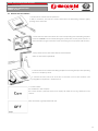
Heating circuit
E
D
G
F
Fig. 2
Delivery (G) and return (F). The heating circuit includes a motorized 2-way zone valve working
as thermal safety device (the valve interrupts the ow within the system when the delivery
temperature exceeds the temperature set on the remote control - SET POINT - by at least 5 °C),
an adjustable by-pass lockshield valve and a high energy eciency circulator (ErP 2009/125/CE).
Sanitary hot water circuit
Cold water inlet (B), hot water outlet (C) and cold water outlet (A - optional). The SHW circuit
includes a ow switch and a brass spacer to install the liter metering unit. A sanitary hot water
metering unit can be installed in place of the brass spacer.
B
C
A
Fig. 3

5
0795EN January 2020
User and maintenance manUal
ElEctronic rEgulation satEllitEs
gE556Y401, gE556Y402
gE556-2 sEriEs
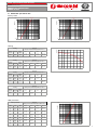
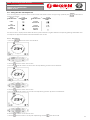
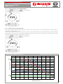
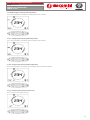
2.1 GE556Y401 operational data
Primary circuit
Primary circuit for SHW production, modulating valve fully open (see g.1)
1,00
0,10
0,01
0,1 1,0 10,0
Q [m
3
/h]
Δp [bar]
Kv = 2,08
Heating primary circuit, lockshield valve and modulanting valve both open (see g.2)
1,00
0,10
0,01
0,1 1,0 10,0
Q [m
3
/h]
Δp [bar]
Kv = 1,9
Heating
Heating
Flow [l/h]
Primary circuit outlet temperature (35-30 °C)
Circulator
speed
Flow [l/h]
Power
[kW]
75 °C 70 °C 65 °C 60 °C
Max 1500 8,8
170 l/h
(30 °C)
190 l/h
(30 °C)
215 l/h
(30 °C)
250 l/h
(30 °C)
Primary circuit data for delivery temperature 35-30 °C
Heating
Flow [l/h]
Primary circuit outlet temperature (45-40 °C)
Circulator
speed
Flow [l/h]
Power
[kW]
75 °C 70 °C 65 °C 60 °C
Max 1500 8,8
215 l/h
(40 °C)
250 l/h
(40 °C)
300 l/h
(40 °C)
375 l/h
(40 °C)
Primary circuit data for delivery temperature 45-40 °C
Heating
Flow [l/h]
Primary circuit outlet temperature (60-45 °C)
Circulator
speed
Flow [l/h]
Power
[kW]
75 °C 70 °C 65 °C 60 °C
Max 1500 26,3
750 l/h
(45 °C)
900 l/h
(45 °C)
1130 l/h
(45 °C)
-
Max 1200 21 - - -
1200 l/h
(45 °C)
Primary circuit data for delivery temperature 60-45 °C
Heating
Flow [l/h]
Primary circuit outlet temperature (70-55 °C)
Circulator
speed
Flow [l/h]
Power
[kW]
75 °C 70 °C 65 °C 60 °C
Max 1200 21
900 l/h
(55 °C)
1200 l/h
(55 °C)
- -
Primary circuit data for delivery temperature 70-55 °C
Heating circulator diagram - Circulator with constant Δp (see g.2)
0
0 200 400 600 800 1000 1200 1400 1600
1
2
3
4
5
6
7
∆p [m H
2
O]
Q [l/h]
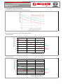
SHW production
Sanitary Hot Water
Flow [l/h]
Primary circuit outlet temperature (SHW 15-50 °C)
l/min l/h kW 75 °C 70 °C 65 °C 60 °C
12 720 29
495 l/h
(24 °C)
550 l/h
(24 °C)
665 l/h
(27 °C)
850 l/h
(30 °C)
15 900 37
630 l/h
(25 °C)
720 l/h
(26 °C)
850 l/h
(28 °C)
1050 l/h
(30 °C)
17 1020 41,5
730 l/h
(26 °C)
830 l/h
(27 °C)
1000 l/h
(29 °C)
1200 l/h
(30 °C)
20 1200 49
875 l/h
(27 °C)
1000 l/h
(28 °C)
1200 l/h
(30 °C)
1450 l/h
(31 °C)
22 1320 54
980 l/h
(28 °C)
1100 l/h
(28 °C)
- -
24 1440 58,8
1070 l/h
(28 °C)
1200 l/h
(28 °C)
- -
Primary circuit data for SHW production 15-50 °C
Hydraulic data for sanitary hot water circuits (sse g.3)
0,01
0,1 1,0 10,0
0,10
1,00
Δp [bar]
Q [m
3
/h]
Kv = 2,22

6
0795EN January 2020
User and maintenance manUal
ElEctronic rEgulation satEllitEs
gE556Y401, gE556Y402
gE556-2 sEriEs
2.2 GE556Y40 energy saving features
Low return temperatures of primary circuit when used for sanitary water
60 65 70 75
Primary delivery temp. [°C]
20
22
24
26
28
30
32
Primary return temp. [°C]
12 l/min
15 l/min
17 l/min
20 l/min
22-24 l/min
Reduced ows requested to the primary circuit, when heating
- High temperature:
60 65 70 75
Primary delivery temp. [°C]
600
700
800
900
1000
1100
1200
1300
Primary flow rate [l/h]
26 kW
∆T (60-45 °C)
Q=1500 l/h
21 kW
∆T (70-55 °C)
Q=1200 l/h
- Low temperature:
60 65 70 75
Primary delivery temp. [°C]
100
150
200
250
300
350
400
450
500
550
Primary flow rate [l/h]
9 kW
∆T (35-30 °C)
Q=1500 l/h
9 kW
∆T (45-40 °C)
Q=1500 l/h

7
0795EN January 2020
User and maintenance manUal
ElEctronic rEgulation satEllitEs
gE556Y401, gE556Y402
gE556-2 sEriEs
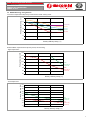
2.3 GE556Y402 operational data
Primary circuit
Primary circuit for SHW production, modulating valve fully open (see g.1)
1,00
0,10
0,01
0,1 1,0 10,0
Q [m
3
/h]
Δp [bar]
Kv = 2,13
Heating primary circuit, lockshield valve and modulating valve fully open (see g.2)
1,00
0,10
0,01
0,1 1,0 10,0
Q [m
3
/h]
Δp [bar]
Kv = 1,9
Heating
Heating
Flow [l/h]
Primary circuit outlet temperature (35-30 °C)
Circulator
speed
Flow [l/h]
Power
[kW]
75 °C 70 °C 65 °C 60 °C
Max 1500 8,8
170 l/h
(30 °C)
190 l/h
(30 °C)
215 l/h
(30 °C)
250 l/h
(30 °C)
Primary circuit data for delivery temperature 35-30 °C
Heating
Flow [l/h]
Primary circuit outlet temperature (45-40 °C)
Circulator
speed
Flow [l/h]
Power
[kW]
75 °C 70 °C 65 °C 60 °C
Max 1500 8,8
215 l/h
(40 °C)
250 l/h
(40 °C)
300 l/h
(40 °C)
375 l/h
(40 °C)
Primary circuit data for delivery temperature 45-40 °C
Heating
Flow [l/h]
Primary circuit outlet temperature (60-45 °C)
Circulator
speed
Flow [l/h]
Power
[kW]
75 °C 70 °C 65 °C 60 °C
Max 1500 26,3
750 l/h
(45 °C)
900 l/h
(45 °C)
1130 l/h
(45 °C)
-
Max 1200 21 - - -
1200 l/h
(45 °C)
Primary circuit data for delivery temperature 60-45 °C
Heating
Flow [l/h]
Primary circuit outlet temperature (70-55 °C)
Circulator
speed
Flow [l/h]
Power
[kW]
75 °C 70 °C 65 °C 60 °C
Max 1200 21
900 l/h
(55 °C)
1200 l/h
(55 °C)
- -
Primary circuit data for delivery temperature 70-55 °C
Heating circulator diagram - Circulator with constant Δp (see g.2)
0
0 200 400 600 800 1000 1200 1400 1600
1
2
3
4
5
6
7
∆p [m H
2
O]
Q [l/h]
SHW production
Sanitary Hot Water
Flow [l/h]
Primary circuit outlet temperature (SHW 10-50 °C)
l/min l/h kW 75 °C 70 °C 65 °C
12 720 33,5
510 l/h
(18,5 °C)
580 l/h
(20 °C)
670 l/h
(22 °C)
15 900 42
660 l/h
(20,5 °C)
750 l/h
(22 °C)
880 l/h
(24 °C)
17 1020 47,5
770 l/h
(22 °C)
880 l/h
(23,5 °C)
1020 l/h
(25 °C)
20 1200 56
940 l/h
(23,5 °C)
1050 l/h
(24,2 °C)
-
22 1320 61,5
1040 l/h
(24 °C)
1160 l/h
(24,6 °C)
-
24 1440 67
1150 l/h
(25 °C)
1280 l/h
(25 °C)
-
Primary circuit data for SHW production10-50 °C
Hydraulic data for sanitary hot water circuits (see g.3)
0,01
0,1 1,0 10,0
0,10
1,00
Δp [bar]
Q [m
3
/h]
Kv = 2,32

8
0795EN January 2020
User and maintenance manUal
ElEctronic rEgulation satEllitEs
gE556Y401, gE556Y402
gE556-2 sEriEs
2.4 GE556Y402 energy-saving features
Low return temperatures of primary circuit when heating
Primary return temp. [°C]
Primary delivery temp. [°C]
Flows requested to the primary circuit reduced when heating
- High temperature:
60 65 70 75
Primary delivery temp. [°C]
600
700
800
900
1000
1100
1200
1300
Primary flow rate [l/h]
26 kW
∆T (60-45 °C)
Q=1500 l/h
21 kW
∆T (70-55 °C)
Q=1200 l/h
- Low temperature:
60 65 70 75
Primary delivery temp. [°C]
100
150
200
250
300
350
400
450
500
550
Primary flow rate [l/h]
9 kW
∆T (35-30 °C)
Q=1500 l/h
9 kW
∆T (45-40 °C)
Q=1500 l/h

9
0795EN January 2020
User and maintenance manUal
ElEctronic rEgulation satEllitEs
gE556Y401, gE556Y402
gE556-2 sEriEs
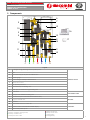
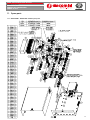
3. Components
ED
B
CA
5
10
3
11
2
1
4
15
7
6
12
8
13
9
14
G
F
16
17
Legend
1 Housing for energy metering unit temperature probe
PRIMARY CIRCUIT
2 Filter
3 Motorized 3-way priority valve for SHW function
4 Pressure gauge
5 Heat exchanger, sanitary hot water function
6 Manual air vent valve
7 Min. pressure pressostat
8 Motorized 2-way modulating valve
9
Plastic spacer for thermal energy metering unit
10
Flow switch
SHW PRODUCTION
11 Brass spacer for SHW liter metering unit
12 Motorized 2-way zone valve for thermal and electric safety
HEATING13 By-pass lockshield valve
14 Circulator
15 Cabinet with electronic control unit
CONTROLS16 Remote control / chronothermostat with display
17 External temperature probe
A: Sanitary cold water outlet (optional)
B: Sanitary cold water inlet
C: Sanitary hot water outlet
D: Primary circuit inlet
E: Primary circuit outlet
F: Heating return
G: Heating delivery

10
0795EN January 2020
User and maintenance manUal
ElEctronic rEgulation satEllitEs
gE556Y401, gE556Y402
gE556-2 sEriEs
4. Installation
4.1 Unpacking
• Remove the shipping packing, make sure the product is not damaged and that delivery has been carried out according to the
agreed terms and conditions.
• When handling the satellite, the pipes and the exchanger should not be exposed to stress. Do not move the satellite holding it
by the exchanger or pipes
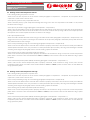
4.2 Installation set up
• Make sure the primary circuit complies with the rules in force. The available dierential pressure must be included between a
minimum of 0,5 bar and a maximum of 4 bar. In case of higher pressure values, install a dierential pressure controller.
• Wash the heating and sanitary hot water circuit.
4.3 Hydraulic system precautions
• Max. working temperature: 90 °C
• Primary circuit max. working pressure: 10 bar
• SHW secondary circuit max. working pressure: 10 bar
Warning.
Max. working dierential pressure for primary side = 4 bar (priority valve)
4.4 Electric system precautions
• Make sure the power voltage is 230 V and that the electric system features proper grounding.
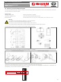
4.5 Template and satellite installation
Warning.
Hydraulic connection of heating, sanitary water and primary circuits should be carried out by qualied personnel and in
compliance with the local or national rules and provisions in force.
We recommend installing a check valve on the sanitary water circuit inlet.
Install the GE551Y074 template on a wall using screw anchors suitable for the type
of wall and equipment weight.
The satellite can be installed at any height however we recommend a distance of
1500÷1800 mm from the floor to the bottom edge of the satellite cover.
Install the ball valves in the template holes and lock the washers using a wrench.
Connect the system pipes to the ball valves with the template 3/4’’M connections
using proper adapters. For a correct installation of the pipes refer to the instructions
on the template label.
390 mm
450 mm

11
0795EN January 2020
User and maintenance manUal
ElEctronic rEgulation satEllitEs
gE556Y401, gE556Y402
gE556-2 sEriEs
Fit the GE556Y401/402 satellite in the corresponding threaded pegs of the template
and lock it using the included washers and nuts.
Before connecting the satellite to the template remove the
lock nuts from the threaded connections and then insert
the washers between the satellite connections and the template
valve caps.
MAX. 35 Nm
Tighten the template valve caps using a 35 Nm max. torque.

12
0795EN January 2020
User and maintenance manUal
ElEctronic rEgulation satEllitEs
gE556Y401, gE556Y402
gE556-2 sEriEs
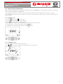
4.6 Start-up
ED
B
CA
G
F
1
Manually open the two-way
and three-way valves, forcing
the white indicator of the
actuator downwards.
ATTENTION
At the end of lling,
reactivate the automatic
operation of the actuator by
removing it and repositioning
it on the valve.
3
Remove the R473 actuator
from the valve body.
ATTENTION
At the end of lling,
reconnect the R473 actuator
to the valve body.
2
Make sure the lockshield is in
the fully open position.
4
Manual air vent valve
• Open the heating circuit 2-way valve and the diverter 3-way valve by forcing them, manually pushing the actuator white indicator
downwards (ref. 1).
• Make sure the heating circuit lockshield valve is completely open and remove the R473 thermoelectric head from the valve body
(ref. 2, 3).
• Open the sanitary cold water inlet (ref. B) to ll the sanitary water circuit.
• Open the primary circuit inlet (ref. D) to ll the primary and heating circuit then make sure the pressure on the satellite pressure
gauge is the same of the system pressure.
• When lling the system, open the manual air vent valve till water starts to come out (ref. 4).
• Keep the satellite pressurized and check visually for possible leakages in the various joints and glued parts as well as under the
exchanger insulation.
• Retighten all connections, including those originally tightened in factory. Should the connection require tightening after starting
up the satellite, decrease the system pressure before performing this operation. The washers may be damaged if the system
pressure is not reduced.
• ATTENTION: once the system has been lled, reactivate the actuators automatic operation.
To restore the automatic operation:
a. Disconnect the Molex electric connector from the actuator so as to ease its rotation.
b. The actuator is connected to the valve body, to remove it lift the locking mechanism directly under the
manual opening lever (ref. 1).
c. Push the actuator with your hand, without forcing it, towards the valve body while turning it in anticlockwise
direction by 1/8 turn (45°) .
d. Remove the actuator from the valve body.
e. Reinstall the actuator in reverse order.
f. Reconnect the Molex electric connector to the actuator.
• Complete the start-up procedure by connecting the L and N terminals of the satellite electronic card to the power supply.

13
0795EN January 2020
User and maintenance manUal
ElEctronic rEgulation satEllitEs
gE556Y401, gE556Y402
gE556-2 sEriEs
4.7 Optional: additional unit for sanitary cold water
Install the GE500Y254 additional ball valve in the corresponding hole of the
template and lock it with the washer using a wrench.
MAX. 35 Nm
B
A
MAX. 35 Nm
Install the GE550Y001 sanitary cold water outlet unit tting it to the additional
valve previously installed (A) using a max. torque of 35 Nm and to the tting
(B) on the sanitary cold water inlet unit, after removing the plug.
4.8 Flow and thermal energy meter installation
Flow and thermal energy metering units must be installed according to the manufacturer’s instructions and replacing them at the
corresponding spacers on the satellite (paragraph 3 “Components” - component 9 for thermal energy metering unit; components
11 for ow metering units).

14
0795EN January 2020
User and maintenance manUal
ElEctronic rEgulation satEllitEs
gE556Y401, gE556Y402
gE556-2 sEriEs
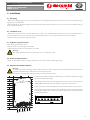
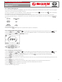
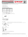
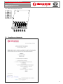
4.9 Positioning of external temperature probe
The external temperature probe includes a PCB inside a plastic body; both the temperature-sensitive element and the connection
terminal board are welded to the PCB.
Technical data
Housing material: ABS Working temperature: -40÷60 °C
Dimensions: 60x45x32 mm Electric connection: M3 threaded terminals
Protection: IP44 Provided accessories: N° 2 5x25 mm screw anchors; N° 2 3,5x25 mm screws
Warning.
• The probe has no repairable parts. Repairing is not contemplated.
• The device must be connected with electric power o.
• The device must be connected in compliance with the rules in force.
• Use connection wires with proper insulation, working temperature and humidity resistance.
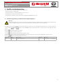
The temperature probe must be installed on an external wall of the building.
The probe can be installed in two dierent positions: horizontally or vertically.
Horizontal installation diagram Vertical installation diagram
Important: the temperature to be measured must not be directly aected by external agents.
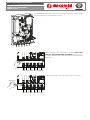
Connect the external temperature probe to terminals 27-28 of the electronic card (paragraph 3 “Components” - components 15)
with a 0,6 mm
2
wire. The wire maximum length must be 50 m.
24 23 22 21 20 19
32 31 30 29 28 27 26 25
40 39 38 37 36 35 34 3342 41
1 2 3 4 5 6 7 8
9 10 11 12 13
14 15
L N
18
17
16
CHIUDE - MARRONE
COMUNE - BLU
APRE - NERO
TENSIONE 230 Vac
CHIUDE - MARRONE
COMUNE - BLU
APRE - NERO
LINEA - MARRONE
NEUTRO - BLU
TERRA - GIALLO
ROSSO
BIANCO
VERDE
GRIGIO
NERO
LINEA - MARRONE
NEUTRO - BLU
FLUSSOSTATO
TESTA
R473M
230 VAC
PRESSOSTATO
SONDA SANITARIO
SONDA MANDATA
MISCELATRICE
CIRCOLATORE
DEVIATRICE
SONDA RITORNO
COMANDO REMOTO K480Y002
SONDA ESTERNA K365P
TERMOSTATO DI SICUREZZA K373

15
0795EN January 2020
User and maintenance manUal
ElEctronic rEgulation satEllitEs
gE556Y401, gE556Y402
gE556-2 sEriEs
5. Satellite standard presetting
The satellite is provided with the following conguration:
• Sanitary hot water set point: 50 °C
• Heating set point: 45 °C (low temperature range 25÷45 °C)
• Heating by-pass lockshield valve: fully open
• Compensation coecient of KD external thermoregulation (P04 parameter): 30
5.1 Parameter programming: variation from low to high temperature
Warning.
Parameter programming must be carried out by qualied personnel authorized by the building administration body.
Improper programming may lead to satellite mulfunctions and damage the system components.
The heating set point range may be modied from low temperature (25÷45 °C) to high temperature (25÷85 °C) by pressing at the
same time the
and buttons of the K480Y002 remote control for at least 5 seconds till the TSP text appears on the
display.
Turn the knob to T01 parameter number.
Turn the knob to select the parameter.
Turn the knob to change the heating temperature range.
Turn the knob to select the heating temperature range (presetting: 01 = reduced; low temperature range 25÷45 °C).
Press the button to go back to the initial screen.
Parameter Range Description Default Selections
T01 00 ÷ 01 Range riscaldamento 1 00 = normal 01 = reduced

16
0795EN January 2020
User and maintenance manUal
ElEctronic rEgulation satEllitEs
gE556Y401, gE556Y402
gE556-2 sEriEs
6. Remote control/chronothermostat with display, K480Y002
Warning.
Before connection, make sure the satellite is set up for the K480Y002 remote control by referring to the corresponding
instructions.
6.1 Technical characteristics
• Power: by means of communication bus
• Number of temperature levels: 2 (DAYTIME / NIGHT TIME)
• Temperature setting range DAYTIME: 5÷30 °C
• Temperature setting range NIGHT TIME: 5÷30 °C
• Temperature setting range MANUAL: 5÷30 °C
• Setting range for intervention thermal dierential (OFF): 0,0÷1,0 °C
• Setting range for intervention thermal dierential (ON); -1,0÷ -0,1 °C
• Correct operation range for room temperature probe: -40÷50 °C
• Setting range for low temperature heating: 25÷45 °C
• Setting range for high temperature heating: 25÷85 °C
• Setting range for sanitary hot water temperature: 30÷60 °C
• Temperature resolution: 0,1 °C
• Temperature setting range for activation of room anti-freezing function: 0,1÷10,0 °C
• Limit temperature for deactivation of room anti-freezing function: setup value +0,6 °C
• Timer programmer resolution: 30 minutes
• Max. number of daily activations and deactivations: 48
• Number of standard heating programs: 1
• Clock updating time in case of blackout: 1 h
• Operational temperature range: 0÷50 °C
• Stocking room temperature: -10÷50 °C
• Dimensions (L×H×W): 118×85×30 mm
• Max. length of satellite connection wire: 50 m
• Satellite connection wire section: 0,5÷1,5 mm²
6.2 Buttons and display
A Selection of operational status
B Time and temperature setting
C
Weekly programming
D
Modication of displayed (rotate) –
Automatic/manual selection (press)
E
Alarm reset
F
Selection of temperature level
(daytime/night time)
G
Temperature displaying

17
0795EN January 2020
User and maintenance manUal
ElEctronic rEgulation satEllitEs
gE556Y401, gE556Y402
gE556-2 sEriEs
6.3 LCD display symbols
Icon Fixed Blinking
Current temperature Anomaly code
Time/temperature
Current day of the week Day of the week modication
Sanitary water enabled Sanitary water request in progress
Heating enabled Heating request in progress
Manual operation mode
Heating program Heating program modication
Current room set point Provisional modication of room set point
External temperature
System pressure
Time and day of the week set up
Daytime temperature set up
Night time temperature set up
Heating temperature Heating temperature set up
Sanitary water temperature Sanitary water temperature set up
Kd value set up
Current temperature level = daytime
Current temperature level = night time
Anomaly with no restarting attempts left Anomaly with restarting attempts available
Anomaly with service request
Nigh time level
Daytime level

18
0795EN January 2020
User and maintenance manUal
ElEctronic rEgulation satEllitEs
gE556Y401, gE556Y402
gE556-2 sEriEs
6.4 General warnings
• Read the warnings included in these instructions thoroughly as they provide important information on use, installation and
service safety.
• The system installation must comply to the safety rules in force.
• When unpacking the device, make sure it is not damaged before installation.
• The device should be used only for its specic purpose: any other use must be considered improper.
• Service of the device must be carried out by a qualied support center authorized by the manufacturer.
• Failure to comply with the above warnings may compromise the device safety.
• When installed to control a low temperature zone, a low temperature safety thermostat should be installed on the controlled
zone.
• The manufacturer is not liable for possible damages deriving from malfunctions, exceptional events, conguration errors,
improper, erroneous and unreasonable use of the device.
• The manufacturer reserves the right to carry out modications and any other operation deemed necessary for constant
improvement of the product.
6.5 Main characteristics
The K480Y002 remote control has been designed to oer ideal temperature conditions at any time of the day, enabling to perform
any satellite setting remotely.
The K480Y002 remote control can be easily programmed: a wide LCD display makes this operation extremely easy at any time and
the user can both verify and change the settings.
The K480Y002 remote control is electrically connected to the satellite by two unpolarized conductors through which it receives
the required power to function and put the two devices in communication.
It can function with the memorized standard program right after installation. The program can be modied according to the user’s
needs.
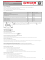
6.6 Remote control positioning
The K480Y002 remote control must be installed by qualied personnel. For
proper installation, set up a dedicated power line to connect the remote control
according to the rules in force for electric systems. Should this be unfeasible,
possible interference by other electric wires may cause mulfunctions to the
remote control. Install the K480Y002 remote control at a height of about 1,5 m
in a position suitable to read the room temperature correctly. Do not install in
niches, behind doors or curtains, near heating sources, under direct sun light
or water sprays.
La pagina si sta caricando...
La pagina si sta caricando...
La pagina si sta caricando...
La pagina si sta caricando...
La pagina si sta caricando...
La pagina si sta caricando...
La pagina si sta caricando...
La pagina si sta caricando...
La pagina si sta caricando...
La pagina si sta caricando...
La pagina si sta caricando...
La pagina si sta caricando...
La pagina si sta caricando...
La pagina si sta caricando...
La pagina si sta caricando...
La pagina si sta caricando...
La pagina si sta caricando...
La pagina si sta caricando...
La pagina si sta caricando...
La pagina si sta caricando...
La pagina si sta caricando...
La pagina si sta caricando...
-
 1
1
-
 2
2
-
 3
3
-
 4
4
-
 5
5
-
 6
6
-
 7
7
-
 8
8
-
 9
9
-
 10
10
-
 11
11
-
 12
12
-
 13
13
-
 14
14
-
 15
15
-
 16
16
-
 17
17
-
 18
18
-
 19
19
-
 20
20
-
 21
21
-
 22
22
-
 23
23
-
 24
24
-
 25
25
-
 26
26
-
 27
27
-
 28
28
-
 29
29
-
 30
30
-
 31
31
-
 32
32
-
 33
33
-
 34
34
-
 35
35
-
 36
36
-
 37
37
-
 38
38
-
 39
39
-
 40
40
-
 41
41
-
 42
42


Giacomini GE556-2 Series User And Maintenance Manual
- Tipo
- User And Maintenance Manual
in altre lingue
- English: Giacomini GE556-2 Series
Documenti correlati
-
Giacomini R453 Istruzioni per l'uso
-
-
-
-
-
-
-
-
-
Altri documenti
-
BLACK DECKER BXCSH1200E Convector Manuale utente
-
 Olimpia Splendid SHERPA 4 Guida d'installazione
-
La Nordica TERMOSUPREMA COMPACT DSA Instructions For Installation, Use And Maintenance Manual
-
-
Olimpia Splendid Sherpa AQUADUE OS-CETNH48EI Manuale del proprietario
-
Nordica TermoSovrana DSA Instructions For Installation, Use And Maintenance Manual
-
LK Armatur SmartComfort LK 130 Manuale utente
-
ACV Control Unit THETA Istruzioni per l'uso
-
Sime Murelle Equipe 100 150 Box ErP Manuale del proprietario
-
