ARX Racing ARM-540 PK Manuale utente
- Categoria
- Giocattoli telecomandati
- Tipo
- Manuale utente

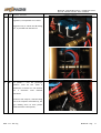
M
ANUALE DI
A
SSEMBLAGGIO
AR
X
-540
2007-1.0 – ITA Introduct ion / Pag.
Garanzia
AR Racing garantisce che il prodotto è esente da difetti. Il valore garantito non eccede comunque il costo di acquisto del
prodotto. La garanzia non copre qualunque danno provocato dopo l’acquisto dal danneggiamento delle singole
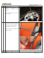
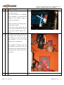
componenti o modifiche. La segnalazione di eventuali componenti mancanti/difettosi deve essere prontamente
segnalata, e comunque entro 7 giorni dalla data di acquisto. In caso di componenti difettosi, è necessario mostrare alla
AR Racing il componente difettoso. Le componenti eventualmente mancanti/difettose verranno inviate sol o dimostrando
di avere acquistato il prodotto. In caso di componenti mancanti/difettose segnalate il problema al punto d’acquisto
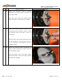
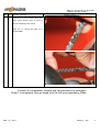
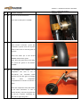
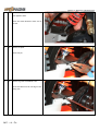
dove è stato acquistato il prodotto, oppure direttamente alla AR Racing se acquistato via Internet dal sito della AR
Racing, inviando una mail all’indirizzo info@armodelling.com.
Manuale di
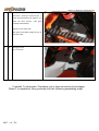
Manuale di Manuale di
Manuale di
Assemblaggio
AssemblaggioAssemblaggio
Assemblaggio
ARX
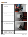
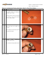
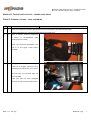
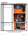
ARXARX
ARX-
--
-540
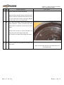
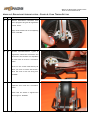
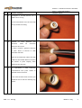
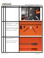
540540
540 PK
PK PK
PK
ARM
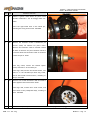
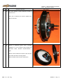
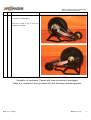
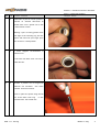
ARM ARM
ARM –
––
– 540
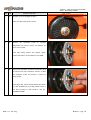
540 540
540 PK
PK PK
PK

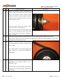
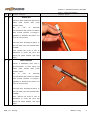
M
ANUALE DI
A
SSEMBLAGGIO
AR
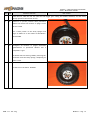
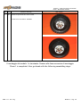
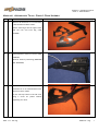
X
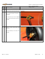
-540
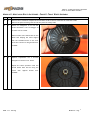
2007-1.0 – ITA Introduct ion / Pag.
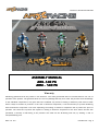
Introduzione
Grazie per aver acquistato il model kit ARx-540. La AR Racing lavora per sviluppare modelli in scala
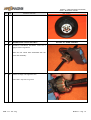
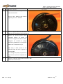
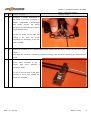
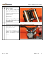
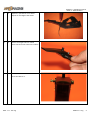
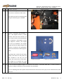
di elevata qualità frutto di ricerche volte a realizzare prodotti innovativi.
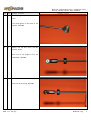
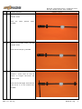
Il Manuale Istruzioni contiene tutti gli elementi necessari a preparare il modello per la messa in
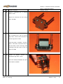
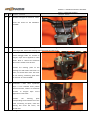
strada. AR Racing vi prega di seguire con attenzione le Istruzioni e di familiarizzare con il prodotto
una volta assemblato e completato con le componenti di alimentazione prima di un pieno utilizzo.
Riteniamo possibile che siano necessarie alcune ore di pratica prima di poter trarre il massimo
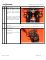
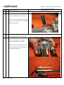
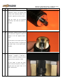
divertimento dal prodotto acquistato.
NOTA BENE: in questo manuale sono contenute sia le istruzioni del modello CROSS che MOTARD.
LE immagini prevalenti sono quelle del modello cross.
Le differenti fasi di montaggio tra i due modelli sono evidenziate all’inizio del commento delle
fotografie.
Componenti necessari per il montaggio e l’uso
Utensili necessari al montaggio
4 chiavi a brugola di ottima qualità nelle
misure 3.0mm, 2.5mm, 2.0mm, 1.5mm
1 chiave a bussola per esagono da 7mm
1 cacciavite Philips (piccolo)
1 pinza a becchi sottili
1 taglierino
1 frenafiletti tipo medio
colla cianoacrilica
1 righello
Dispositivi di Protezione Individuale
anti-infortunistica
Guanti protettivi
Componenti - non incluse – necessarie al funzionamento del modello
Radiocomando
Batteria
Motore

M
ANUALE DI
A
SSEMBLAGGIO
AR
X
-540
2007-1.0 – ITA Introduct ion / Pag.
Regolatore
Altri elementi utili
Olio
Importante: Leggere con attenzione quanto segue prima di
iniziare l’assemblaggio
1. Warning: Questo prodotto non è un giocattolo.
Questo prodotto non è destinato a persone minori di 16 anni.
Questo prodotto può essere utilizzato da persone minori di 18 anni solo se assistiti da un
adulto responsabile.
Tenere il prodotto e tutte i relativi componenti a distanza di sicurezza da bambini minori di
3 anni!!! Le componenti distaccabili del prodotto possono essere ingerite dai bambini minori
di 3 anni!!! Rischio di soffocamento!!!
Uso specifico del prodotto: Auto o Moto radiocomandata.
Importante: in caso di clima freddo (al di sotto di 5°C) è possibile che alcune componenti del
Modello diventino più fragili e possano rompersi utilizzando il Modello. In caso di utlizzo in
presenza di tali temperature, evitare al massimo possibili collisioni del modello con ostacoli.
2. Questo è un modello di elevate performance. Si consiglia di familiarizzare con l’uso del modello,
seguendo il manuale e le sue fasi di costruzione prima di un suo pieno utilizzo.
3. Non utilizzate questo prodotto dove vietato, su strade pubbliche, in caso di pioggia, nei posti
affollati, vicino ad un aeroporto ed in qualunque area dove è vietato l’uso di radio-modelli.
4. Quando utilizzato con il vostro radiocomando, controllate se sono presenti divieti di utilizzo di
radio frequenze nell’area in cui operate e/o se altri modellisti stanno utilizzando la stessa radio
frequenza.
5. L’utilizzo improprio del prodotto può provocare danni a cose o persone. AR Racing ed i suoi
distributori non hanno responsabilità per danni risultanti dalla spedizione, dall’errato montaggio
o da un uso improprio.
6. AR Racing non si assume e non accetta alcuna responsabilità per danni a cose o persone
derivanti dall’utilizzo di materiali non indicati, o da un uso non conforme alle istruzioni. Dal
momento in cui l’acquirente inizia le attività di assemblaggio, egli si assume le responsabilità
derivanti dall’utilizzo/montaggio improprio.

M
ANUALE DI
A
SSEMBLAGGIO
AR
X
-540
2007-1.0 – ITA Introduct ion / Pag.
7. AR Racing consiglia di seguire attentamente le istruzioni ed estrarre i singoli componenti dai
sacchetti numerati in base alla fase di montaggio. Quando non indicato diversamente, lasciare i
singoli componenti nei sacchetti per evitare di perderli o confonderli nella fase di montaggio. I
componenti sono presenti in numero esatto per completare il montaggio, ad eccezione di un
sacchetto con alcune viti di ricambio.
8. Non osservare scrupolosamente le istruzioni può compromettere il montaggio e danneggiare i
componenti.
9. La mancata applicazione del frenafiletti quando consigliato potrebbe comportare l'allentamento
delle viti.
10. Un serraggio eccessivo delle viti, superiore rispetto a quanto indicato nelle Istruzioni di
Assemblaggio può determinare la deformazione/rottura del pezzo.
11. A causa dell'elevato numero delle parti in movimento, prima di raggiungere la migliore
funzionalità/scorrevolezza è necessario un periodo di rodaggio (4/6 batterie).
12. I materiali degli ingrannaggi sono autolubrificanti e non richiedono l'applicazione di grasso. Un
eventuale utilizzo di grasso è lasciato alla discrezione dell'utilizzatore.
13. Alcune componenti possono richiedere un ulteriore lieve lavorazione manuale per raggiungere il
perfetto assemblaggio.
14. Capita che a volte siano raffigurate gomme motard durante il montaggio del modello cross e
vice versa. Dato che ciò non impedisce la corretta comprensione del testo non è prevista una
revisione in tal senso. Ove le differenze tra i modelli sono sostanziali vengono utilizzate le foto
corrette.
Elenco Moduli Assemblaggio
Il montaggio del prodotto ARX-540 si basa su un dettagliato manuale di Istruzioni composto da 9 fasi
o Moduli di assemblaggio, basati sull’utilizzo della lista dei componenti che compongo il Kit, riuniti
logicamente in 49 sacchetti di seguito elencati:
Elenco Moduli
Modulo 1: Ruota Posteriore

M
ANUALE DI
A
SSEMBLAGGIO
AR
X
-540
2007-1.0 – ITA Introduct ion / Pag.
Modulo 2: Ruota Anteriore
Modulo 3: Retrotreno
Modulo 4: Regolazione tensione catena
Modulo 5: Forcelle Anteriori
Modulo 6 : Telaio
Modulo 7: Ammortizzatore
Modulo 8: Assemblaggio finale
Modulo 9: Messa in strada
La pagina sta caricando ...
La pagina sta caricando ...
La pagina sta caricando ...
La pagina sta caricando ...
La pagina sta caricando ...

M
ODULO
1
-
M
ONTAGGIO
R
UOTA
P
OSTERIORE
P
HASE
1
R
EAR
W
HEEL
A
SSEMBLY
2008 – 2.0 – ITA - Eng Modulo 1 / Pag.
1
M
ODULO
1
-
M
ONTAGGIO
R
UOTA
P
OSTERIORE
-
P
HASE
1
–
R
EAR
W
HEEL
A
SSEMBLING
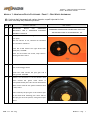
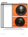
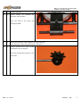
NB: Il colore degli ingranaggi può variare rispetto a quelli riportati in foto.
NB: Gear color may vary from the pictures.
Mod num Istruzione – Instrucion Foto - Picture
1. 1. MONTAGGIO RUOTA CON GIROSCOPIO
MECCANICO. PER IL GIROSCOPIO ELETTRICO
ANDARE AL PUNTO 56
ASSEMBLING INSTRUCTIONS FOR MECHANIC GYRO FOR
THE ELECTRIC GYRO GO TO INSTRUCION 1. 56.
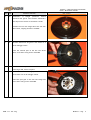
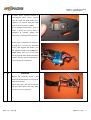
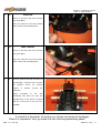
1. 2. Estrarre dal sacchetto X002 il guscio ruota destro
(con pioli)
NB: non estrarre le viti, lasciarle nel sacchetto
per successivo utilizzo!!!!
From box X-002 extract the right wheel shell
(with pins). PICTURE
Note: do not extract the screws, keep them in
the bag for future use!!!
1. 3. Estrarre dal sacchetto X031 la corona dentata e
le 6 viti di fissaggio.FOTO
From box X-031 extract the spur gear and 6
fixing screws. PICTURE
1. 4. Inserire con attenzione la corona dentata nella
parte interna del guscio ruota destro in
corrispondenza dei pioli. NB: verso di inserimento
della corona come da foto (parte scanalata verso
l’alto). FOTO
Insert carefully the spur gear in the internal part
of the wheel shell matching pins. Note: side of
the spur gear as in the picture, with grooved part
above.

M
ODULO
1
-
M
ONTAGGIO
R
UOTA
P
OSTERIORE
P
HASE
1
R
EAR
W
HEEL
A
SSEMBLY
2008 – 2.0 – ITA - Eng Modulo 1 / Pag.
2
Mod num Istruzione – Instrucion Foto - Picture
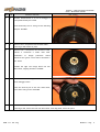
1. 5. Avvitare delicatamente le 6 visti di fissaggio in
corrispondenza dei pioli. FOTO
Screw delicately the six fixing screws matching
the pins. PICTURE
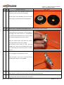
1. 6. Estrarre tutti i componenti dal sacchetto X004
From bag X-004 extract all parts.
1. 7. Estrarre tutti i componenti dal sacchetto X-003,
inserire il cuscinetto a fondo nella sede.
Posizionare la flangia posteriore destra
all'esterno del guscio ruota destro allineando i
fori. FOTO
Position the right rear flange above the rear
wheel shell, aligning the holes. PICTURE
1. 8. Avvitare dall'interno del guscio ruota destro le 6
viti di fissaggio. FOTO
From the internal part of the rear wheel shell,
screw the 6 fixing screws. PICTURE
1. 9. Estrarre dal sacchetto X002 il guscio ruota sinistro. Estrarre tutti i componenti dal sacchetto X004.
From bag X-002, extract the left rear wheel shell. From bag X004, extract all parts.

M
ODULO
1
-
M
ONTAGGIO
R
UOTA
P
OSTERIORE
P
HASE
1
R
EAR
W
HEEL
A
SSEMBLY
2008 – 2.0 – ITA - Eng Modulo 1 / Pag.
3
Mod num Istruzione – Instrucion Foto - Picture
1. 10. Posizionare la flangia posteriore sinistra
all'esterno del guscio ruota sinistro allineando i
fori dopo avervi inserito il cuscinetto a fondo.
Position the left rear flange above the left rear
wheel shell, aligning the holes. PICTURE
1. 11. Avvitare dall'interno del guscio ruota sinistro le 6
viti di fissaggio. FOTO
From the internal part of the left rear wheel
shell, screw the 6 fixing screws. PICTURE
1. 12. Estrarre tutti i componenti dal sacchetto X005
From bag X-005, extract all parts
1. 13. Inserire la corona nella flangia posteriore sinistra
ed avvitare le 6 viti di fissaggio. FOTO.
Insert the spur gear in the rear left flange and
screw the 6 fixing screws. PICTURE.

M
ODULO
1
-
M
ONTAGGIO
R
UOTA
P
OSTERIORE
P
HASE
1
R
EAR
W
HEEL
A
SSEMBLY
2008 – 2.0 – ITA - Eng Modulo 1 / Pag.
4
Mod num Istruzione – Instrucion Foto - Picture
1. 14. Mettete da parte i due semigusci posteriori per
passare alla fase successiva di montaggio.
At this stage of the assembling of the rear wheel
shell, please go ahead with the following steps
1. 15. Estrarre tutti i componenti dal sacchetto X-032 - From bag X-032, extract all parts
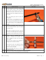
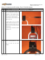
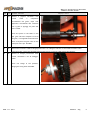
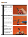
1. 16. Bloccare gli alberi portasatelliti con le viti, una
volta applicatovi il frenafiletti, come da FOTO. Il
bloccaggio deve essere deciso e il portasatelliti
va tenuto fermo solamente con le mani (evitare
di rovinare la superficie con pinze o altro).
Block the satellite gear shaft with the screws,
once applied the thread lock. PICTURE.
This blocking action must be firm, and the
satellite gear shaft must be handled with hands
to avoid ruining the surface with pliers or other
objects.
1. 17. Avvitare di un paio di giri il grano nell'apposito
foro di fissaggio nel portasatelliti. FOTO
Screw the grain, only a bit, in the hole on the
satellite gear shaft as in the PICTURE
1. 18. Mettete da parte il gruppo portasatelliti per passare alla fase successiva di montaggio.
Keep aside the satellite gear shaft and go ahead with the following steps.
1. 19. Estrarre dal sacchetto X-034 il perno ruota, un seger.
From bag X-034, extract the wheel pin, and a seger.

M
ODULO
1
-
M
ONTAGGIO
R
UOTA
P
OSTERIORE
P
HASE
1
R
EAR
W
HEEL
A
SSEMBLY
2008 – 2.0 – ITA - Eng Modulo 1 / Pag.
5
Mod num Istruzione – Instrucion Foto - Picture
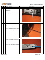
1. 20. Per questa operazione è necessario l'utilizzo degli
occhiali protettivi: inserire il seger nell'apposita
cava del perno ruota adiacente al piano fresato
aiutandosi con la pinza. Verificare che tutti e tre
i nasetti del seger siano alloggiati all'interno della
cava. FOTO
Note: the following step must be done used
safety glasses.
Insert the seger in the predisposed way on the
wheel pin, close to the milled flat part, using the
pliers. Verify that all the three snug of the seger
are placed correctly in the predisposed way.
PICTURE
1. 21. Riprendere il portasatelliti. Inserire il perno ruota
nel porta satelliti allineando il grano di fissaggio
con il piano fresato.
Take again the satellite gear shaft. Insert the
wheel pin in the satellite gear shaft, aligning the
fixing grain with the milled flat part of the wheel
pin.
1. 22. Avvitare il grano con decisione dopo avervi
applicato il frenafiletti. NB: verificare che il
grano si appoggi sul piano del perno (parte
piatta). FOTO.
Mettere da parte il modulo fin qui assemblato e
proseguire ocn le successive istruzioni.
Screw firmly the grain, once applied the thread
lock. Note: verify that the grain stands on the
flat part of the pin. PICTURE.
Note: put the part aside and go on with the
following instructions.
1. 23. Estrarre dal sacchetto X-031 i due cuscinetti e la flangia portamassette.
From bag X-031, extract two bearings and the clutch shoe flange.

M
ODULO
1
-
M
ONTAGGIO
R
UOTA
P
OSTERIORE
P
HASE
1
R
EAR
W
HEEL
A
SSEMBLY
2008 – 2.0 – ITA - Eng Modulo 1 / Pag.
6
Mod num Istruzione – Instrucion Foto - Picture
1. 24. Eliminare eventuali protuberanze presenti sulla
flangia portasatelliti mediante taglierino o carta
abrasiva, ottenendo una superficie
perfettamente piana. FOTO
Remove possible protuberances existing on the
clutch shoe flange using sand paper or a cutter,
obtaining a surface perfectly plain. PICTURE
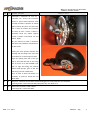
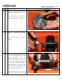
1. 25. Inserire il cuscinetto più grande nell'apposita
sede della flangia. FOTO
Insert the bigger bearing in the predisposed way
of the flange. PICTURE
1. 26. Inserire il cuscinetto più più piccolo nell'apposita
sede della flangia. FOTO
Insert the smaller bearing in the other
predisposed way of the flange. PICTURE
1. 27. Assicurarsi che i cuscinetti siano ben inseriti.
Be sure that the bearings all perfectly put in the flange.
1. 28. Estrarre tutto il contenuto del sacchetto X-033.
From bag X-033, extract all parts.

M
ODULO
1
-
M
ONTAGGIO
R
UOTA
P
OSTERIORE
P
HASE
1
R
EAR
W
HEEL
A
SSEMBLY
2008 – 2.0 – ITA - Eng Modulo 1 / Pag.
7
Mod num Istruzione – Instrucion Foto - Picture
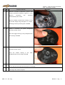
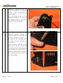
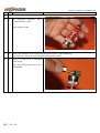
1. 29. Avvitare i 6 grani negli appositi fori filettati
presenti sulle massette, dopo avervi applicato il
frenafiletti. FOTO
NB i grani servono ad aumentare il peso delle
massette nel caso di utilizzo su percorsi lenti.
Screw the 6 grains in the predisposed threaded
holes of the clutch shoes, once applied the
thread lock. PICTURE
Note: the grains are used to make the clutch
shoes heavier, this is useful on slow track and is
suggested for the beginners.
1. 30. Il grano non deve sporgere da nessuno dei due lati delle massette.
The grains have not to jut out from both sides of the clutch shoes.
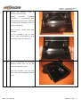
1. 31. Fissare una delle 2 molle ad una delle due
massette avvitando le viti nell’apposita cava,
dopo avervi applicato il frenafiletti. Ripetere
l’operazione con la seconda molla. FOTO
Fix one of the two springs to one of the two
clutch shoes, screwing the screws in the
predisposed way, once applied the thread lock.
Repeat this step with the second spring. PICTURE
1. 32. Applicare l'altra estremità delle 2 molle alla
seconda massetta mediante le altre due viti,
dopo avervi applicato il frenafiletti. FOTO
NB: Le molle non devono sporgere da nessuno dei
due lati delle massette.
Apply the other end of the springs to the second
clutch shoe, using the other two screws, once
applied the thread lock. PICTURE
Note: the springs have not to jut out from both
sides of the clutch shoes.

M
ODULO
1
-
M
ONTAGGIO
R
UOTA
P
OSTERIORE
P
HASE
1
R
EAR
W
HEEL
A
SSEMBLY
2008 – 2.0 – ITA - Eng Modulo 1 / Pag.
8
Mod num Istruzione – Instrucion Foto - Picture
1. 33. Inserire le massette nei perni della flangia
portamassette mantenendo le molle rivolte verso
la flangia. FOTO
Insert both the clutch shoes in the clutch shoes
flange, with the springs close to the flange.
PICTURE
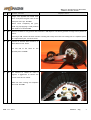
1. 34. Estrarre i 4 satelliti dal sacchetto X-031 e, dopo
avervi inserito i cuscinetti 6x10x2.5, inserirli nei
relativi alberi (FOTO)
NB: se gli ingranaggi non girassero liberamente
allentare le brugole e riserrarle.
From bag X-031, extract 4 satellites and insert
them on the predisposed satellite gear shafts.
(PICTURE)
Note: if the gears don’t spin freely unscrew the
hex screws and tight them again.
1. 35. Infilare la flangia sul perno ruota facendo
ingranare i denti dei satelliti con quelli della
flangia portasatelliti. FOTO
Insert the flange on the wheel pin, engaging the
gears of the satellites with the gears of the
satellite gear flange. PICTURE
36.
1. 37. Verificare che il rotolamento della flangia portasatelliti avvenga senza attrito.
Verify the rolling of the satellite gear flange; it must be free and without friction.

M
ODULO
1
-
M
ONTAGGIO
R
UOTA
P
OSTERIORE
P
HASE
1
R
EAR
W
HEEL
A
SSEMBLY
2008 – 2.0 – ITA - Eng Modulo 1 / Pag.
9
Mod num Istruzione – Instrucion Foto - Picture
1. 38. Estrarre dal sacchetto X-034 il distanziale dello
spessore di 1mm ed inserirlo pel perno ruota fino
al cuscinetto. FOTO
From bag X-034, extract the 1mm spacer and
insert it in the wheel close to the bearing.
PICTURE
1. 39. Estrarre il volano dal sacchetto X-030 ed inserirlo
sul perno ruota. FOTO
From bag X.030, extract the flywheel and insert
it on the wheel pin. PICTURE
1. 40. Verificare che il volano ruoti liberamente.
Verify the free rolling of the flywheel.
1. 41. Estrarre dal sacchetto X-034 il secondo seger.
From bag X-034, extract the second seger.

M
ODULO
1
-
M
ONTAGGIO
R
UOTA
P
OSTERIORE
P
HASE
1
R
EAR
W
HEEL
A
SSEMBLY
2008 – 2.0 – ITA - Eng Modulo 1 / Pag.
10
Mod num Istruzione – Instrucion Foto - Picture
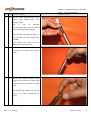
1. 42. Per questa operazione è necessario l'utilizzo degli
occhiali protettivi: inserire il seger nell'apposita
cava del perno ruota adiacente al volano.
Verificare che tutti e tre i nasetti del seger siano
alloggiati all'interno della cava. FOTO
Note: the following step must be done used
safety glasses.
Insert the seger in the predisposed way on the
wheel pin close to the flywheel. Verify that all
the three snug of the seger are placed correctly
in the predisposed way. PICTURE
1. 43. Estrarre dal sacchetto X-034 il distanziale da
2mm ed inserirlo sul perno ruota dal lato volano.
FOTO
From bag X-034, extract the 2mm spacer and
insert it in the wheel pin, flywheel side. PICTURE
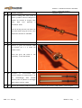
1. 44. Inserire il guscio ruota sinistro (con corona
catena) ed inserirlo sul perno ruota lato volano.
FOTO.
Insert the left wheel shell (the one with the spur
gear) and insert it in the wheel pin, flywheel
side. PICTURE.

M
ODULO
1
-
M
ONTAGGIO
R
UOTA
P
OSTERIORE
P
HASE
1
R
EAR
W
HEEL
A
SSEMBLY
2008 – 2.0 – ITA - Eng Modulo 1 / Pag.
11
Mod num Istruzione – Instrucion Foto - Picture
1. 45. Estrarre dal sacchetto X-034 un secondo
distanziale più piccolo (1mm) ed inserirlo sul
perno ruota. FOTO.
From bag X-034, extract the smaller spacer
(1mm) and insert it in the wheel pin. PICTURE.
1. 46. Estrarre dal sacchetto X-034 una ranella da 4mm
ed inserirla sul perno filettato, estrarre il dado
dal sacchetto X-034 ed avvitarlo a mano sul
perno. FOTO
From bag X-034, extract a 4mm washer and insert
it in the threaded pin, from bag X-034, extract 1
nut and screwing it with hands in the pin.
PICTURE PICTURE.
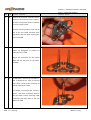
1. 47. Estrarre dal sacchetto X-034 il distanziale più
grande (7.5mm) ed inserirlo sul perno ruota dal
lato portasatelliti. FOTO.
From bag X-034, extract the bigger spacer
(7.5mm) and insert it in the wheel pin, satellite
gear shaft side. PICTURE.

M
ODULO
1
-
M
ONTAGGIO
R
UOTA
P
OSTERIORE
P
HASE
1
R
EAR
W
HEEL
A
SSEMBLY
2008 – 2.0 – ITA - Eng Modulo 1 / Pag.
12
Mod num Istruzione – Instrucion Foto - Picture
1. 48. Inserire il guscio ruota destro sul perno ruota
facendo combaciare i fori di fissaggio delle viti.
FOTO.
Insert the right wheel shell in the wheel pin,
matching the fixing screws holes. PICTURE.
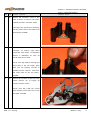
1. 49. Estrarre dal sacchetto X-034 il distanziale più
piccolo (1mm) ed inserirlo sul perno ruota.
Estrarre dal sacchetto X-034 la seconda ranella
da 4mm ed inserirla sul perno filettato. Estrarre
il secondo dado dal sacchetto X-034 ed avvitarlo
a mano sul perno. FOTO
From bag X-034, extract the smaller spacer
(1mm) and insert it in the wheel pin.
From bag X-034, extract the second washer, and
insert it in the threaded pin.From bag X-034,
extract the second nut and screw it, manually, in
the pin. PICTURE
1. 50. Estrarre le 6 viti dal sacchetto X-031 ed avvitarle
nelle apposite sedi senza forzare.FOTO
From bag X-031, extract the 6 cross screws, and
screw them in the predisposed ways, avoiding to
force. PICTURE
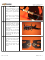
1. 51. Prendere il copertone posteriore dalla scatola ed estrarre la spugna adesiva poggiata al suo interno.

M
ODULO
1
-
M
ONTAGGIO
R
UOTA
P
OSTERIORE
P
HASE
1
R
EAR
W
HEEL
A
SSEMBLY
2008 – 2.0 – ITA - Eng Modulo 1 / Pag.
13
Mod num Istruzione – Instrucion Foto - Picture
From the box, take the rear tire (the one with bigger gear cutting and smaller diameter) and the sticky
sponge (placed in the interior of tire).
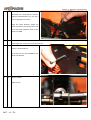
1. 52. Sollevare un piccola porzione della protezione
adesiva ed iniziare ad incollare la spugna come
da foto. FOTO
Lift a small portion of the sticky sponger and
begin to adhere it on the wheel as described in
the PICTURE.
1. 53. Proseguire ad incollare la spugna sollevando
gradualmente la protezione adesiva fino a
completare il giro.
Go ahead with this action gradually removing the
protection from the sticky sponge, completing an
entire round.
1. 54. Calzare il copertone sulla ruota. FOTO.
Fit the tire on the wheel. PICTURE.

M
ODULO
1
-
M
ONTAGGIO
R
UOTA
P
OSTERIORE
P
HASE
1
R
EAR
W
HEEL
A
SSEMBLY
2008 – 2.0 – ITA - Eng Modulo 1 / Pag.
14
Mod num Istruzione – Instrucion Foto - Picture
55. ASSEMBLAGGIO VOLANO ELETTRICO ELECTRIC FLY WHEEL ASSEMBLY
1. 56. Prendere l’assemblato dell’albero ruota con il
gruppo motore-regolatore
Take the rear wheel shaft assembled with the
motor-ESC assembly.
1. 57. Inserire il seeger nell’apposita cava.
Insert the C-clip into it’s groove

M
ODULO
1
-
M
ONTAGGIO
R
UOTA
P
OSTERIORE
P
HASE
1
R
EAR
W
HEEL
A
SSEMBLY
2008 – 2.0 – ITA - Eng Modulo 1 / Pag.
15
Mod num Istruzione – Instrucion Foto - Picture
1. 58. Inserire il gruppo volano.
Insert the flywheel.
1. 59. Se necessario inserire un distanziale da 2 mm
contro il volano
If necessary insert the 2mm spacer against the
flywheel
1. 60. Ferma il gruppo con il seeger.
Secure in place the flywheel with the C-clip.
1. 61. Estrarre il guscio ruota più spesso con i perni dal
sacchetto x-002 e la flangia porta corona dal
sacchetto X-303 ed avvitarla al semi guscio.
Successivamente estrarre dal sacchetto X-305 la
La pagina sta caricando ...
La pagina sta caricando ...
La pagina sta caricando ...
La pagina sta caricando ...
La pagina sta caricando ...
La pagina sta caricando ...
La pagina sta caricando ...
La pagina sta caricando ...
La pagina sta caricando ...
La pagina sta caricando ...
La pagina sta caricando ...
La pagina sta caricando ...
La pagina sta caricando ...
La pagina sta caricando ...
La pagina sta caricando ...
La pagina sta caricando ...
La pagina sta caricando ...
La pagina sta caricando ...
La pagina sta caricando ...
La pagina sta caricando ...
La pagina sta caricando ...
La pagina sta caricando ...
La pagina sta caricando ...
La pagina sta caricando ...
La pagina sta caricando ...
La pagina sta caricando ...
La pagina sta caricando ...
La pagina sta caricando ...
La pagina sta caricando ...
La pagina sta caricando ...
La pagina sta caricando ...
La pagina sta caricando ...
La pagina sta caricando ...
La pagina sta caricando ...
La pagina sta caricando ...
La pagina sta caricando ...
La pagina sta caricando ...
La pagina sta caricando ...
La pagina sta caricando ...
La pagina sta caricando ...
La pagina sta caricando ...
La pagina sta caricando ...
La pagina sta caricando ...
La pagina sta caricando ...
La pagina sta caricando ...
La pagina sta caricando ...
La pagina sta caricando ...
La pagina sta caricando ...
La pagina sta caricando ...
La pagina sta caricando ...
La pagina sta caricando ...
La pagina sta caricando ...
La pagina sta caricando ...
La pagina sta caricando ...
La pagina sta caricando ...
La pagina sta caricando ...
La pagina sta caricando ...
La pagina sta caricando ...
La pagina sta caricando ...
La pagina sta caricando ...
La pagina sta caricando ...
La pagina sta caricando ...
La pagina sta caricando ...
La pagina sta caricando ...
La pagina sta caricando ...
La pagina sta caricando ...
La pagina sta caricando ...
La pagina sta caricando ...
-
 1
1
-
 2
2
-
 3
3
-
 4
4
-
 5
5
-
 6
6
-
 7
7
-
 8
8
-
 9
9
-
 10
10
-
 11
11
-
 12
12
-
 13
13
-
 14
14
-
 15
15
-
 16
16
-
 17
17
-
 18
18
-
 19
19
-
 20
20
-
 21
21
-
 22
22
-
 23
23
-
 24
24
-
 25
25
-
 26
26
-
 27
27
-
 28
28
-
 29
29
-
 30
30
-
 31
31
-
 32
32
-
 33
33
-
 34
34
-
 35
35
-
 36
36
-
 37
37
-
 38
38
-
 39
39
-
 40
40
-
 41
41
-
 42
42
-
 43
43
-
 44
44
-
 45
45
-
 46
46
-
 47
47
-
 48
48
-
 49
49
-
 50
50
-
 51
51
-
 52
52
-
 53
53
-
 54
54
-
 55
55
-
 56
56
-
 57
57
-
 58
58
-
 59
59
-
 60
60
-
 61
61
-
 62
62
-
 63
63
-
 64
64
-
 65
65
-
 66
66
-
 67
67
-
 68
68
-
 69
69
-
 70
70
-
 71
71
-
 72
72
-
 73
73
-
 74
74
-
 75
75
-
 76
76
-
 77
77
-
 78
78
-
 79
79
-
 80
80
-
 81
81
-
 82
82
-
 83
83
-
 84
84
-
 85
85
-
 86
86
-
 87
87
-
 88
88
-
 89
89
-
 90
90
-
 91
91
-
 92
92
-
 93
93


ARX Racing ARM-540 PK Manuale utente
- Categoria
- Giocattoli telecomandati
- Tipo
- Manuale utente
in altre lingue
- English: ARX Racing ARM-540 PK User manual
Altri documenti
-
PROEL PB90 Series Professional Height Adjustable Bench for Piano Manuale utente
-
Ducati monster S4 fogarty 2002 Workshop Manual
-
Falmec Iseo Corner Manuale utente
-
-
-
Husqvarna TC Manuale del proprietario
-
Beta REV 50 Manuale utente
-
-
Ferrari 2003 Challenge Stradale Manuale del proprietario
-